Solution Manual for Introduction to Mechatronic Design Do Not Circulate
Chapter 9 Basic Circuit Analysis and Passive Components
9.1) If, for a particular two-terminal device the voltage and current entering one terminal is 7.5 V and 1 A and
the voltage and current leaving the other terminal is 5 V and 1 A, how much power is being dissipated in
the device?
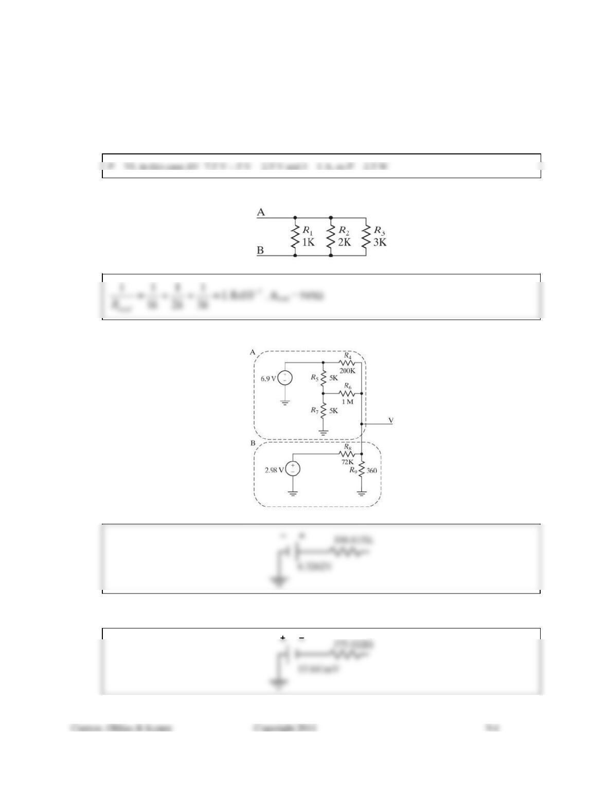
9.2) What is the resistance seen across terminals A and B in Figure 9.61?
Figure 9.61 Circuit for Problem 9.2.
9.3) Determine the Thevenin equivalent circuit for the subcircuit block labeled A in Figure 9.62.
Figure 9.62 Circuit for Problems 9.3-9.6.
9.4) Determine the Thevenin equivalent circuit for the subcircuit block labeled B in Figure 9.62.
Solution Manual for Introduction to Mechatronic Design Do Not Circulate
9.5) What is the voltage at the point labeled V in Figure 9.62?
Combining the Thevenin equivalents of Problems
9.3 and 9.4 gives us a circuit like that to the left.
9.6) If the voltage at point V in Figure 9.62 were measured with a voltmeter with a 100 k internal resistance,
what voltage would be measured?
The Thevenin equivalent resistance would simply be 166.615 k || 375.022 or 374 . This would form a
voltage divider with the 100 k of the meter and we would read:
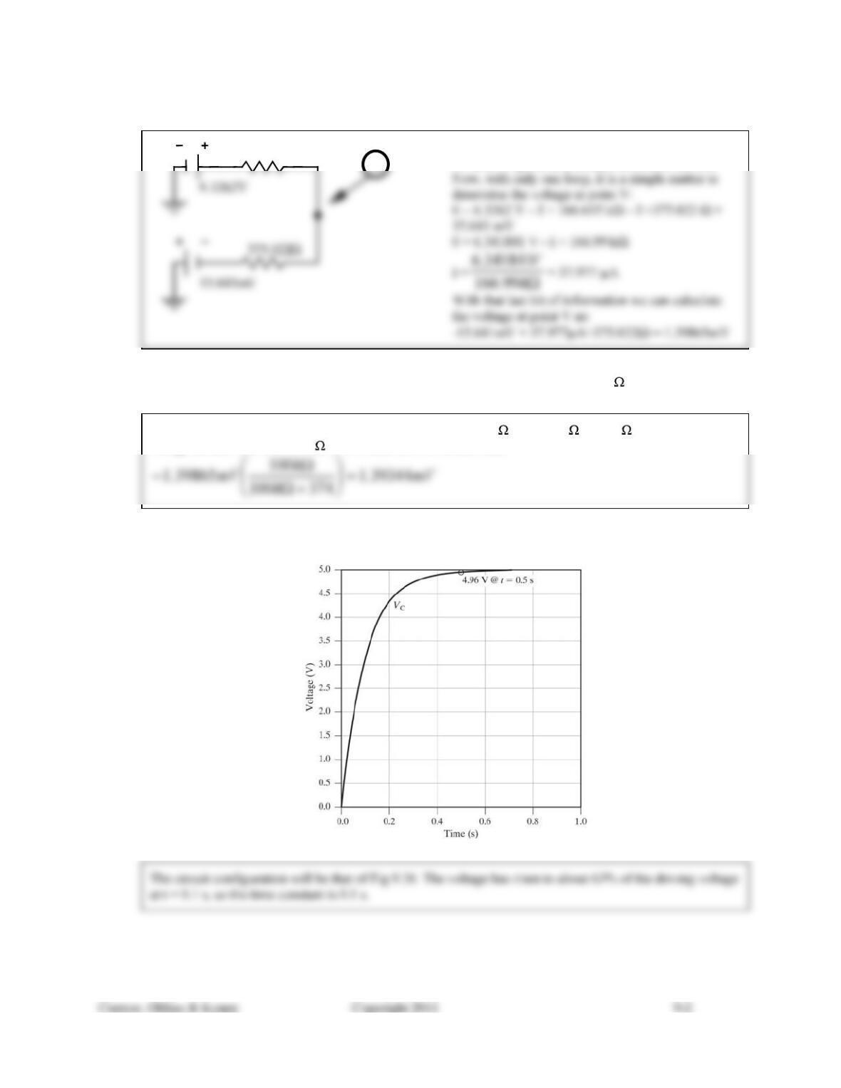
9.7) The graph in Figure 9.63 represents the output of an RC circuit excited by a 0-5 V rising edge. Draw the
RC circuit configuration. Based on the data shown, what is the time constant?
Figure 9.63 Waveform for Problem 9.7.
166.615KV
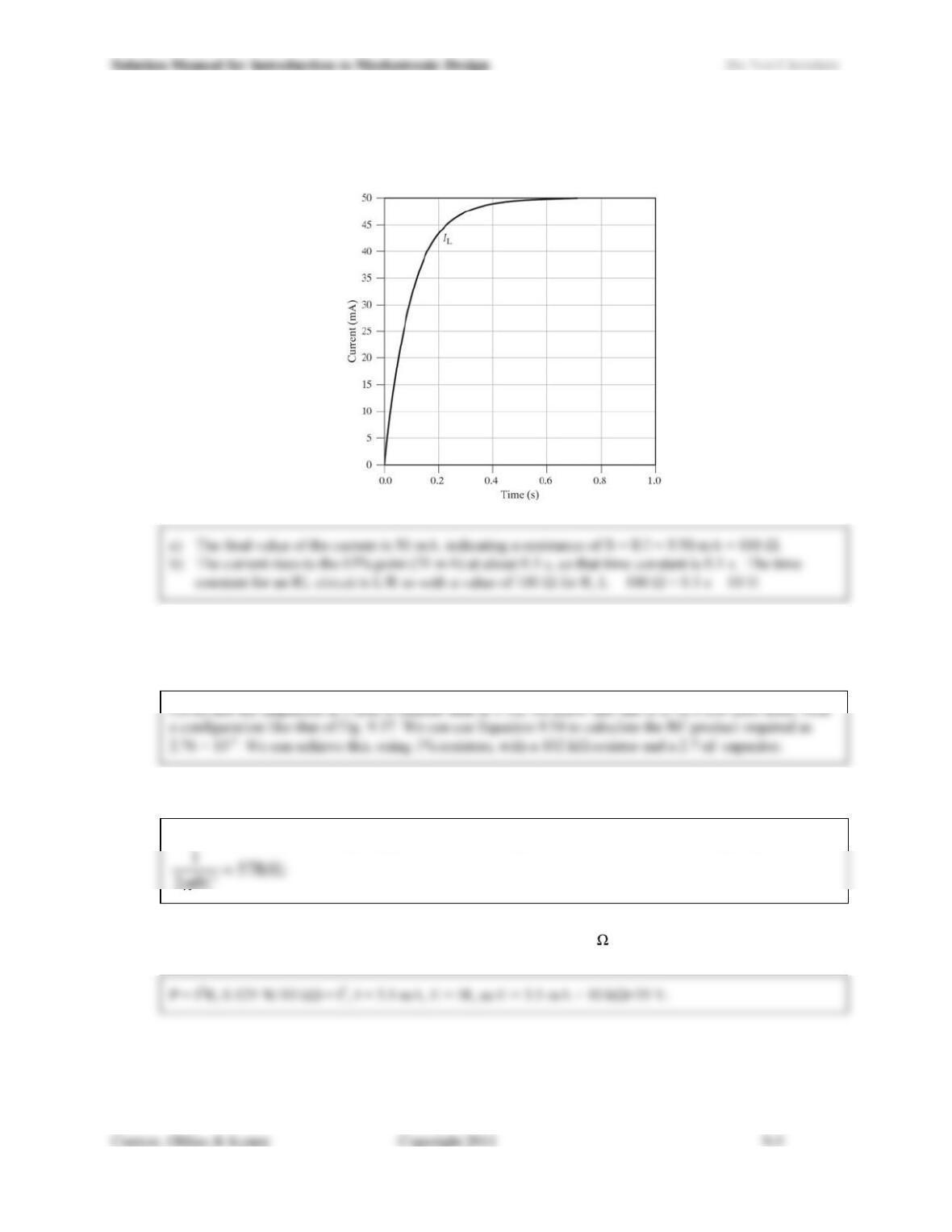
9.8) Figure 9.64 shows the current waveform for a series RL circuit excited by a 0-5 V rising edge.
a) Estimate the total resistance seen by the exciting voltage source.
b) Estimate the inductance in the circuit.
Figure 9.64 Waveform for Problem 9.8.
9.9) Design a circuit that takes a sinusoidal input of varying frequency at 1 V amplitude and produces an output
amplitude of approximately 1 V when the frequency is 1 Hz and approximately 0.5 V when the frequency
is 1,000 Hz. Choose real component values to get as close as possible to the specified amplitudes.
9.10) For the circuit that you designed in Problem 9.9, at what frequency is the output approximately 0.707 V?
Since 0.707 is the corner frequency point, we can use Eq. 9.55 to calculate the corner frequency:
9.11) What is the minimum voltage would you need to apply across a 10 k 1/8 W resistor in order to cause its
power rating to be exceeded?
9.12) If a resistor with a temperature coefficient of 1,000 ppm that measures 997 at 25°C is cooled to -40°C (a
cold night in Minnesota), what range of resistances would you expect to see? How about if it were heated
to 65°C (inside a car on a sunny summer day in Arizona)?
9.13) Which capacitor would you expect to be physically larger: a 0.1 F ceramic disk or a 0.1 F monolithic
ceramic capacitor?
9.14) Which capacitor would you expect to be physically larger: a 10 F electrolytic or a 10 F tantalum
capacitor?
9.15) If a monolithic ceramic capacitor were labeled 103X5F, what would you expect its capacitance value to
be?
9.16) You have been presented with two monolithic ceramic capacitors. One is labeled 104C0G, the other
104Z5U. How are these capacitors alike? How are they different?
9.17) If you were designing an RC low-pass filter to operate with a corner frequency of 10 kHz for a signal of a
few volts amplitude at less than 0.1 mA, what types of resistors and capacitors (i.e., which values and
technologies) would be good choices?
9.18) Design a circuit that takes a sinusoidal input of varying frequency at 1 V amplitude and produces an output
amplitude of approximately 1 V when the frequency is 1,000 Hz and approximately 0.5 V when the
frequency is 1 Hz. Choose real component values to get as close as possible to the specified amplitudes.
9.19) Some monolithic ceramic capacitor materials exhibit a voltage dependency. What happens as the applied
voltage is increased?
9.20) List two examples each of polar and nonpolar capacitor types.