
Solution Manual for Introduction to Mechatronic Design Do Not Circulate
Chapter 24 Solenoids
24.1) Describe the general characteristics of applications in which solenoids may be a good choice.
24.2) If solenoids prove to be a poor choice for meeting the requirements of a given application, name at least
three alternative means of creating linear motion.
There are many answers to this question (far more than three), including:
Motor (e.g., brushed DC, brushless DC, stepper, etc.) with rack and pinion gearing
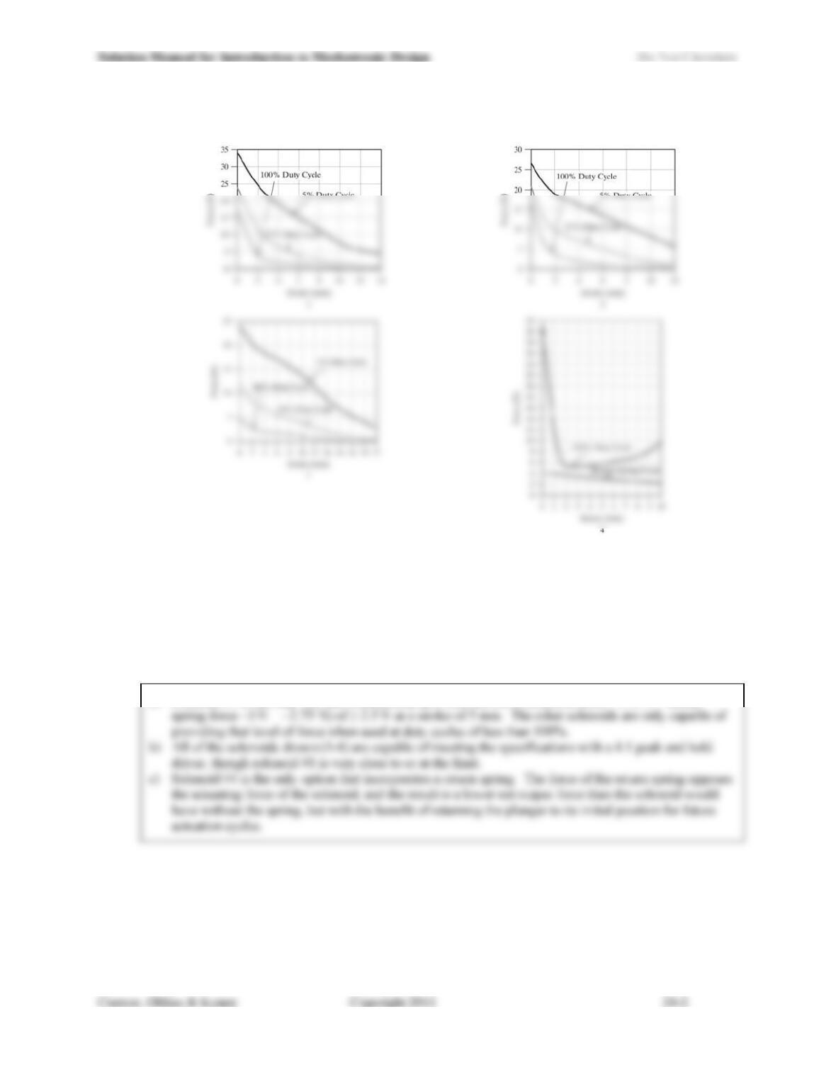
24.3) Given the performance characteristics for four solenoids shown in Figure 24.13, answer the following
questions:
Figure 24.13: Data for Problem 24.3.
a) Which solenoid(s) would be suitable for a continuous duty application that needed to provide more
than 2.5 N of force at a displacement of 5 mm?
b) Which solenoid(s) would be suitable for the same application if a 4:1 peak and hold driver (i.e., the
initial phase of actuating the solenoid is driven with four times the voltage corresponding to a
continuous duty cycle) were used to drive the solenoid?
c) The construction of solenoid #4 differs from that of the others shown. How is it different? What
impact does the difference have on its force vs. stroke characteristics?
a) Solenoid #4 is the only one that continuously provides net force (solenoid force ~5.75 N return
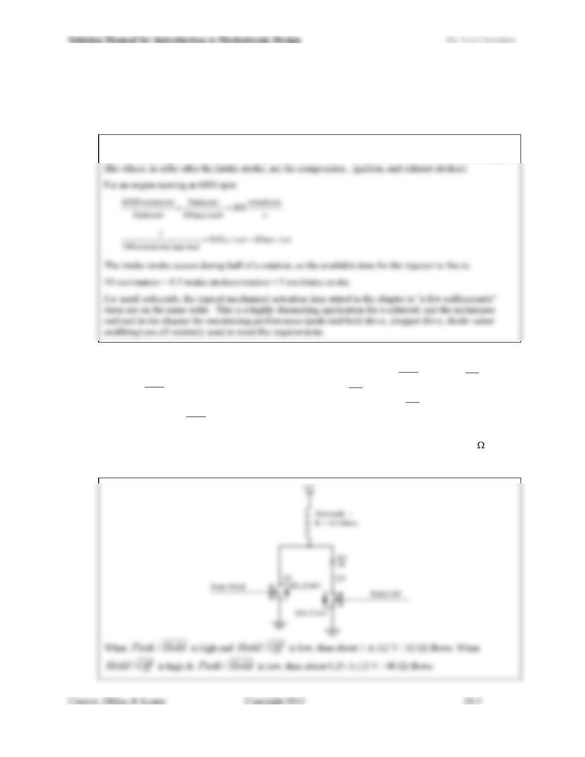
24.4) The performance requirements for an automotive fuel injector are stringent. For example, calculate the
total time available for a fuel injector to introduce fuel into an automotive cylinder when a four-stroke
engine is turning at 6,000 rpm. How does this compare to the mechanical actuation times of typical
solenoids?
For a four-stroke engine, the only beneficial time to allow fuel to flow through the injector and into the
cylinder is during the intake stroke, which is the first of the 4 strokes, or 180° of rotation, of the engine
24.5) Design a peak and hold driver that will take two separate 0-5 V digital inputs and control the current
through a solenoid to a 4:1 peak:hold ratio. The two inputs are called HoldPeak / and OffHold /. When
the HoldPeak / input has is in the logical high state, the OffHold / input will be in a logical low state, and
the current through the solenoid should be at the peak value. When the OffHold / input is in the logical
high state, the HoldPeak / input will be in the logical low state and the current should be at the hold value.
When both inputs are in the logical low state, the solenoid should be off (no current flowing). The two
inputs will never be in the logical high state at the same time. The solenoid has a resistance of 12 and
will be operated from a 12 V power supply. Choose standard 5% resistor values, but do not account for the
5% variation in your answer when assessing the current ratios.
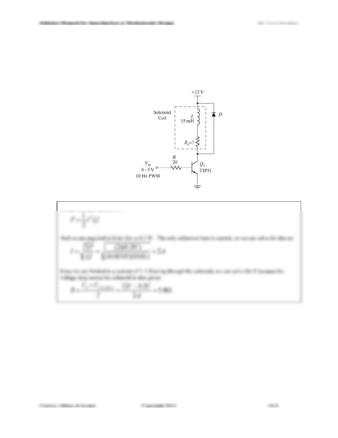
24.6) The circuit shown in Figure 24.14 uses a standard diode (whose maximum average power dissipation
specification is 0.3 W) as a snubber. If the solenoid is driven with PWM at a frequency of 10 Hz, what is
the minimum coil resistance Rc that the solenoid may have without violating the diodes power dissipation
specification? You may assume that VCE(SAT), the voltage drop across the TIP31 transistors collector and
emitter, is 0.5 V when the transistor is on and saturated. You may also assume that the diode D has a
forward voltage drop of 0.6 V when forward biased.
Figure 24.14: Circuit for Problem 24.6.
The governing expression is:
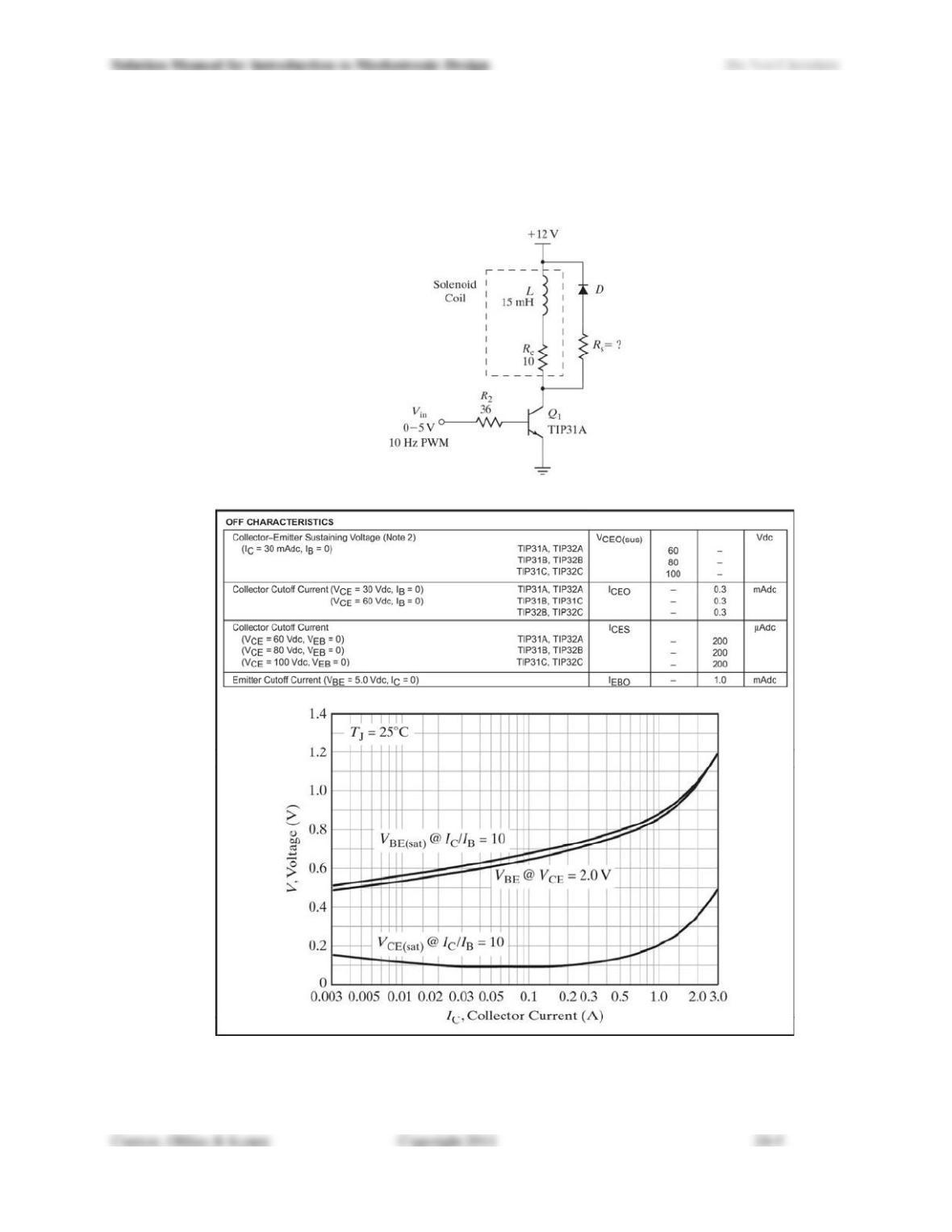
24.7) For the circuit shown in Figure 24.15, specify the resistor Rs in the diode-resistor snubber circuit that
results in the fastest possible decay of current flowing in the solenoid and does not violate specifications
for any circuit component. Use the specifications provided for the TIP31 in Figure 24.16, and select a
resistor with standard 5% tolerance. You may assume that the diode D has a forward voltage drop of 0.6 V
when forward biased.
Figure 24.15: Circuit for Problem 24.7.
Figure 24.16: Data for Problem 24.7. (Used with permission from SCI LLC, DBA ON Semiconductor.)
Solution Manual for Introduction to Mechatronic Design Do Not Circulate
Solution for Problem 24.7:
NOTE: The problem statement incorrectly omits the A in TIP31A for Q1. This was omitted in error,
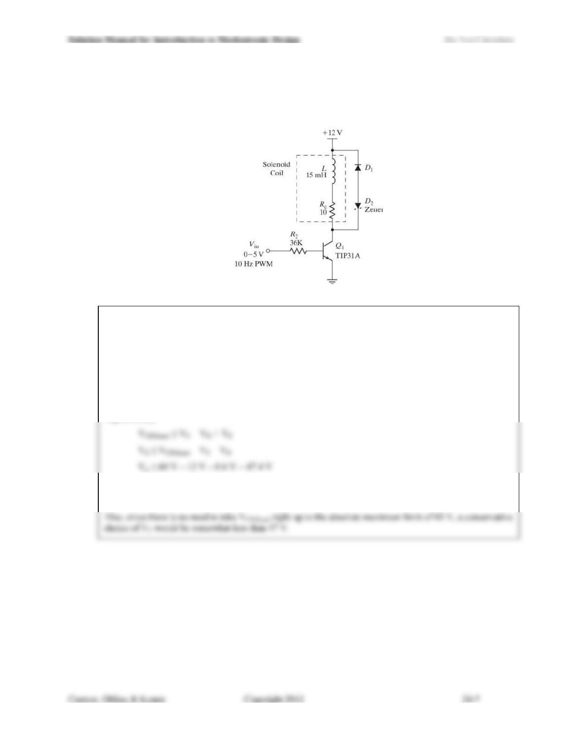
24.8) Specify the Zener voltage for the Zener diode (D2) shown in the circuit of Figure 24.17. You may use the
specifications for the TIP31 provided in Problem 24.7. You may assume that the diode D1 has a forward
voltage drop of 0.6 V when forward biased. Include the data sheet for the Zener diode you select in your
answer.
Figure 24.17: Circuit for Problem 24.8.
NOTE: The problem statement incorrectly omits the A in TIP31A for Q1. This was omitted in error,
and the circuit schematic in Figure 24.17 is as intended. Since specifications for a TIP31 are not included
in Figure 24.16, this omission is not likely to cause too much confusion.
The goal of this problem is the same as Problem 24.7: allow the voltage at the collector of Q1 (VC) to
come as close as possible to the maximum allowable value (VCEO(sus) = 60 V), without exceeding it. This
can be achieved by specifying a Zener diode with a reverse breakdown voltage, VZ, that, in combination
with the power supply and the forward diode drop across D1, is close to, but not greater than, VCEO(sus) = 60
V.
Algebraically:
Any value up to VZ = 47V is an acceptable response.
A better answer takes into consideration the tolerance of the part (1%? 2.5% 5%?).
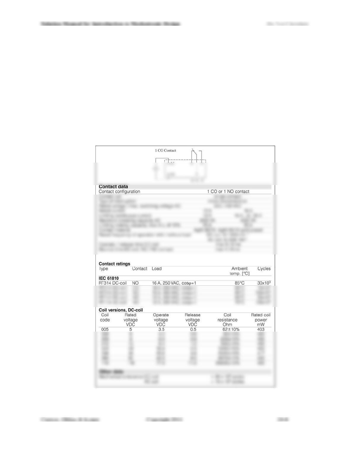
24.9) The electrical relay shown in Figure 24.18 (the RT1 from Tyco Electronics) is capable of switching up to
250 VAC at 16 A with a 0 to 5 V input signal. Using the specifications provided for the RT114005 (5V
DC coil), answer the following questions:
a) When controlling the coil with a 5 V drive signal, how much current will flow? What is the threshold
voltage at which the contacts will close? What is the threshold voltage at which the contacts will
open?
b) How many switching cycles are the electrical contacts rated for? How many actuation cycles are the
mechanical elements rated for? Which is most likely to fail first?
c) What is the highest voltage and current you can control with this relay?
d) How quickly can the contacts switch on or off? Is it reasonable to use this relay to implement PWM
control? Why or why not?
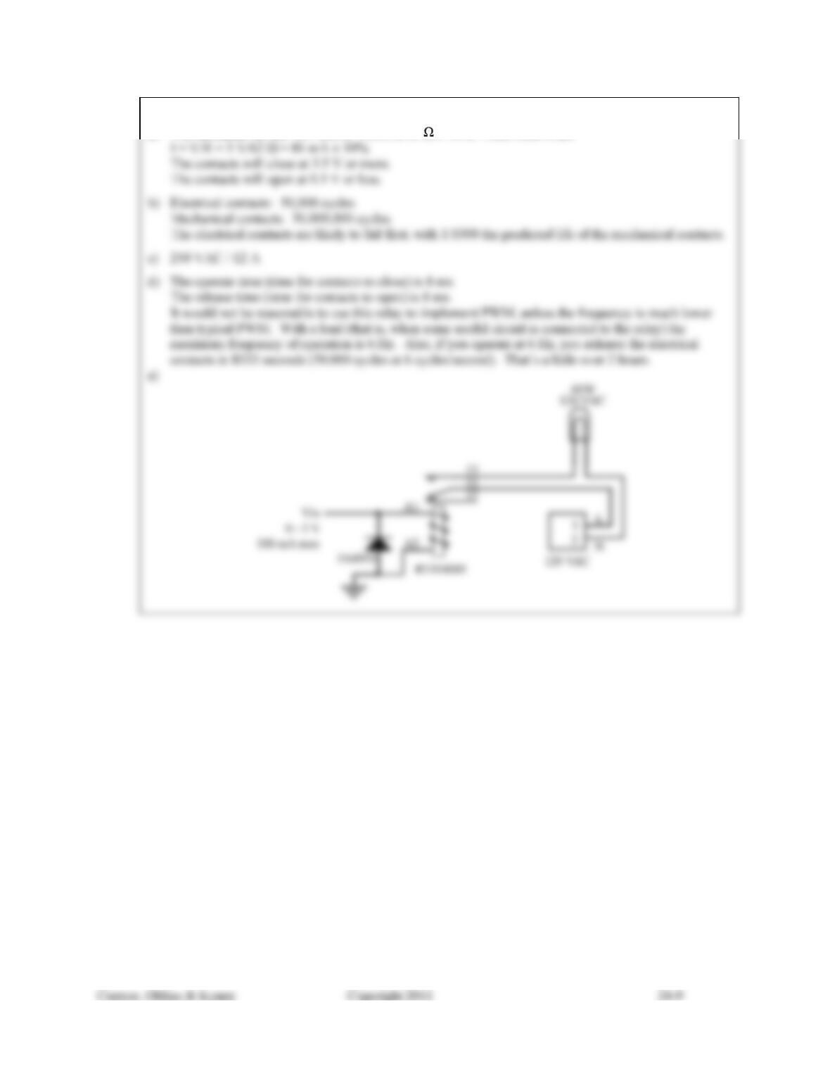
e) You are to use this relay to build a motion controlled porch light. Design a circuit which controls
power to a standard 120 VAC / 60 W light bulb with an input signal that is 0 V when the light bulb is
off and 5 V at up to 100 mA when the light bulb is to be on.
Figure 24.18: Relay and data for Problem 24.9. (Courtesy of Tyco Electronics Corp.)
Solution Manual for Introduction to Mechatronic Design Do Not Circulate
Solution for Problem 24.9:
a) The resistance for the -005 coil (5 VDC) is 62 ± 10%. From Ohms law
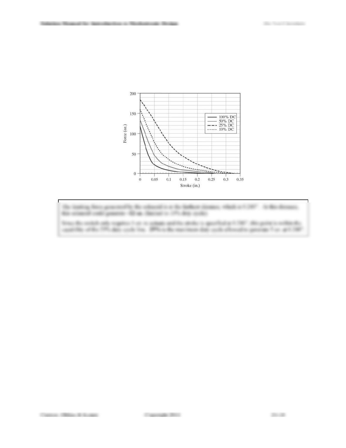
24.10) You are building a test fixture for a piece of electronic equipment, and you need to characterize the life of a
momentary switch located on the devices front panel. You decide to use a solenoid with the
characteristics shown in Figure 24.19 to depress the switch repeatedly and count the number of cycles until
failure. If you position the solenoid plunger 0.220 in. away from the switch and the switch deflects 0.020
in. when pressed, what is the maximum force you can generate with the solenoid in the fixture? If the
switch requires 5 oz., what is the corresponding maximum duty cycle you can use with this solenoid?
Figure 24.19: Data for Problem 24.10.
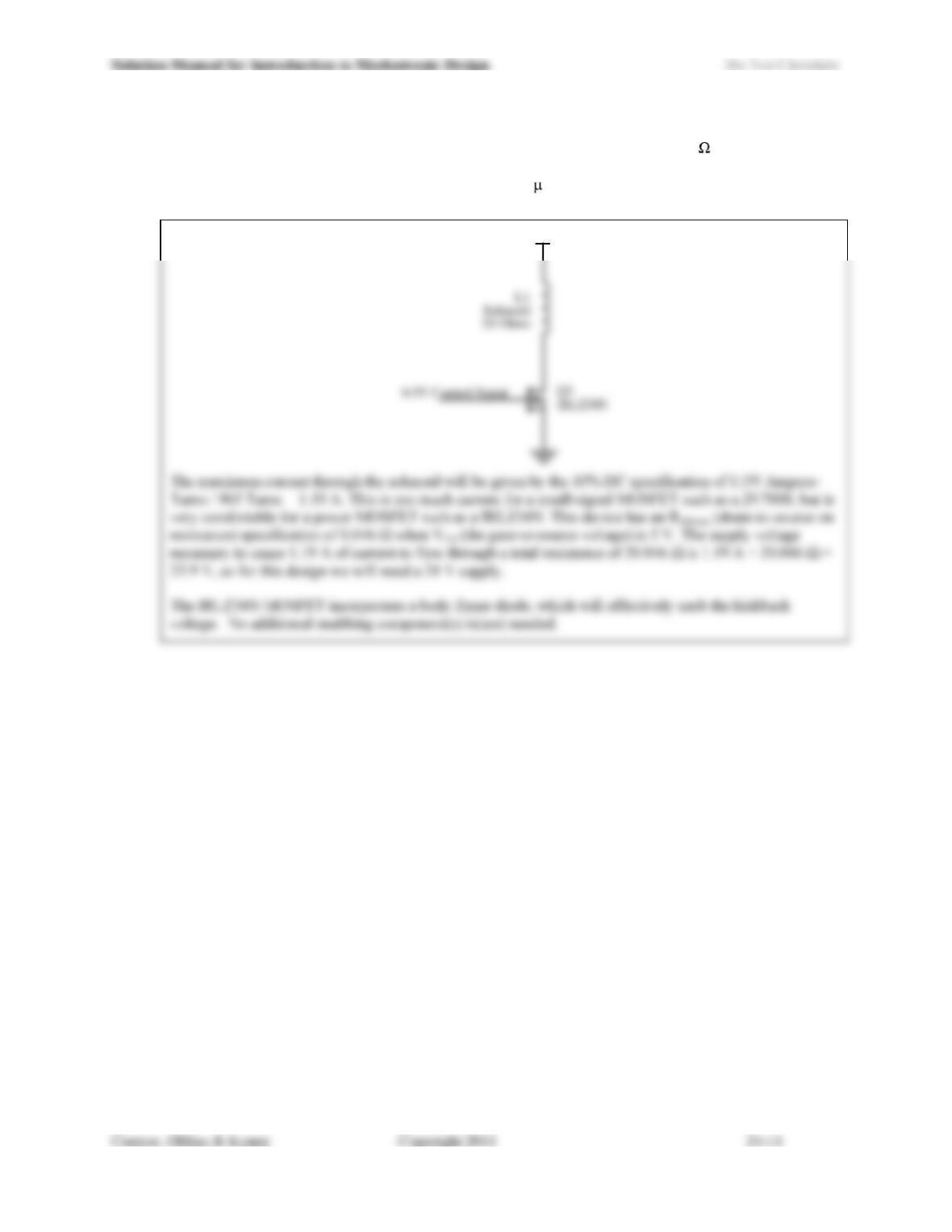
24.11) If the solenoid from Problem 24.10 has 965 turn windings and a DC resistance of 20 , design a drive
circuit to control the solenoid at the maximum permissible current for 10% duty cycle. The control signal
will be a 0-5 V output from a microcontroller. (IOH = -100 A). Specify the components and necessary
power supply voltage chosen from the set of 5, 12, 15 and 24 V.
+24V