
Solution Manual for Introduction to Mechatronic Design Do Not Circulate
Chapter 23 Permanent Magnet Brushed DC Motor Applications
23.1) Why is it necessary to include a snubber circuit when switching inductive circuit elements (e.g., brushed
DC motors)?
23.2) Name at least two benefits of using higher PWM frequencies.
Solution Manual for Introduction to Mechatronic Design Do Not Circulate
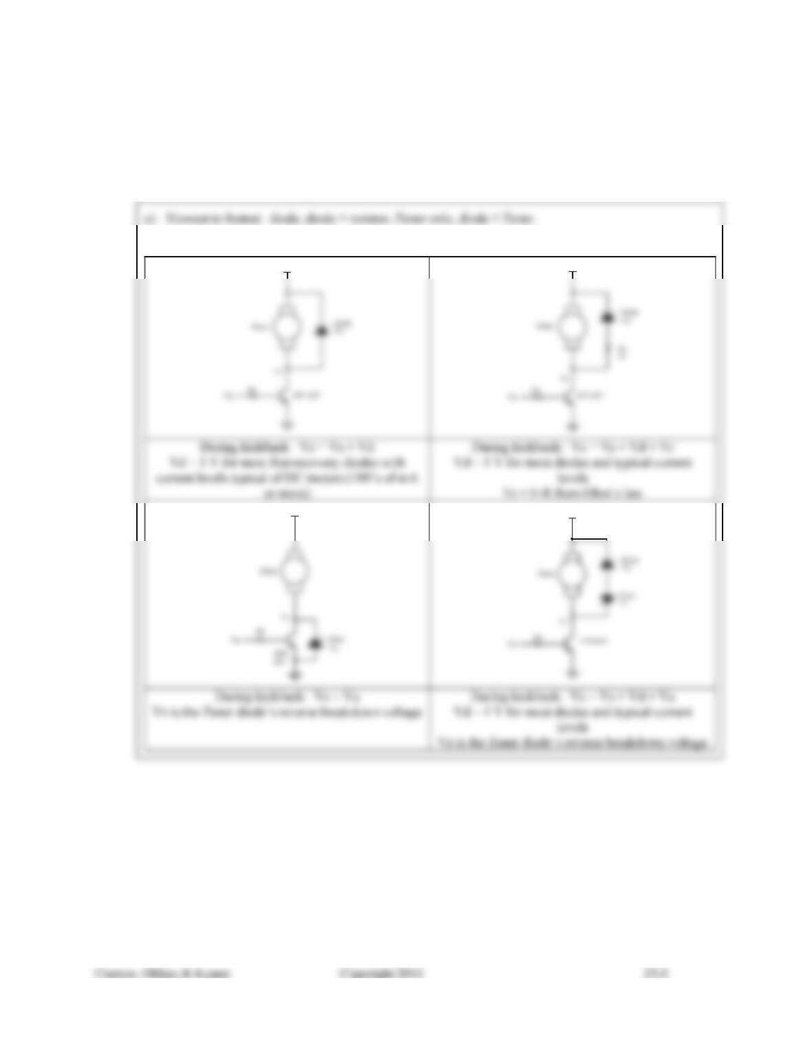
23.3) For each of the snubbing methods described in this chapter:
a) Rank them in order of slowest current decay time to fastest.
b) Draw a schematic showing how each is connected, label the peak voltage drops across each of the
components that comprise the snubber circuit, and write the expression for the peak voltage at the
connection to the switching element.
b)
Vs
Vs
Vs
Vs
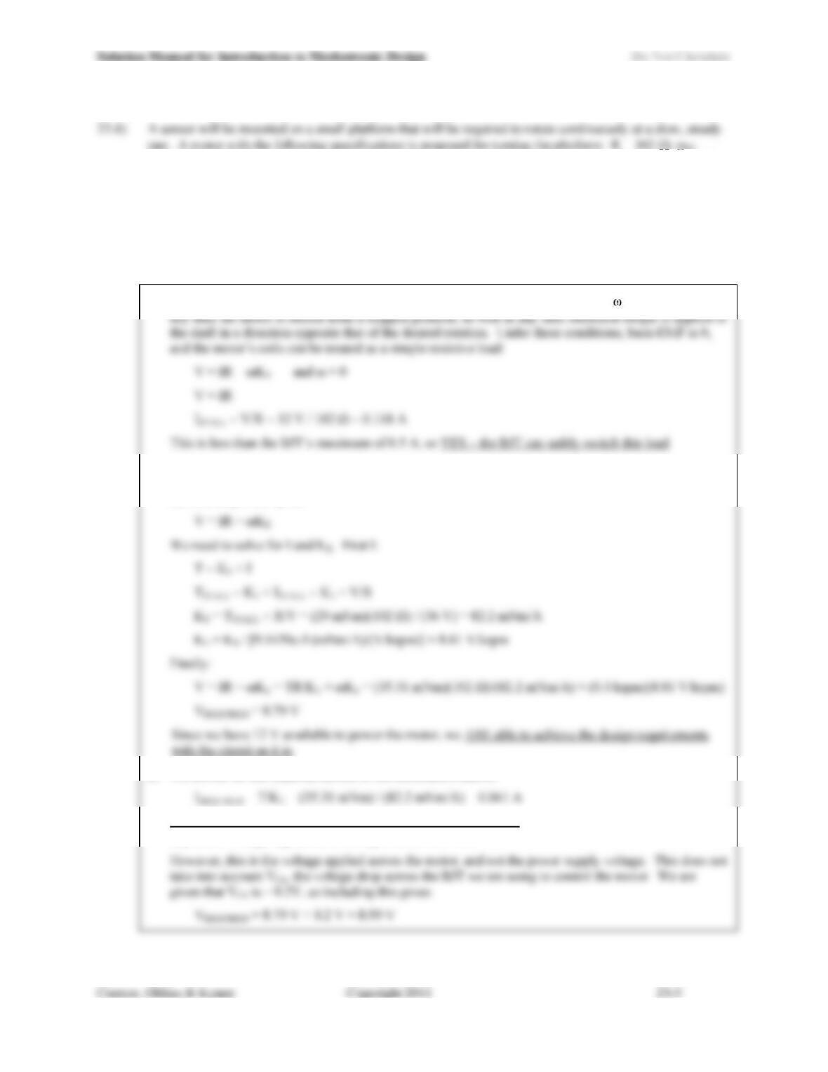
427.3 rad/s at 36 V, TSTALL = 29 mNm at 36 V. The application calls for the motor to deliver 5 oz.·in. of
torque at 300 rpm. The system is to be powered by a 12 V supply and switched by a BJT rated to handle a
maximum of 500 mA continuously with a collector-emitter voltage drop of VCE = 0.2 V.
a) Can the BJT safely switch the required current?
b) Is it possible to meet the design requirements for torque and speed with the given motor and power
supply? Justify your answer and show all calculations performed to reach your conclusion.
c) What is the average current required when running at the design point?
d) What applied voltage is required when running at the design point?
a) The highest current that will occur at any point in operation is stall current (when = 0). This happens
b) Solve the voltage equation to see if the required V is lower than the available voltage from the power
supply. If so, we can use a technique such as PWM to adjust the average voltage to achieve the
desired torque and speed.
c) We solved for the required current in the calculations above:
d) The required voltage (see our solution to part B above) is 8.79 V. We can create this with an
adjustable voltage regulator, or through the use of PWM.
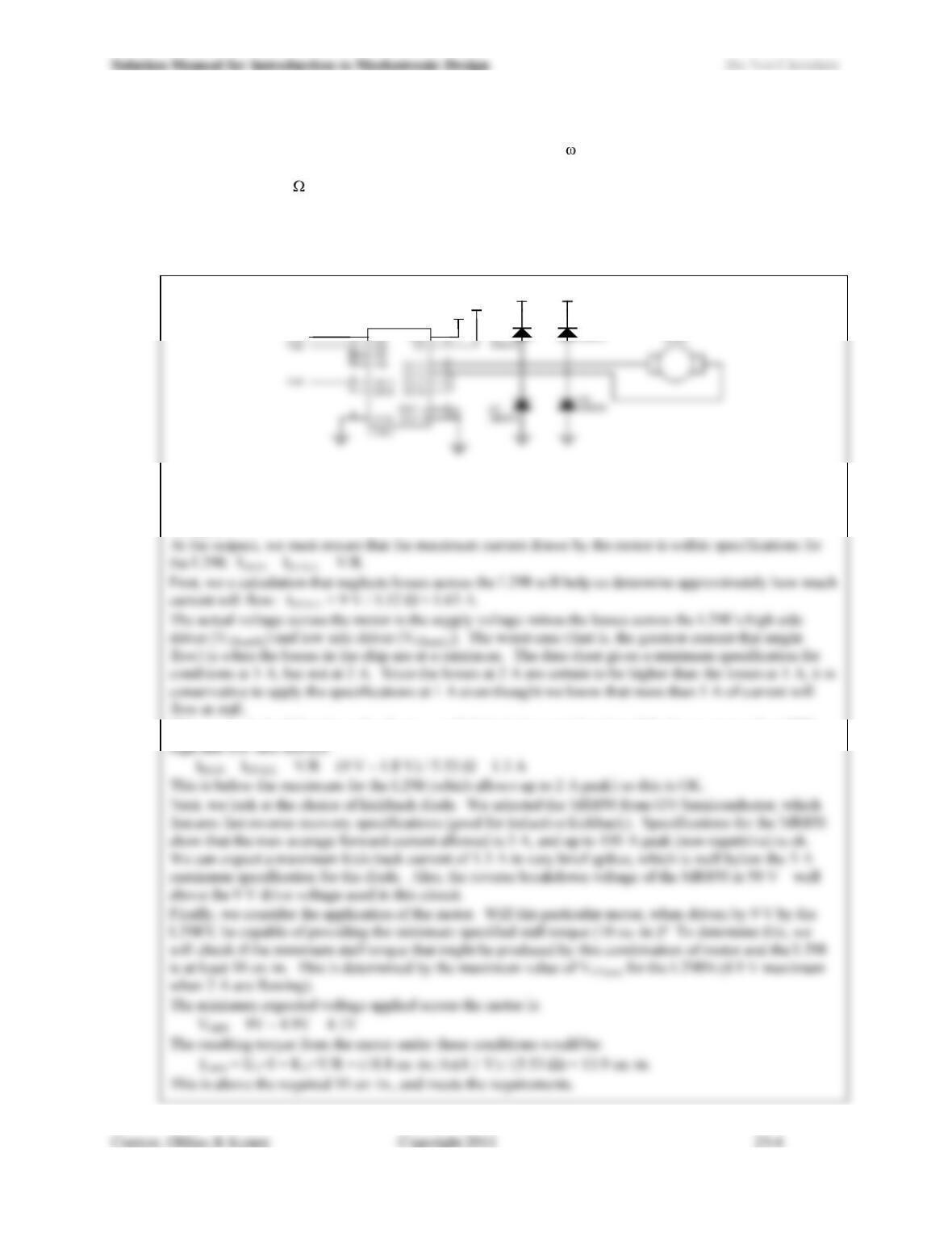
23.5) A Pittman 14203-48 DC motor is to be used in an application where it is required to produce torque of at
least 10 oz.·in. when stalled. The motor has a no-load speed of NL = 3,330 rpm (at 40 V), stall torque TS
= 161 oz.·in. (also at 40 V), torque constant KT = 18.8 oz.·in./A, speed constant KE = 13.9 V/krpm, and
resistance R = 5.53 . Design a circuit to drive the motor using an ST L298N H-bridge with two separate
power supplies: +9 V for driving the motor and +5 V for powering the logic. Incorporate kickback diode
protection. The design should take in logic-level signals for enabling the motor (turning it on and off) and
changing the direction of the motors rotation. Show how all specifications of the motor, the kickback
diodes and the L298N are satisfied.
5
U1
D1 MR850
D2
+9V +9V
Vin1
+9V
+5V
For the L298N, the logic-level inputs satisfy the requirements, and the power supplies are also within
specifications at 5 V for the logic and 9 V for the motor (which must be at least 2.5 V above the logic input
voltage).
This results in the following value for IMAX, which includes consideration of the losses across the L298s
23.6) A motor with a stall current of 0.9 A and coil inductance of 12 mH is driven with PWM frequency of 500
Hz. The kickback protection for the drive circuit consists of a standard diode (a 1N4935) in combination
with a 24 V, 5 W Zener diode (a 1N5359B). What is the peak power dissipated by the standard diode? By
the Zener? Does this circuit operate within the specifications of these diodes?
For the 1N4935: Since no power dissipation specification is provided, we must calculate it from other
specifications.
Eq. 23.8 gives us the approximate power dissipation that results in the circuit:
This is OK for both parts:
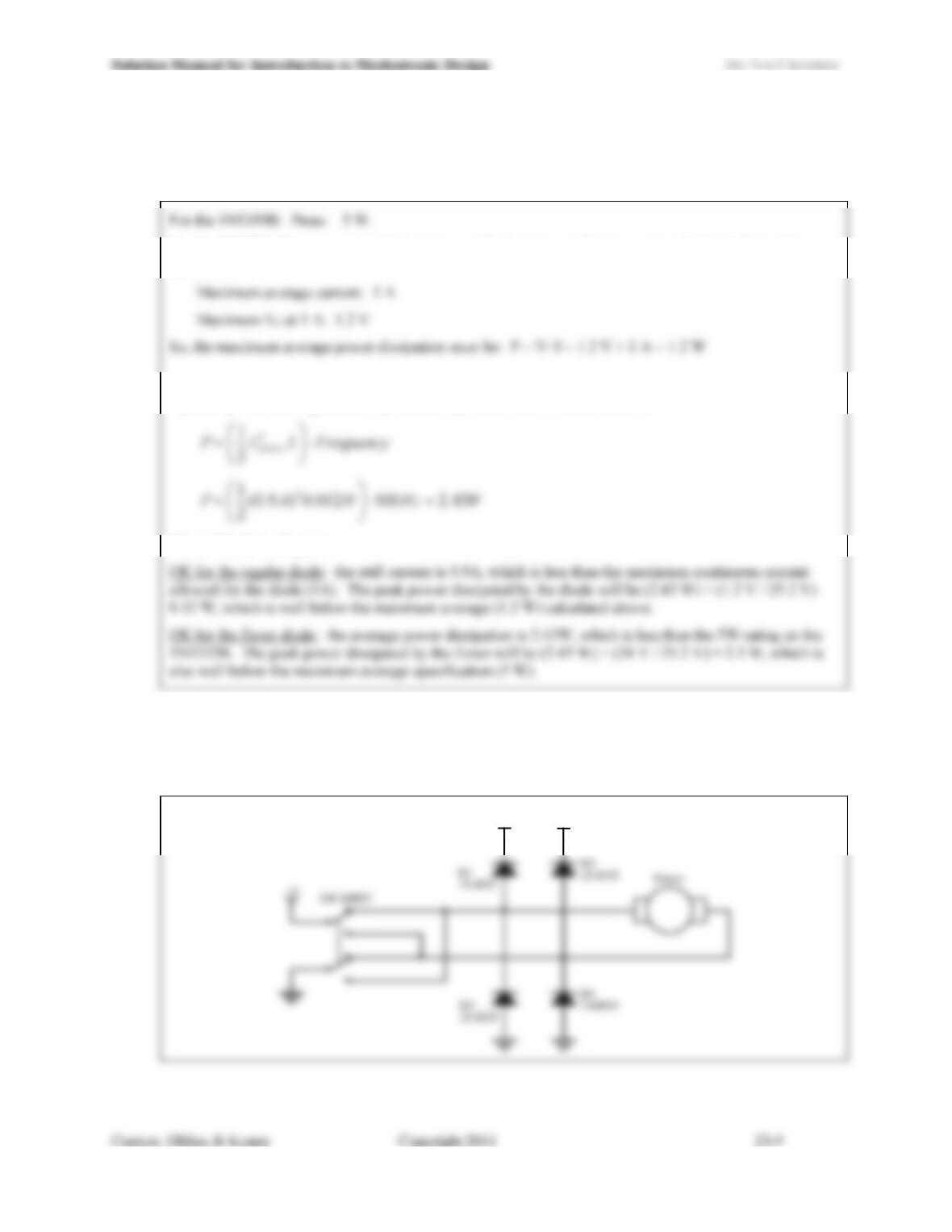
23.7) Design a circuit that performs bi-directional control of a DC motor that uses only the following
components: a 2-position, ON-ON type, double-pole, double-through (DPDT) switch; a DC motor; and
standard diode(s). Show a wiring diagram of your circuit and be sure to include kickback protection with
the standard diodes.
+V
+V
23.8) When implementing PWM in a circuit using a 12 V power supply, what is the average output voltage when
the duty cycle is 42%? If the output voltage is to be increased so that its average value is 8.79 V, what
duty cycle is required?
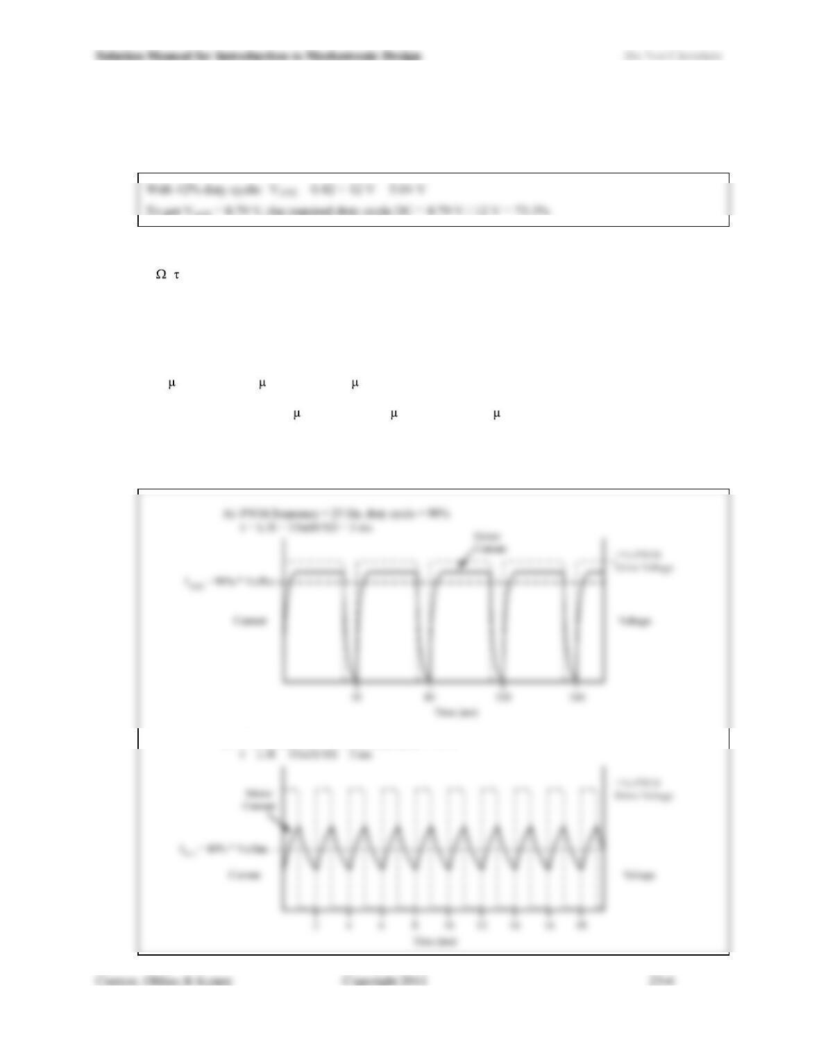
23.9) In a general and qualitative way, sketch the current response vs. time for a motor with L = 15 mH and R =
5 ( = L/R = 3 ms) under PWM control for the following scenarios. Include a sketch of the PWM drive
signal on a separate axis for reference. Do not perform any calculations or analysis to answer these
questions. Assume that the motor is stalled, and that a snubbing technique is used that results in a current
fall time that is roughly equivalent to the rise time.
a) PWM frequency = 25 Hz, duty cycle = 90% (period = 40 ms, on time = 36 ms, off time = 4 ms).
b) PWM frequency = 500 Hz, duty cycle = 40% (period = 2 ms, on time = 0.8 ms, off time = 1.2 ms).
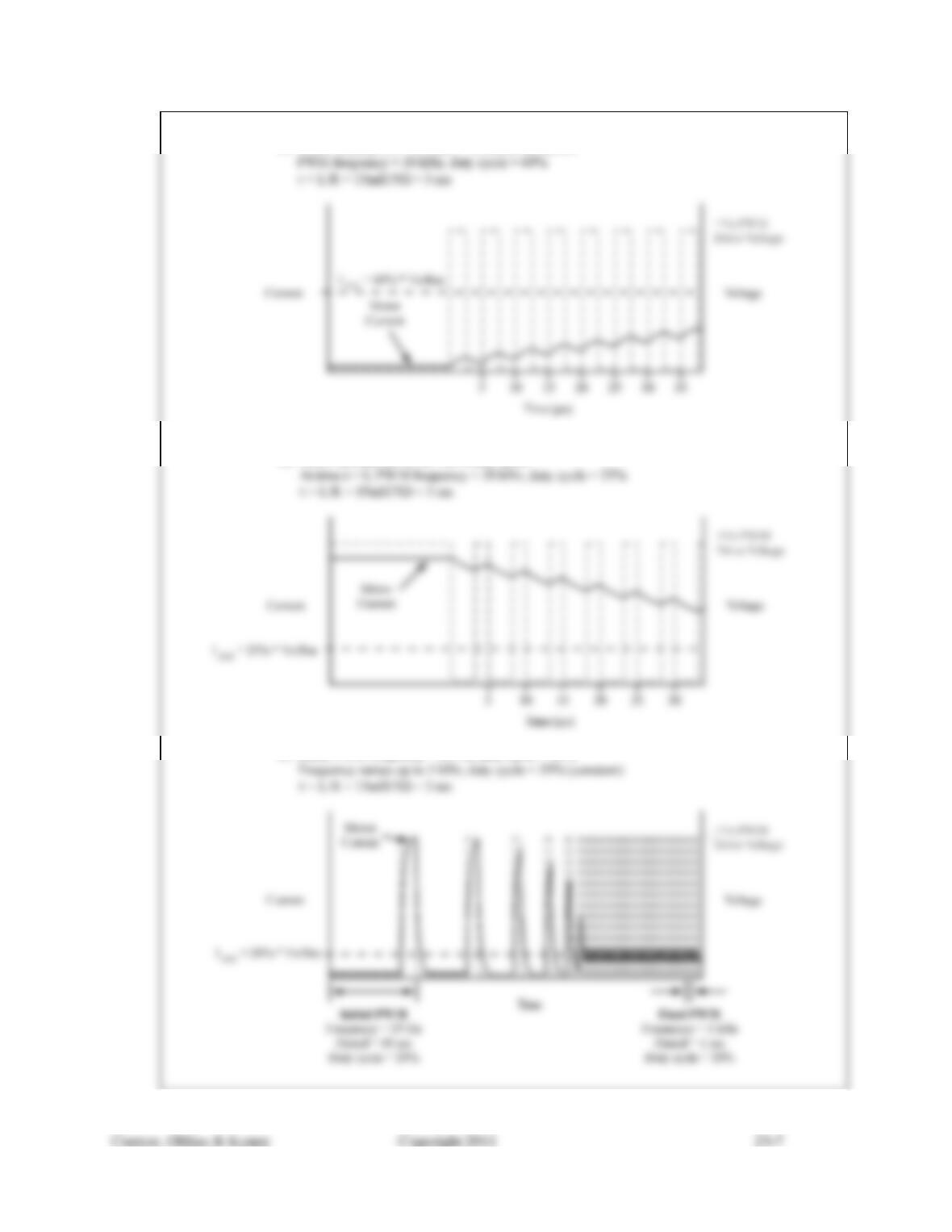
c) The motor is initially off. At time t0, a 20 kHz drive signal is enabled at 60% duty cycle (period = 50
s, on time = 30 s, off time = 20 s). Illustrate the current transient response.
d) The motor is initially running at 100% duty cycle. At time t0, the PWM duty cycle is changed to 25%
at 20 kHz (period = 50 s, on time =12.5 s, off time = 37.5 s). Illustrate the current transient
response.
e) The frequency of the PWM drive signal is increased steadily from 25 Hz to 1 kHz while the duty cycle
is held constant at 20%. (The initial period = 40 ms, initial on time = 8 ms and initial off time = 32 ms.
The final period = 1 ms, final on time = 0.2 ms and final off time = 0.8 ms).
B) PWM frequency = 500 Hz, duty cycle = 40
%
Solution Manual for Introduction to Mechatronic Design Do Not Circulate
C) Motor initially o
f
f. At time t = 0, motor turned o
n
.
D) Motor initially driven at 100% duty cycle.
E) Initial PWM frequency = 25 Hz, duty cycle = 20%
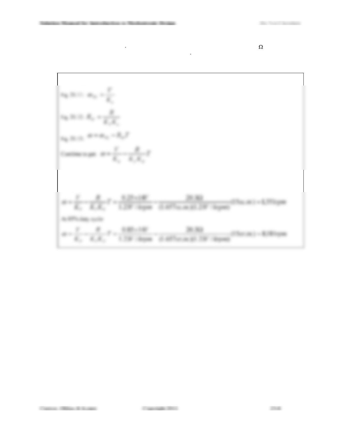
23.10) A motor with KT = 1.657 oz. in./A, KE = 1.230 V/krpm and terminal resistance R = 20.3 is driven at 14
V. How fast will the motor spin under a constant 0.15 oz. in. load if it is driven by PWM with a 25% duty
cycle and a frequency well above the motors electrical time constant? What is the speed if the duty cycle
is increased to 85%?
We can apply Eqs. 20.11, 20.12 and 20.13 and solve directly at each duty cycle:
At 25% duty cycle (and given that the PWM frequency is much higher than the motors electrical time
constant):
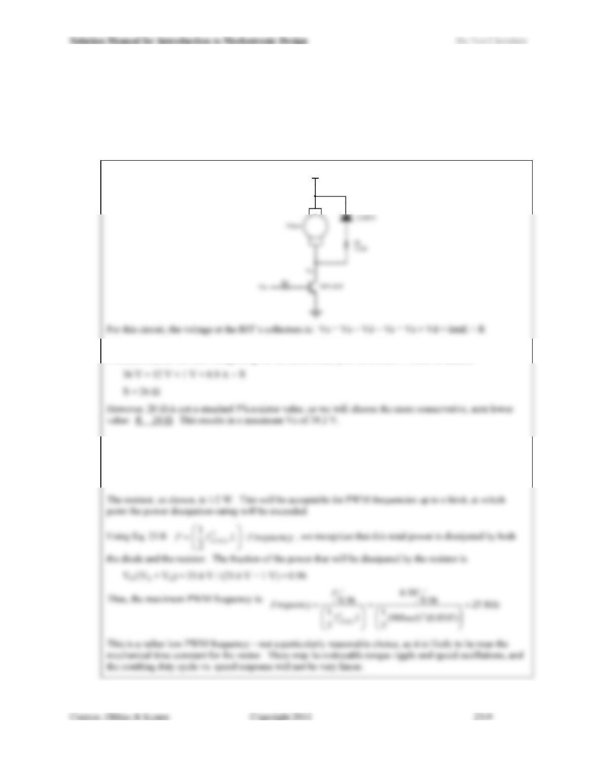
23.11) Design kickback protection circuitry that incorporates a standard diode and a resistor for a motor that has
coil inductance of 50 mH and a stall current of 900 mA when driven by a 12 V power supply. The motor
is controlled by an NPN bi-polar junction transistor (BJT). Limit the inductive kickback voltage spike to
36 V at the collector of the BJT. Draw a schematic diagram of the complete circuit. Under what
conditions can the diode and the resistor safely manage the current and resulting power dissipation? Is the
maximum PWM frequency a reasonable choice?
+12V
With 900 mA flowing in the motor at stall (and hence flowing in the kickback loop when the motor is
switched off) the forward voltage drop for the diode is likely to be around 1V (rule of thumb).
The diode allows for up to 1 A continuous, so 0.9 A intermittently meets its requirements in all
circumstances.