
Solution Manual for Introduction to Mechatronic Design Do Not Circulate
Chapter 21 Noise Grounding and Isolation
21.1) What are the dominant noise coupling channels within typical mechatronic systems?
21.2) True or False: When building a small circuit (1-2 ICs) on a breadboard, it is acceptable to omit the
21.3) True or False: Analog circuits do not require decoupling capacitors.
21.4) True or False: When using shielded wire, the shield should be connected to ground at both ends so that it
provides a common ground connection between the systems.
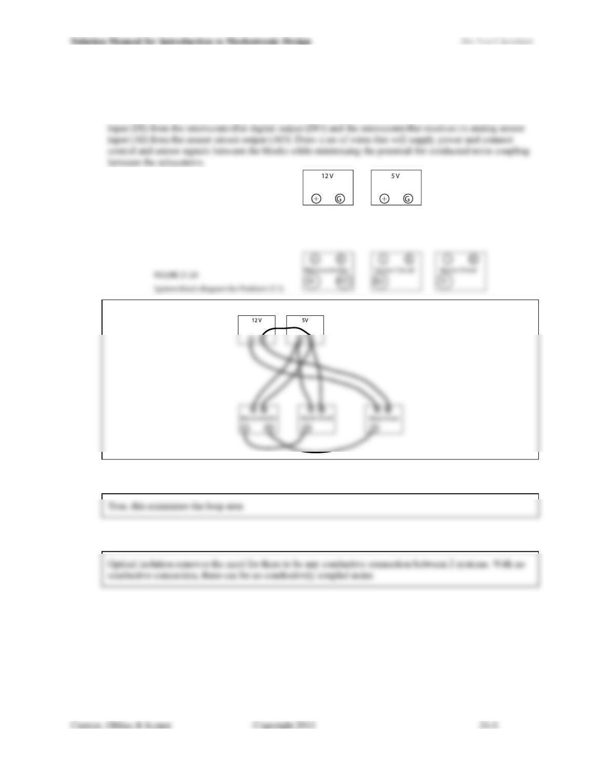
21.5) Figure 21.20 shows the block diagram for a mechatronic system with two power supplies, a
microcontroller, an analog sensor block, and a motor driver block. The microcontroller and the analog
sensor block need to be powered by 5 V, while the motor driver runs on 12 V. The motor driver takes its
21.6) True or False: Simply twisting wires together is an effective way to minimize inductively coupled noise.
21.7) Explain in your own words how optical isolation can reduce conductively coupled noise.
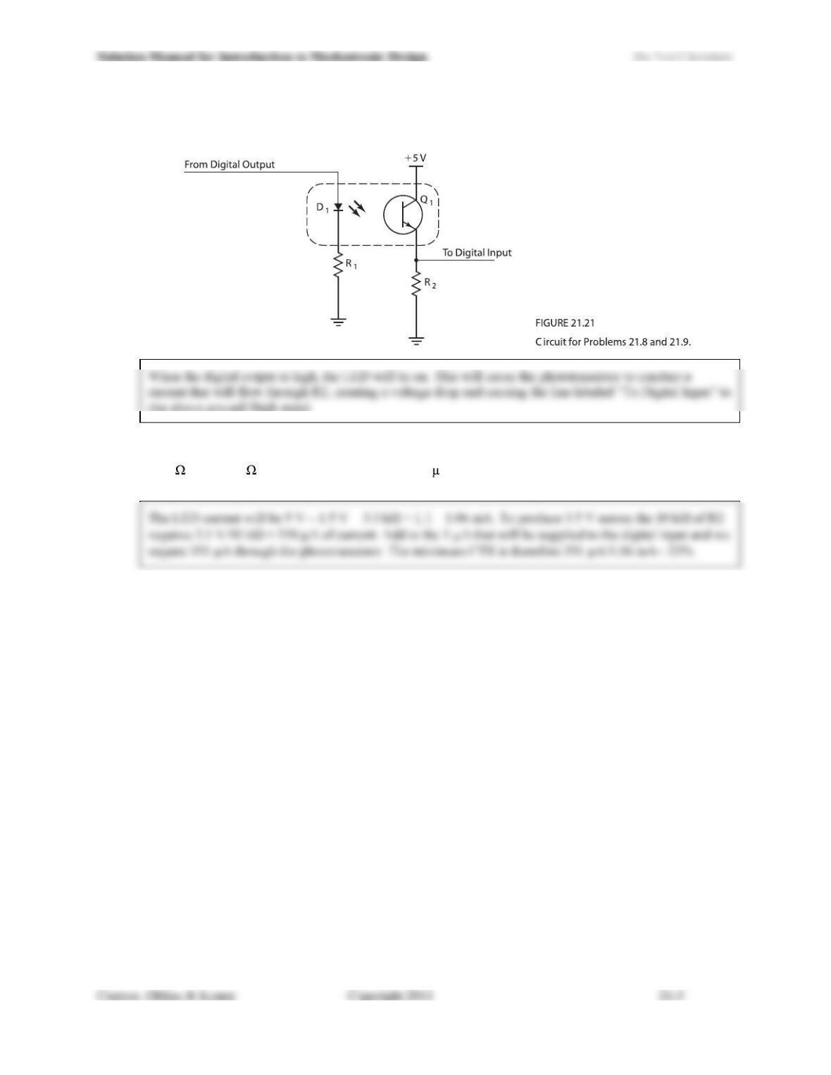
21.8) In the circuit of Figure 21.21, if the digital output is in the high state, would you expect the signal seen by
the digital input to be in a high or low state? Explain why.
.
21.9) In the circuit of Figure 21.21, if the digital output swings between 0 and 5 V, D1 has a Vf of 1.5 V, R1 =
3.3 k , R2 = 10 k , and IIH on the digital input is 1 A, what is the minimum CTR required of the opto–
coupler in order to produce a high-state voltage of 3.5 V at the digital input?
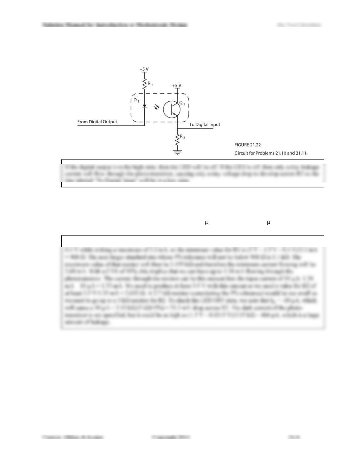
21.10) In the circuit of Figure 21.22, if the digital output is in the high state, would you expect the signal seen by
the digital input to be in a high or low state?
21.11) In the circuit of Figure 21.22, if the digital output connected to the cathode of the diode (D1) swings
between 0.4 V while sinking a maximum of 3.2 mA and 4.5 V while sourcing a maximum of 1 mA, D1 has
a Vf of 1.5 V, the CTR of the opto-coupler is 50%, and the digital input connected to the collector of the
photo-transistor has specifications of VIH = 3.5 V, IIH = 10 A, VIL = 1.5 V, IIL = -10 A, choose values for
R1 and R2 that will result in acceptable input voltages to the digital input.
The ON state of the LED is most critical here and that is the low state of the output. The output will be at