Solution Manual for Introduction to Mechatronic Design Do Not Circulate
Chapter 20 Voltage Regulators, Power Supplies and Batteries
20.1) A 5 V LDO voltage regulator has a maximum dropout voltage specification of 0.21 V. If it is to provide a
stable output of 5 V, what is the minimum voltage that must be supplied at the input of the regulator?
A voltage of at least Vout + VDO must be supplied:
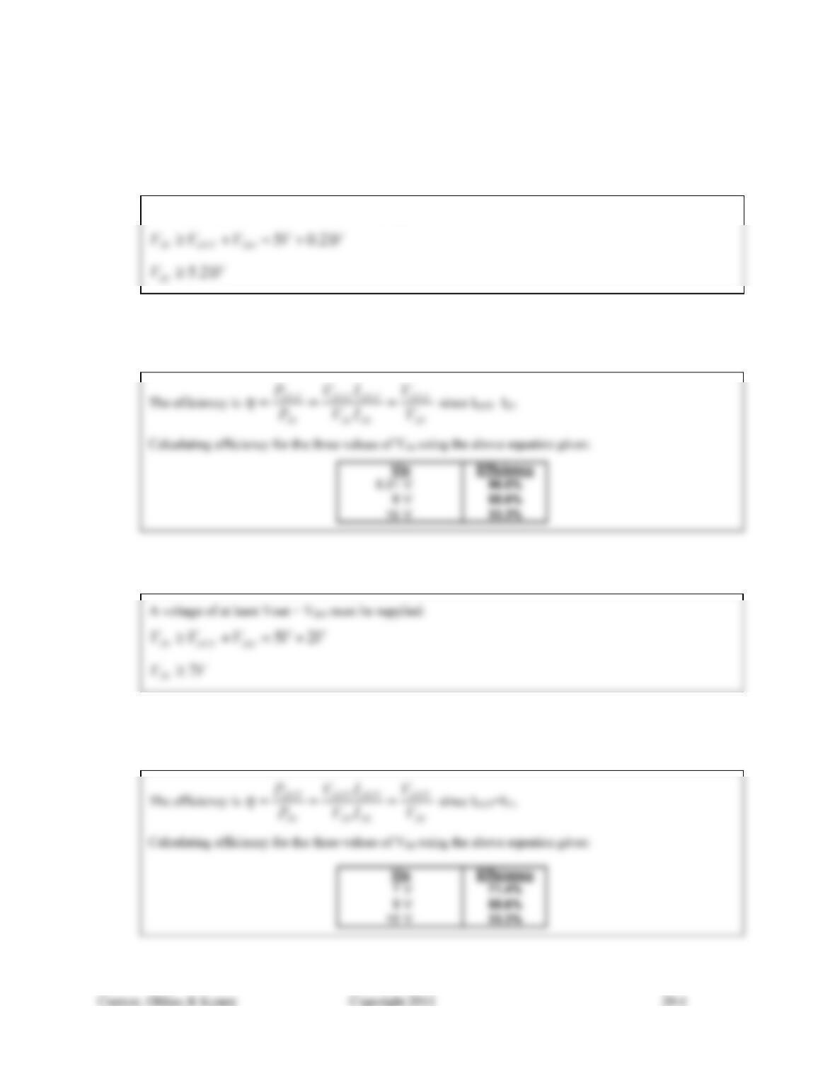
20.2) What is the efficiency of the LDO voltage regulator described in Problem 20.1 if the input voltage is the
minimum voltage that results in a regulated 5 V output? What is the efficiency if the input voltage is
increased to 9 V? 15 V?
20.3) An LM7805 linear voltage regulator is used to provide a stable output voltage of 5 V. What is the
minimum voltage that must be supplied at the input of the regulator to ensure the output is at 5 V?
20.4) What is the efficiency of the LM7805 voltage regulator described in Problem 20.3 if the input voltage is
the minimum voltage that results in a regulated 5 V output? What is the efficiency if the input voltage is
increased to 9 V? 15V?
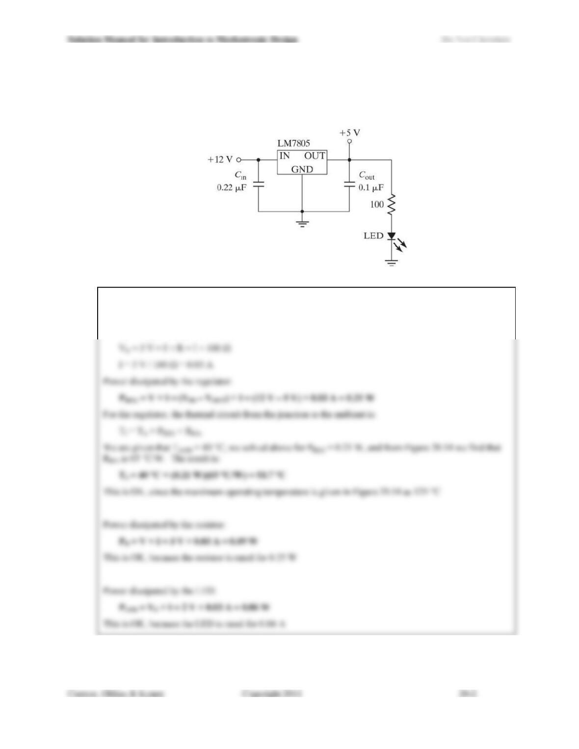
20.5) For the circuit shown in Figure 20.49, the LED has a forward voltage drop Vf = 2 V. How much heat is
dissipated in the regulator? In the resistor? In the LED? If the ambient temperature is 40°C, is the
LM7805 operating within specifications (use the specifications in Figure 20.14)? If the resistor is rated at
1/4 W and the LED is rated for a maximum continuous current of 40 mA, are these components operating
within specifications?
Figure 20.49: Schematic for circuit in Problem 20.5.
The current that flows in the circuit is given by:
VOUT VR VLED = 0
VR = VOUT VLED = 5 V 2 V = 3 V
20.6) A switching voltage regulator circuit operates at 85% efficiency, and its input voltage is 24 V. If it
provides a regulated output of 12 V at 2 A, what is the average current flowing into the input? How much
power does the regulator circuit dissipate under these conditions?
Efficiency is defined as:
IN
OUT
P
P
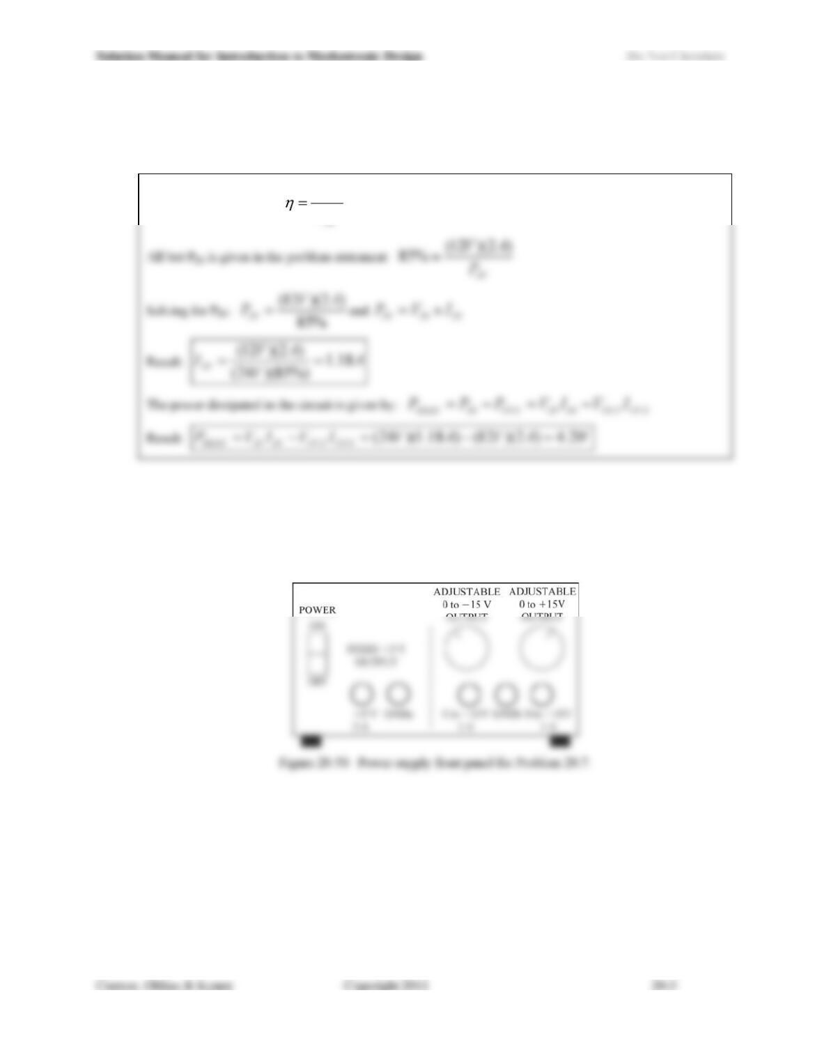
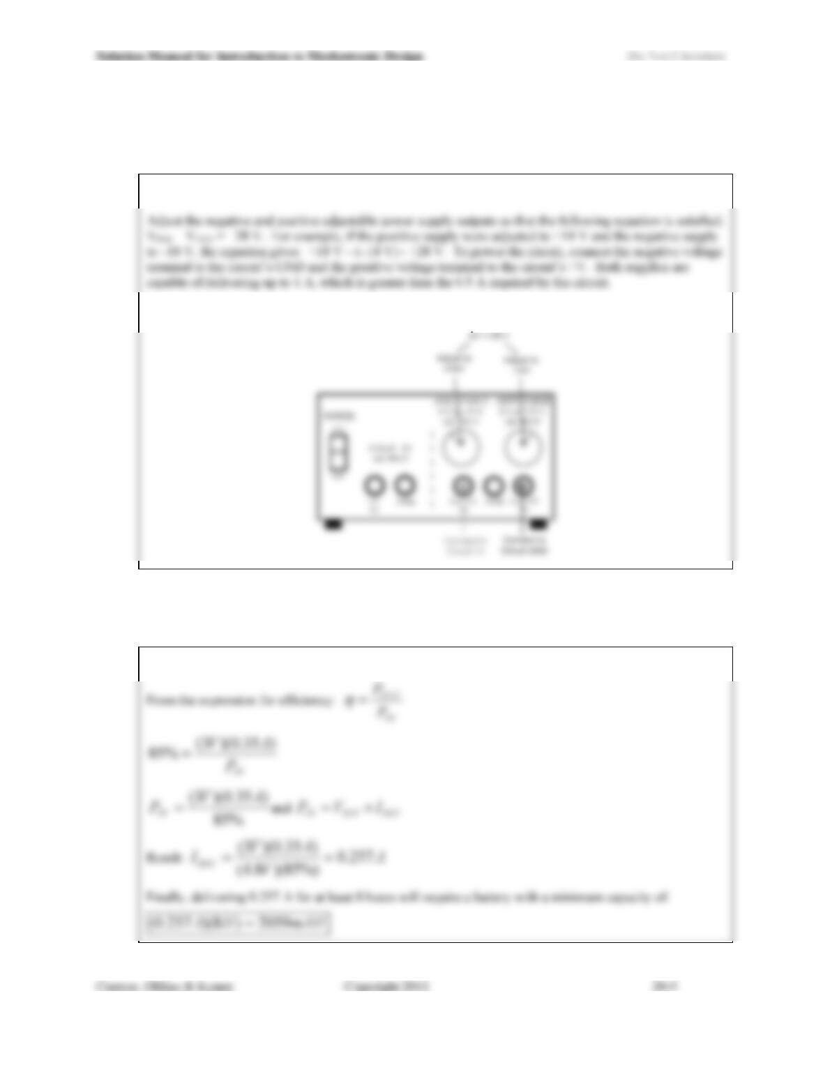
20.7) Your bench-top laboratory power supply has three regulated outputs. The first is a fixed +5 V output,
capable of supplying up to 3 A. The second is an adjustable 0 to +15 V output that can supply up to 1 A,
and the third is an adjustable 0 to -15 V output, also capable of up to 1 A (Figure 20.50). The ground for
the fixed output is independent of the ground for the adjustable outputs. To power a new prototype circuit,
you need 18 V and a maximum of 0.8 A. Can you use this power supply to power the circuit? If so, show
how it will be configured. If not, explain why not.
Solution Manual for Introduction to Mechatronic Design Do Not Circulate
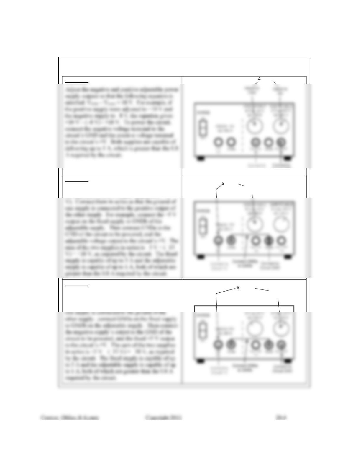
YES, you can use this power supply to power the proposed circuit. There are 3 ways this could be done:
Option 1:
Circuit GND
Circuit +V
V = 18 V
Option 2:
Use the fixed +5 V supply in combination with
the adjustable positive supply (adjusted to +13
Adjust to
+13V
V = 18 V
Option 3:
Use the fixed +5 V supply in combination with
the adjustable negative supply (adjusted to -13
V). Connect them in series so that the ground of
ADJUSTABLE
ADJUSTABLE
Adjust to
-13V
V = 18 V
20.8) You revise the circuit you created in Problem 20.7, and now it requires 28 V and as much as 0.5 A of
current. Can you use the power supply described in Problem 20.7 for this new circuit? If so, show how
you will configure it to meet the circuits requirements. If not, explain why not.
YES, you can use this power supply to power the proposed circuit.
Configure the power supply and connect it as shown below:
20.9) Determine the minimum battery capacity (in mAH) required to power a portable device that consumes an
average of 350 mA at 3 V for at least 8 hours. The battery voltage is 4.8 V and the device incorporates a 3
V regulator that operates at 85% efficiency.
Under the conditions given, the battery is required to deliver the following current:
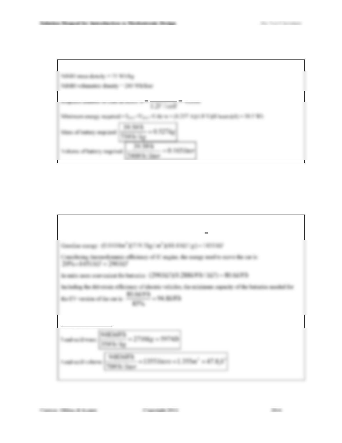
20.10) Using Table 20.3, what is the minimum possible volume and mass of the NiMH battery pack needed to
satisfy the requirements of Problem 20.9?
From Table 20.3:
V
8.4
20.11) A particular car uses an internal combustion engine with 20% thermodynamic efficiency for locomotion,
carries 12 gallons of gasoline (energy density = 44 MJ/kg) and gets 25 miles per gallon. If all other factors
are assumed to be equal, what mass (in kg) and volume (in m3) of lead-acid batteries would be needed to
provide an equivalent range for an electric version of the vehicle? What volume and mass are required if
Li-ion batteries are used instead? Assume that the overall energy conversion efficiency for an electric
vehicle is 85%.
First, determine the energy content of the gasoline used by the internal combustion engine:
Gasoline volume: 33 0454.0)/001.0)(/784.3)(12( mlitermgallitersgal
For lead-acid batteries:
Solution Manual for Introduction to Mechatronic Design Do Not Circulate
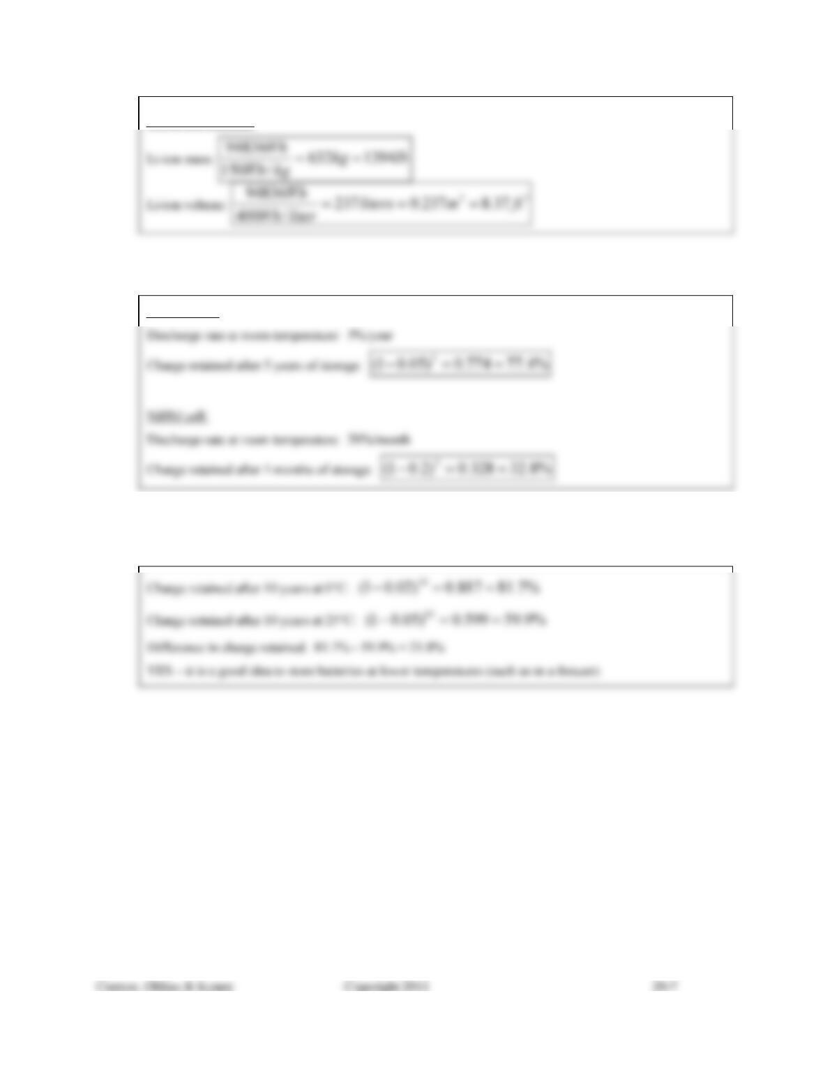
For Li-ion batteries:
20.12) What fraction of an alkaline cells original charge remains if it is stored at room temperature for 5 years?
What fraction of a NiMH cells original charge remains if stored at room temperature for 5 months?
Alkaline cell:
20.13) A given batterys self-discharge rate is 2% per year at 0°C and 5% per year at 25°C. How much more
charge will the battery stored at 0°C hold than an identical battery stored at 25°C after 10 years? Is it a
good idea to store batteries in a freezer?
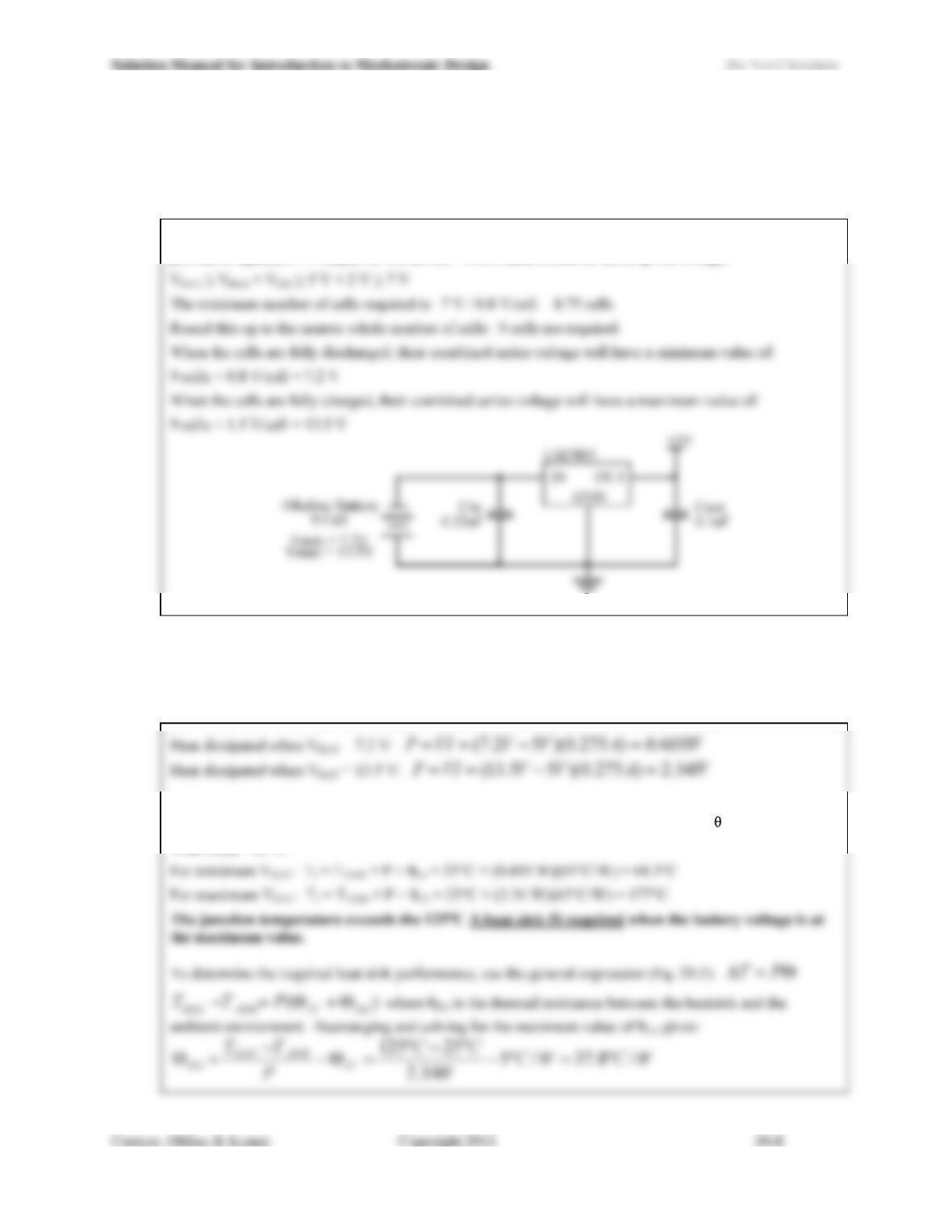
20.14) Design a circuit that uses alkaline cells and an LM7805 linear voltage regulator to provide a portable
device with 5 V. Alkaline cells have a terminal voltage of 1.5 V when new (fully charged), and an end
voltage of 0.8 V. Design your circuit so that it provides a regulated output voltage of 5 V across the full
range of the cells terminal voltage (0.8 V to 1.5 V).
The number of cells needed is determined by the input voltage requirement of the LM7805 in order for it to
provide a regulated 5 V output for the device. This is determined by the drop-out voltage:
20.15) For the circuit you designed in Problem 20.14, calculate the resulting heat dissipation in the LM7805 under
the full range of possible cell terminal voltages when delivering 275 mA. For an ambient temperature of
25°C, is a heat sink required? If so, what is the maximum thermal resistance that the heat sink could have
to satisfy the requirements? If not, what is the maximum allowable ambient temperature?
From Figure 20.14, we see that maximum junction operating temperature is 125°C and JA = 65°C/W.
With TAMB = 25°C: