Solution Manual for Introduction to Mechatronic Design Do Not Circulate
Chapter 19 A-to-D and D-to-A Converters
19.1) You wish to sample a signal with frequency content between 0 and 1 kHz with an A/D converter. What is
the minimum sampling rate required to ensure that aliasing will not inhibit your ability to accurately
interpret the data?
19.2) You wish to use an 8-bit A/D converter with Vref = 5 V to measure a signal (amplitude = 2 Vpp, frequency
= 1 kHz) that includes substantial noise (amplitude 0.5 Vpp, frequency > 5 kHz). You will sample the
signal at a rate of 10 kHz. Design an anti-aliasing filter that prevents the noise from affecting your
readings, and alters the amplitude of the 1 kHz signal by 20% or less.
Our objective is to attenuate the noise to below 1 LSB of the converter, which is
In order to reduce the effect of the filter on the 1 kHz signal, one viable approach would be to select an n-
order low-pass RC filter with a corner frequency above 1 kHz, for example ~3.5 kHz. With this as a
starting point, a 6th-order filter can be constructed that achieves the required attenuation of the signal and
the noise.
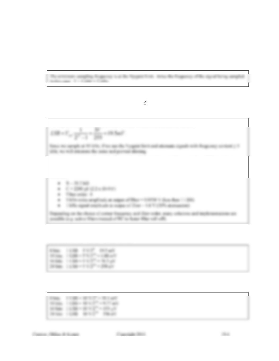
19.3) For an A/D converter with VRL = 0 V and VRH = 5 V, what is the value of an LSB if the resolution of the
converter is 8 bits? 10 bits? 16 bits? 24 bits?
19.4) For an A/D converter with VRL = -5 V and VRH = 5 V, what is the value of an LSB if the resolution of the
converter is 8 bits? 10 bits? 16 bits? 24 bits?
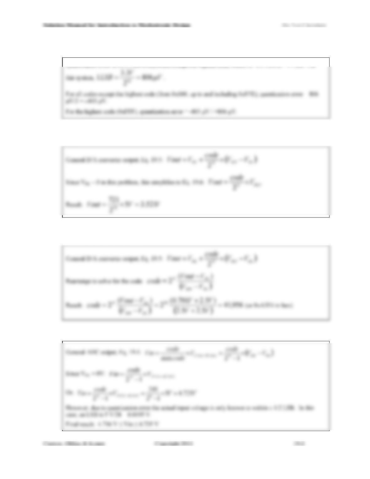
19.5) For a 12-bit A/D converter with Vref = 3.3 V, what is the uncertainty contributed by quantization error?
Quantization error is ±1/2 LSB everywhere except the highest code, which is -1/2 LSB or +1 LSB. For
19.6) For a 10-bit D/A converter with VRL = 0 V and VRH = 5 V, what is the output voltage if the input code is
721?
19.7) For a 16-bit D/A converter with VRL = -2.5 V and VRH = 2.5 V, what input code would be needed to
produce an output of 0.701 V?
19.8) For an 8-bit A/D converter with Vref = 5 V, what is the input voltage if the output code is 241 (decimal)?
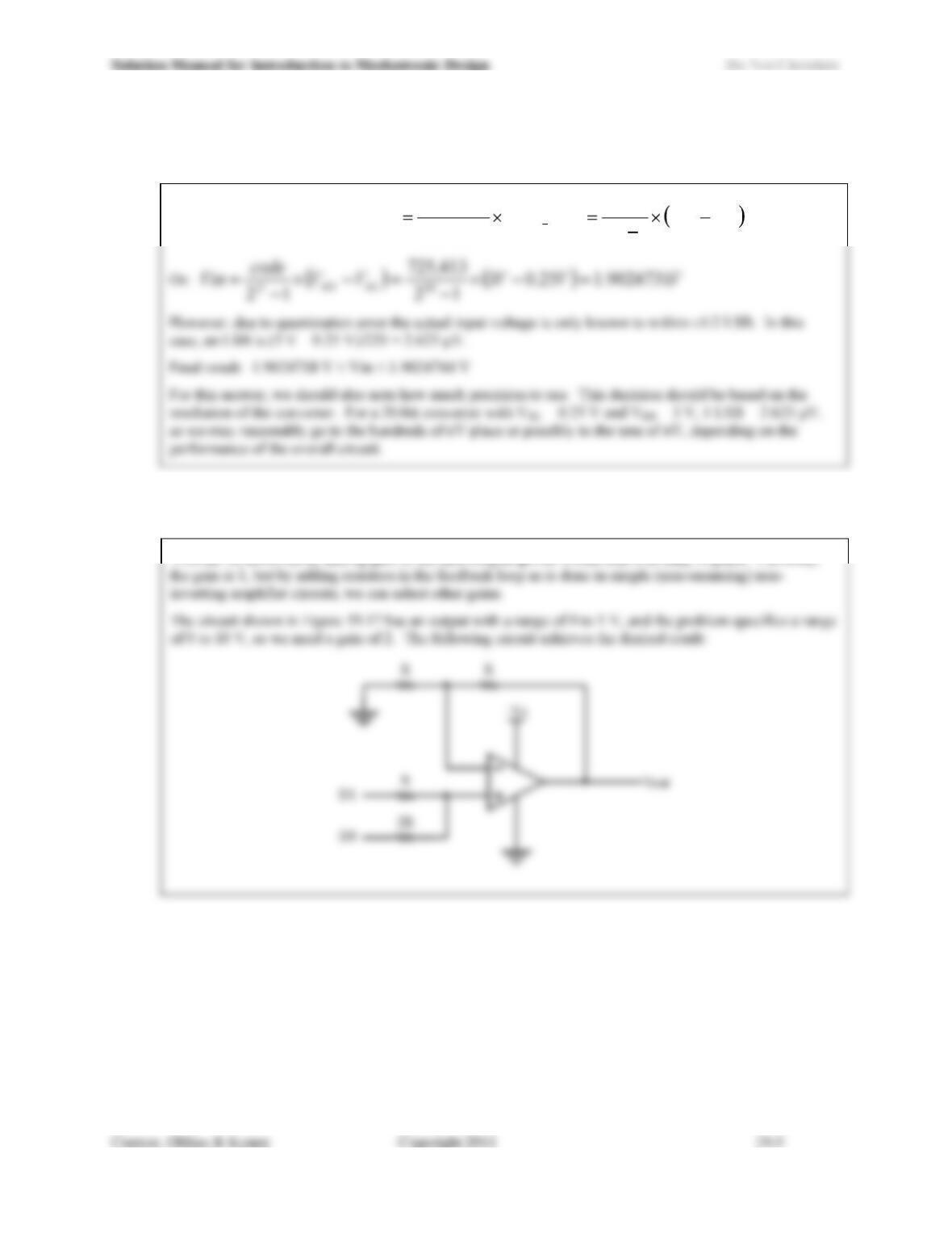
19.9) For a 20-bit A/D converter with VRL = 0.25 V and VRH = 3 V, what is the input voltage if the output code is
725,413 (decimal)?
General ADC output, Eq. 19.4: RLRH
N
SCALEFULL VV
code
V
code
code
Vin 12max
19.10) Without adding any op-amps, how could you redesign the circuit shown in Figure 19.17 so that the output
of the summing D/A converter ranges from 0 to 10 V?
This can be achieved by adding gain to the summing amplifier circuit that is already in place. Currently,
19.11) Using the Internet, find examples of a flash A/D converter, a SAR A/D converter and a sigma-delta A/D
converter from the following manufacturers: Maxim Integrated Products and Texas Instruments. Create a
table that compares their resolution, maximum sample rates, and price. Hint: it may simplify your search
if you begin by locating the manufacturers data converter selection guides.
This question requests that students perform research on the Internet and report their findings. There is a
* The TLC5540 uses a half-flash architecture
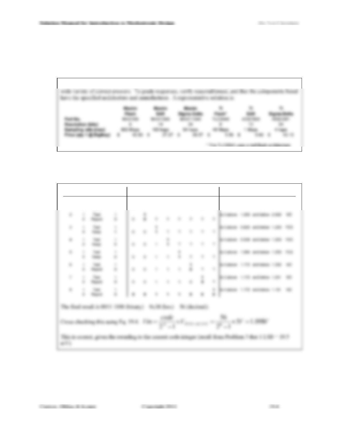
19.12) Construct a table like the one shown in Figure 19.28 that illustrates each of the steps for an 8-bit SAR A/D
converter if the input voltage is 1.095 V and Vref = 5 V. What is the output code when the conversion is
complete?
Test Clock
Bit
Status
Comparator
Output
MSB
D7 D6 D5 D4 D3 D2 D1
LSB
D0
1 1 Test 1 1Is it above 2.5 and below 5 NO
0 Reject 0 0? ? ? ? ? ? ?
Tests