Solution Manual for Introduction to Mechatronic Design Do Not Circulate
Chapter 18 Digital Logic and Integrated Circuits
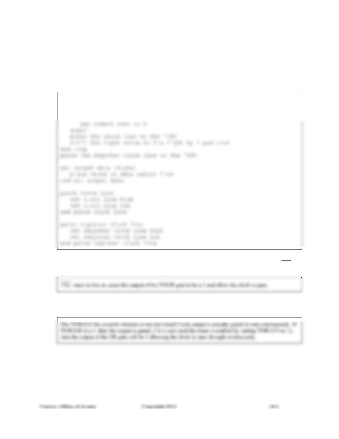
18.1) Write the pseudo-code to bit-bang three output lines to use a 74HC595 to create an extra eight output
lines. Structure the code with a high level function that will take an 8-bit value and transfer it to the outputs
of the 74HC595. Also write the pseudo-code for lower level functions that will isolate the interaction with
the hardware and therefore make it easier to change which output ports and bits are being used.
Loop 8 times
if LSB of input value is 1
set output data to 1
else
18.2) In Figure 18.5, if TMR1ON, TMR1GE and T1GINV are all true, what state must be present on the GT1
pin in order for the Clock Input to be passed to the Gated Clock?
18.3) In Figure 18.5, what is the function of the TMR1GE bit? (Describe the difference in behavior of the logic
based in its 2 states.)
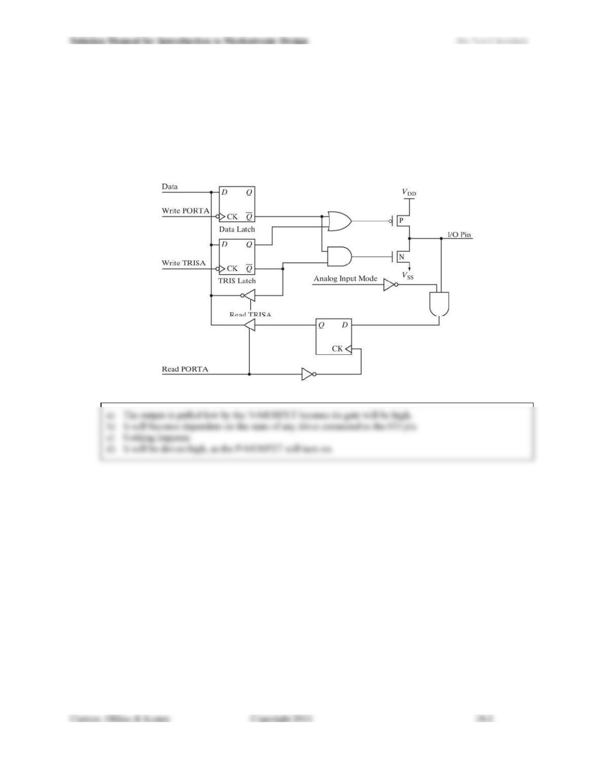
18.4) Referring to Figure18.29, with Analog Input Mode = 0, Read TRISA = 0, Read PORTA = 0:
a) If all Q outputs are 0, what is the state on the I/O pin (high, low, indeterminate)?
b) If Data = 1, Write PORTA = 0, and Write TRISA pulses high, then low, what will happen to the state
of the I/O pin?
c) From the conditions left after part b), if Data = 1, Write TRISA = 0, and Write PORTA pulses high,
then low, what will happen to the state of the I/O pin?
d) From the conditions left after part c), if Data = 0, Write PORTA = 0, and Write TRISA pulses high,
then low, what will happen to the state of the I/O pin?
Figure 18.29 Figure for circuit in Problem 18.4.
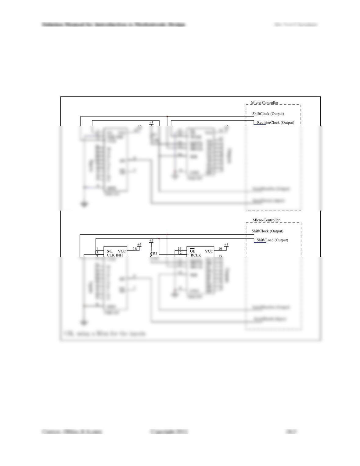
18.5) As is all too often the case, the microcontroller for your project has come up short of input and output
lines. You have four programmable direction I/O lines available and you need four inputs and four outputs.
Design a circuit that will expand the four available lines into the eight required lines. Changes to the
expansion ports should mimic the behavior of ordinary ports in that reads of the input port should return
the state of all four input bits at the same instant in time and updates of the four output bits should all
appear simultaneously on those 4 bits. Show the directions for each of the four port lines that you use.
OR
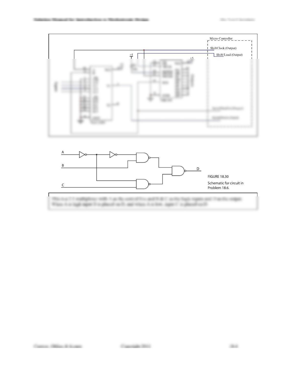
18.6) What named function does the circuit in Figure 18.30 implement?
18.7) Write the pseudo-code to use the circuit from Problem 18.5 to read in the four inputs and write the four
outputs. Your code should provide any required initialization function and a function to read the lines and a
function to write the lines.
Code for the first solution (uses serial data out line to control Shift/Load on input 165)
void InitExpansionPortLines(void)
Begin loop to shift new data in
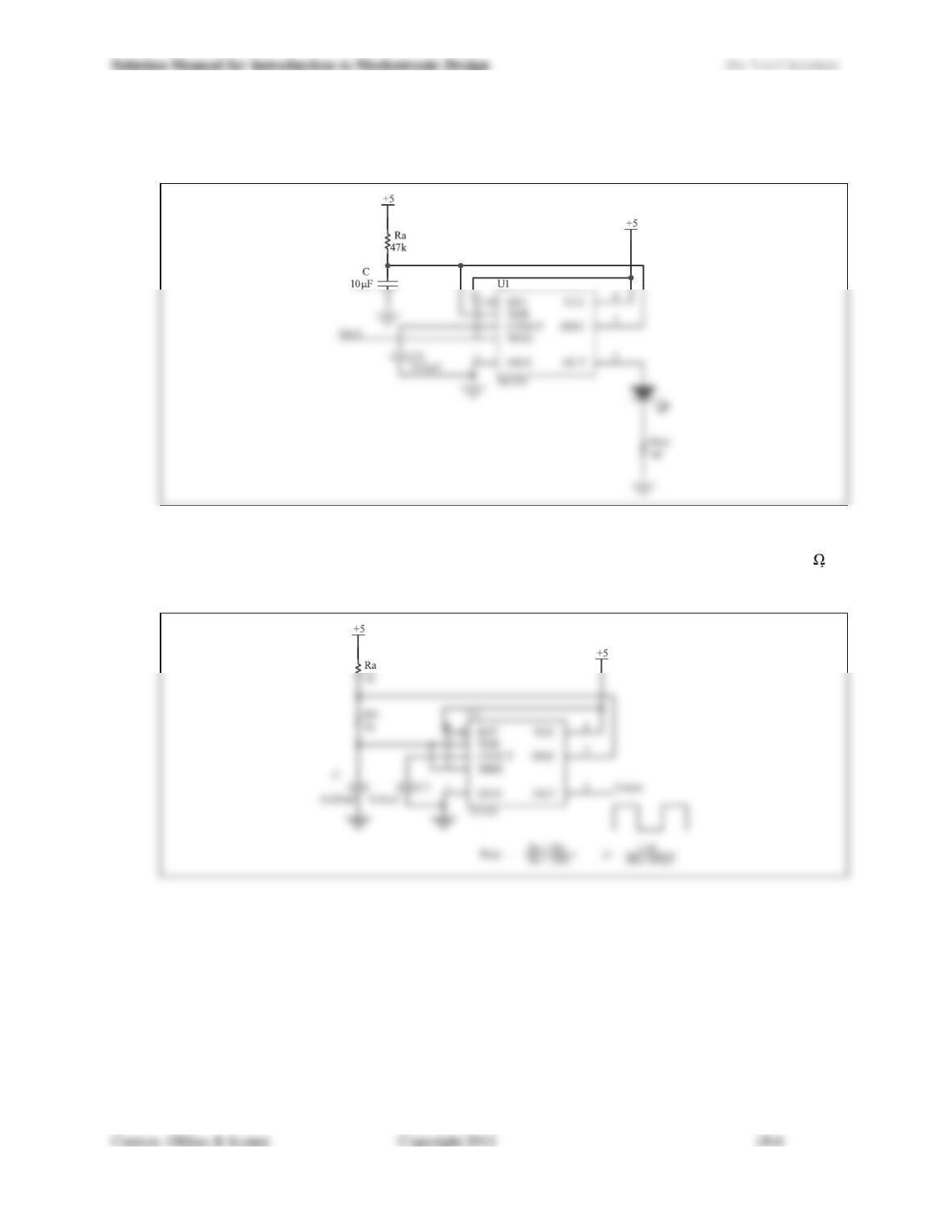
18.8) Design a circuit using a 555 that will light an LED with 20 mA of forward current for a period of 0.5 s for
every 1 ms long low-going pulse from a 74HC04.
18.9) Using a 555, design an astable multivibrator. Shoot for a frequency of about 10 kHz (± 10%) and a duty
cycle (ratio of high time to total time) of about 50% (± 10%). Do not choose Ra too small (less than 1 k
or it won’t work in practice. Include the calculations that you did to set the frequency and duty cycle. In
your answer, include a schematic for the circuit, including component values and types.
18.10) Write pseudo-code to control the circuit of Figure 18.19. The top level function should take a symbolic
constant (Light0-Light7, All_OFF) to determine which of the LEDs will be lit.
Assume that the constant All_OFF is greater than 7