Solution Manual for Introduction to Mechatronic Design Do Not Circulate
Chapter 17 Digital Outputs and Power Drivers
17.1) If you wanted to drive an LED to the maximum possible brightness with the output of a 7400, would you
arrange it so that the LED was on when the 7400’s output was in the low state or the high state? Use worst-
case design principles and quote specifications from Figure 17.2 to support your answer.
17.2) If you wanted to drive an LED to the maximum possible brightness with the output of a 74HC04 would
you arrange it so that the LED was on when the 74HC04’s output was in the low state or the high state?
Use worst-case design principles and quote specifications from Figure 17.3 to support your answer.
17.3) If an LED is to be driven from either a 7400 or a 74HC04 which would you expect to produce the greater
LED light output? Use worst-case design principles and quote specifications from Figures 17.2 and 17.3 to
support your answer.
17.4) If the outputs from two LM339A devices are to be used in a wired OR configuration to drive a single input
of an MC9S12 family device (use the specifications from Figures 17.8 and 16.1) what are the minimum
and maximum values for the pull-up resistor? Choose from among commercially available 5% tolerance
resistors.
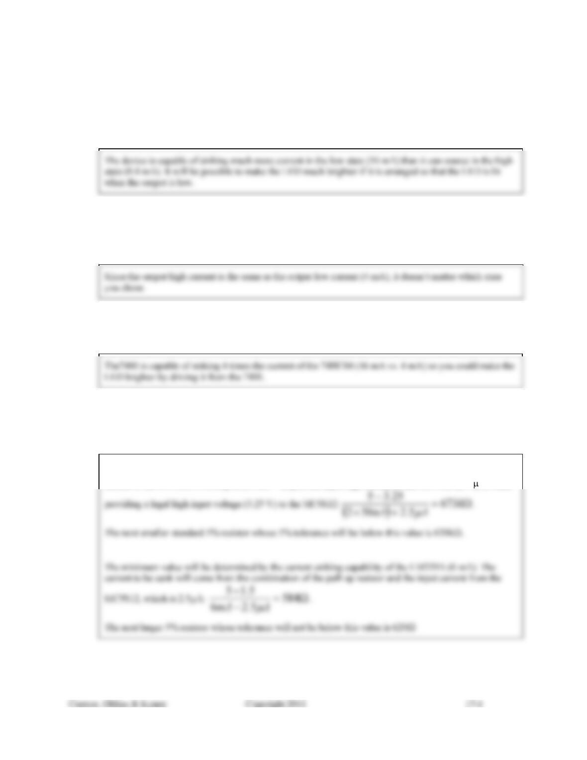
The maximum pull-up value will occur when the output is in the high state and it must provide the leakage
current to the two LM339A outputs (50 nA × 2) plus the input high current to the MC9S12 (2.5 A) while
17.5) Using the ULN2003A specifications from Figure 17.12, what is the minimum required input voltage to be
able to support an output current of 250 mA?
17.6) For the conditions specified in Problem 17.5, what is the expected output voltage at the collector of the
ULN2003A?
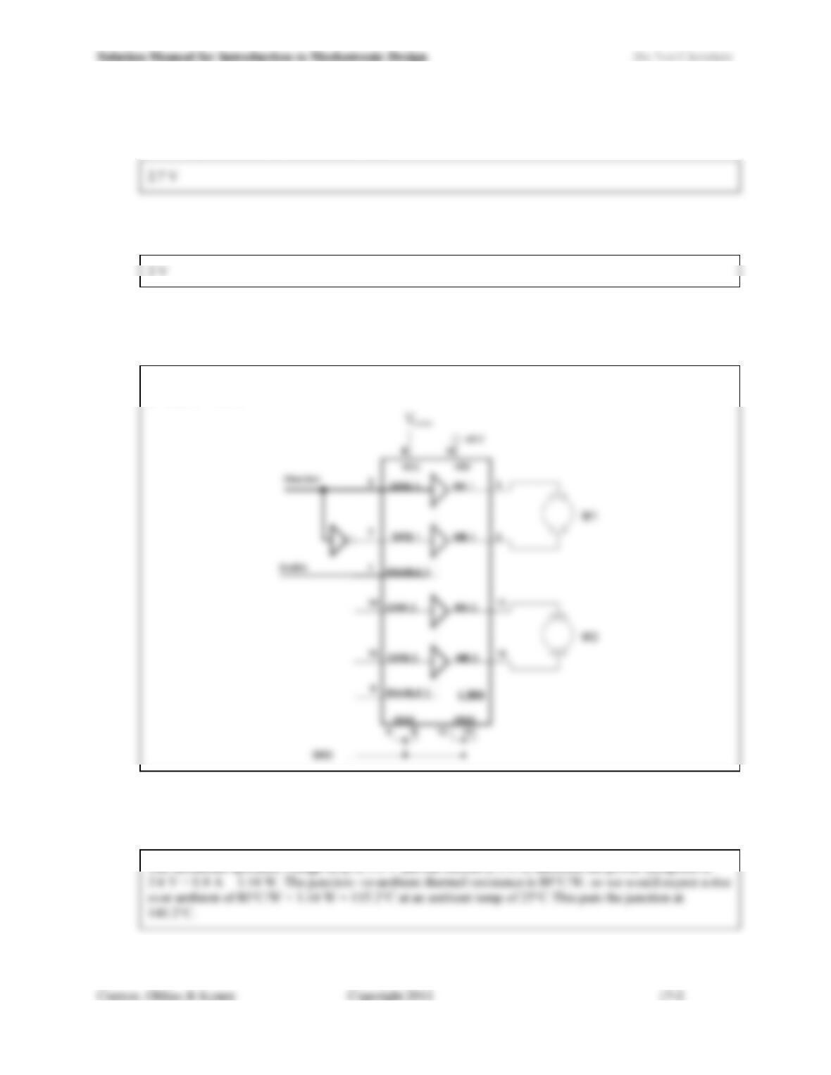
17.7) If an L293B powered by 5 V is used to drive a motor whose stall current is 1 A, what is the minimum
voltage that you would expect to see across the terminals of the motor under stall? Use the specifications
from Figure 17.17, and include a schematic of the circuit with your answer.
Since max VCEsatH and VCEsatL are both 1.8V, the guaranteed minimum voltage available at the motor is:
5 – 3.6 V = 1.4 V.
17.8) If an L293B is used without a heat sink to drive a motor whose stall current is 400 mA, what is the
expected maximum junction temperature if the motor is stalled indefinitely? Assume the maximum
specified voltage drop across the L293B and an ambient temperature of 25°C.
The maximum specified voltage drop is 3.6 V and the current is 0.4 A, therefore the power dissipated is
Solution Manual for Introduction to Mechatronic Design Do Not Circulate
17.9) If, under the same conditions as Problem 17.8, the heat sink shown in Figure 17.21 were added to the
L293B, what will the expected maximum junction temperature be?
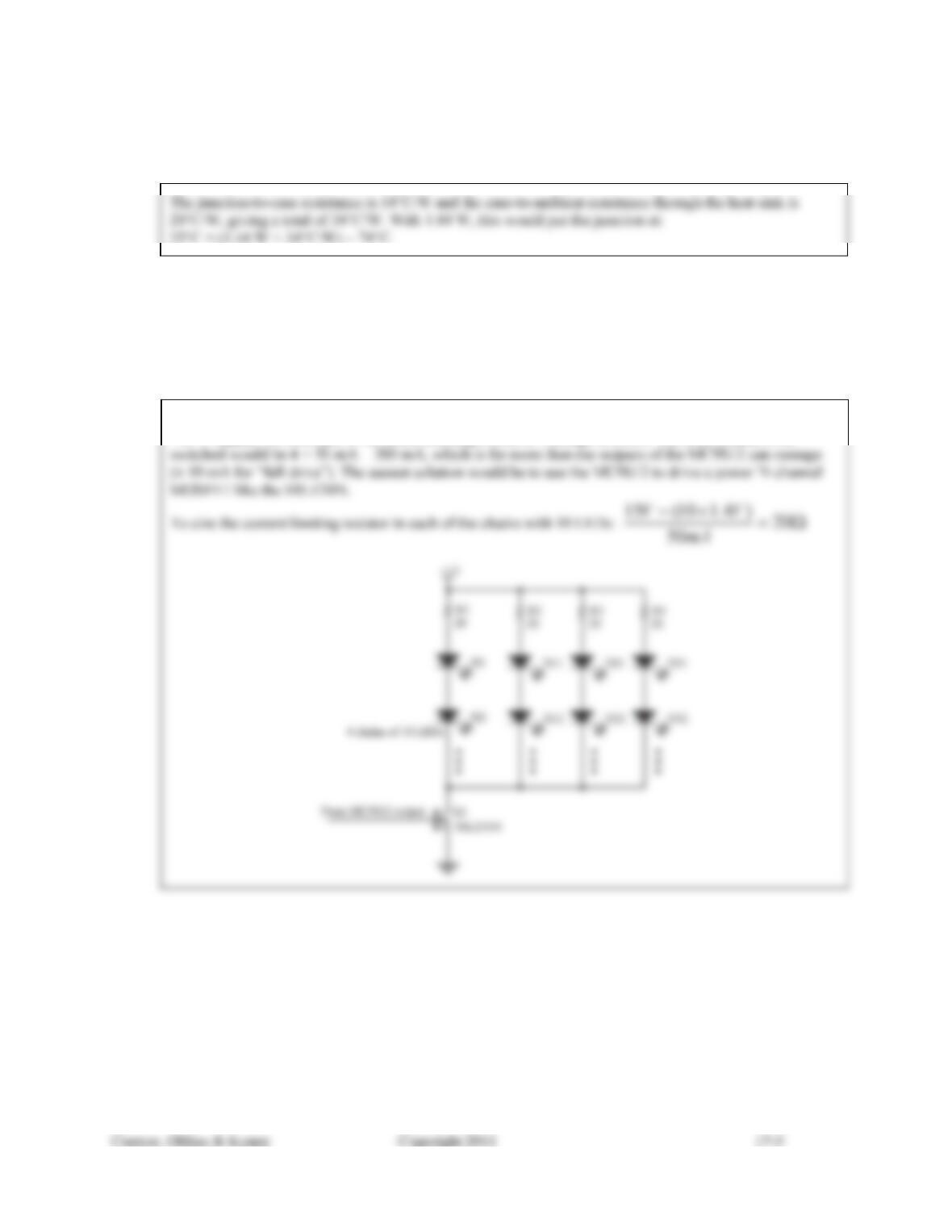
17.10) In a particularly bright smart product, the designer needs to turn on a set of 40 IR LEDs (Vf = 1.4 V), each
carrying 50 mA. Design a circuit that performs this task using the output from a single MC9S12 family
device (use the specifications in Figure 16.1) as the drive signal and a minimal number of other
components (the number of active elements should not exceed 3). You have +5 V, +12 V, and +15 V
power supplies available. Show, by calculations and reference to the relevant specifications, that your
design does not exceed the capabilities of any of the devices involved.
We will minimize the number of components if we put as many of the LEDs in series as possible. With a
+15 V supply, we could put 10 in series, yielding a total of 4 strings of LEDs. The total current to be