Solution Manual for Introduction to Mechatronic Design Do Not Circulate
Chapter 16 Digital Inputs and Outputs
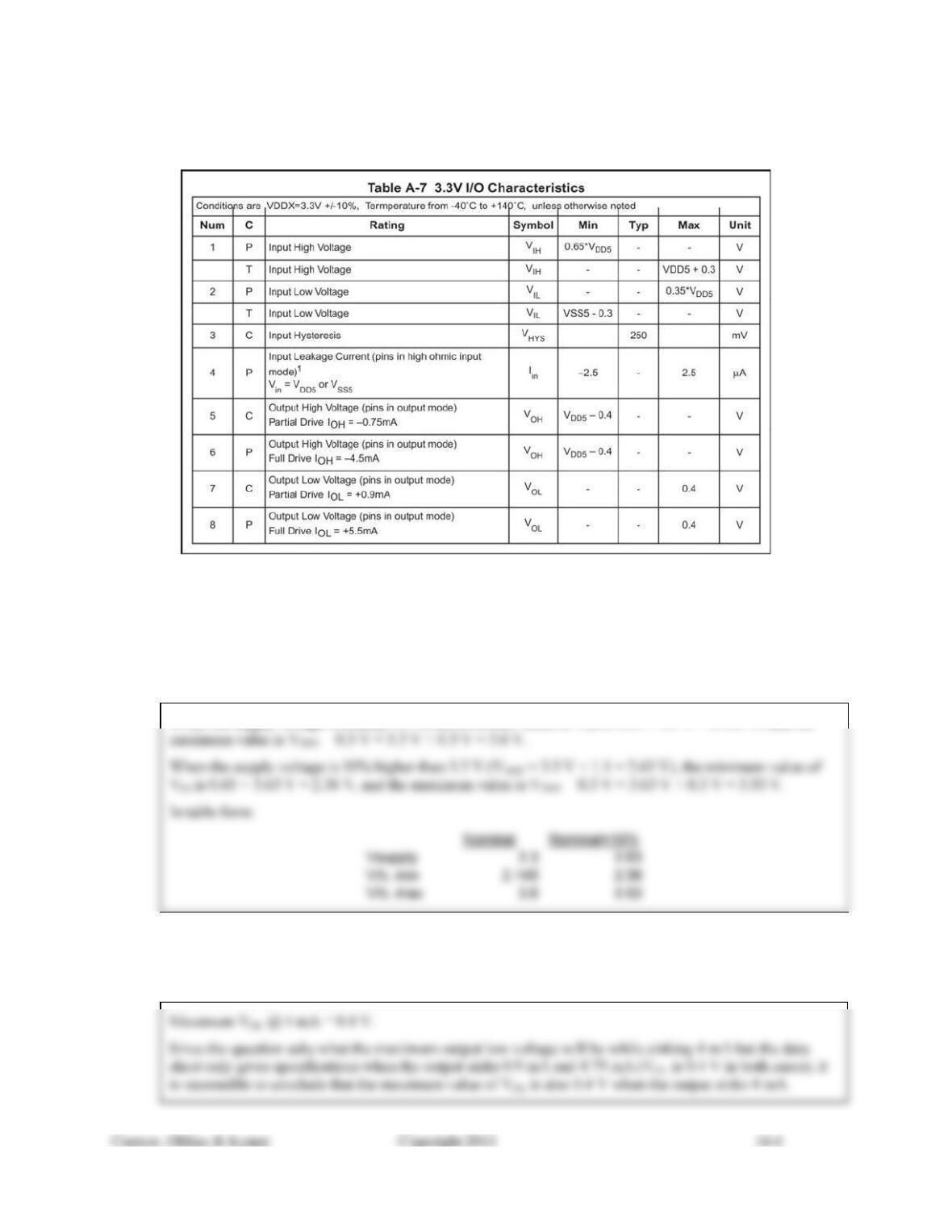
Figure 16.21: 3.3V I/O Characteristics for the Freescale MC9S12C32.
(Copyright of Freescale Semiconductor, Inc. 2010. Used by Permission)
16.1) If an MC9S12C32 is operated on a nominal 3.3 V supply that is 10% higher than the nominal value, how
would that affect the input high voltage requirement? To answer, compare the input high voltage when
operating with a supply at exactly 3.3 V to the input high voltage required when the supply voltage is 10%
higher than 3.3 V.
When the supply voltage is exactly 3.3 V, the minimum value of VIH is 0.65 × 3.3 V = 2.145 V, and the
16.2) For an MC9S12C32 operated on a nominal 3.3 V supply, what is the maximum expected output low
voltage when the output sinks 4 mA from an external source? (Use Figure 16.21 and assume full drive
strength.)
Solution Manual for Introduction to Mechatronic Design Do Not Circulate
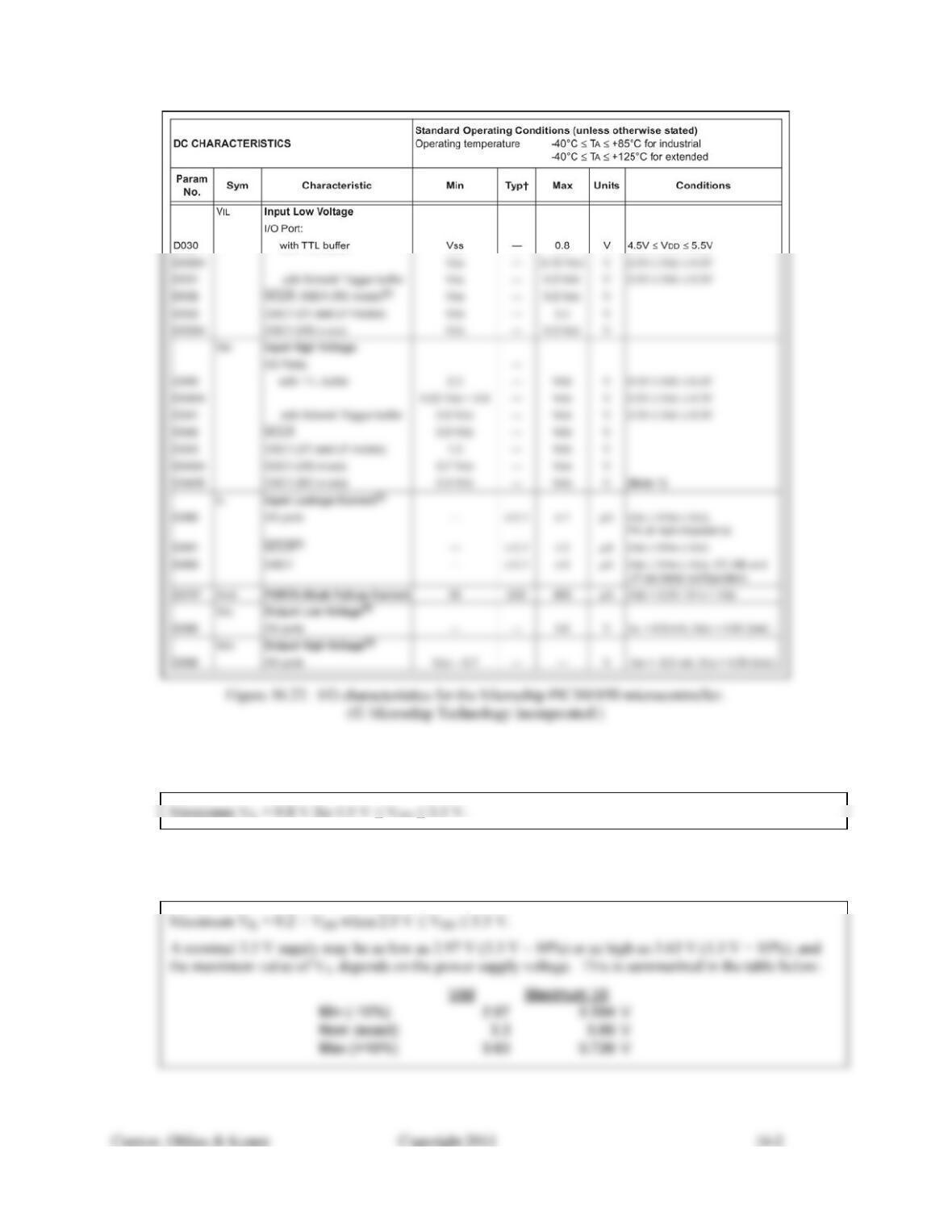
16.3) What is the maximum input low voltage for a TTL type input on the PIC16F690 when operated on a
nominal 5 V supply? (Use the specifications provided in Figure 16.22.)
16.4) What is the maximum input low voltage for a Schmitt trigger type input on the PIC16F690 when operated
on a nominal 3.3 V supply? (Use the specifications provided in Figure 16.22.)
16.5) If an output of PIC16F690 operating with a 5 V (± 10%) supply is connected to an input of an MC3479
operating with a 7.5 V supply, will the devices be operating within their specifications? Use Figure 16.22
and quote the relevant specifications to support your answer.
Yes all specifications are met. The following tables cite the relevant specifications and give the
justifications for the conclusion.
16.6) Is it possible to have a PIC16F690 operating at 3.3 V exchange data (both inputs and outputs) with an
MC9S12C32 operating at 3.3 V with both devices operating within their specifications? Use Figures 16.21
and 16.22 and quote the relevant specifications to support your answer.
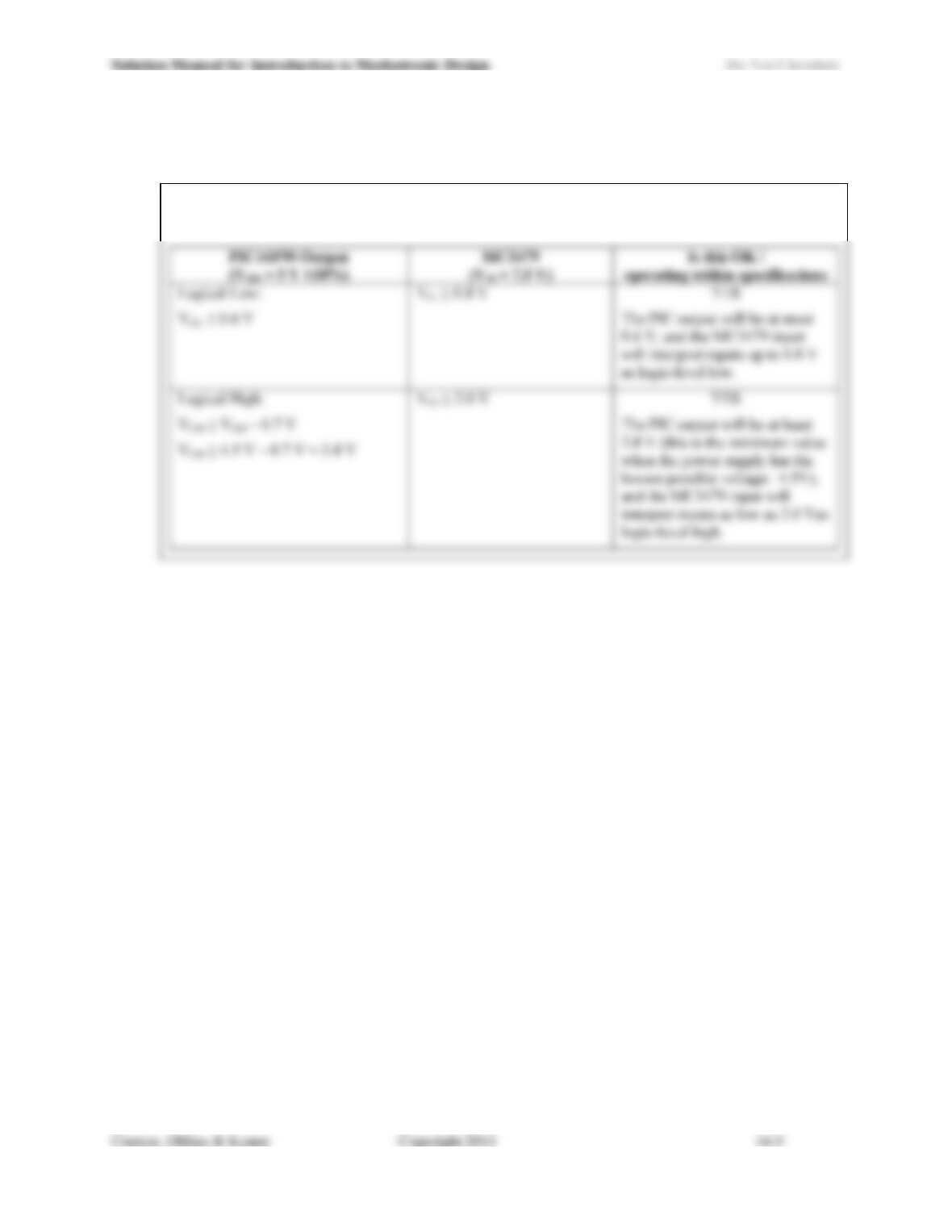
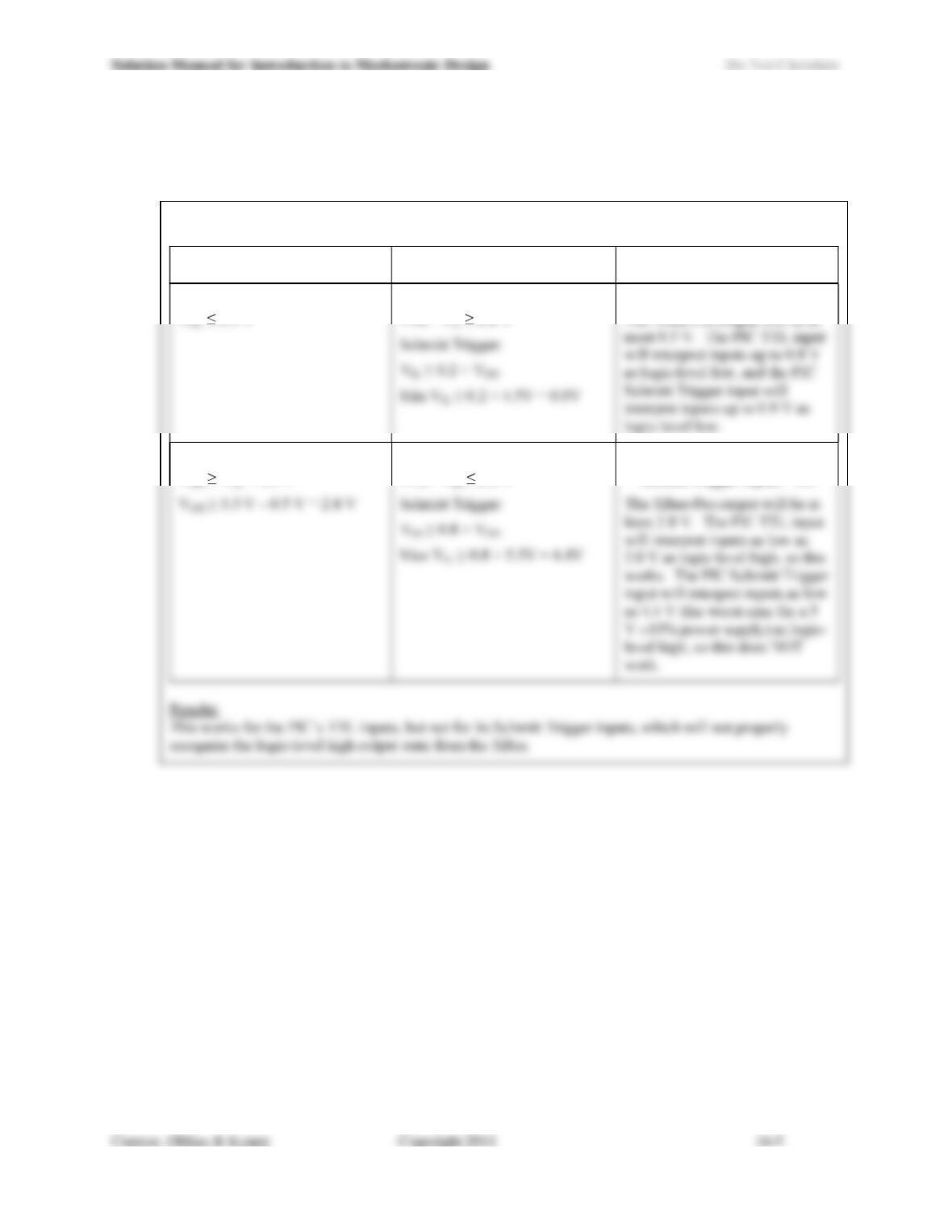
Yes this works in both directions. The following tables cite the relevant specifications and give the
justifications for the conclusion.
PIC16F90 Output
(VDD = 3.3V)
MC9S12C32 Input
(VDD5 = 3.3V) Is this OK?
Logical Low:
VOL 0.6 V
VIL 0.35 × VDD5 = 1.155V
YES
The PIC output will be at most
Logical High:
YES
MC9S12C32 Output
(VDD5 = 3.3V)
PIC16F90 Input
(VDD = 3.3V) Is this OK?
Logical Low:
YES
Logical High:
VOH VDD5 0.4 V
VIH 0.25 × VDD5 +0.8 = 1.625
YES
The MC9S12C32 output will be
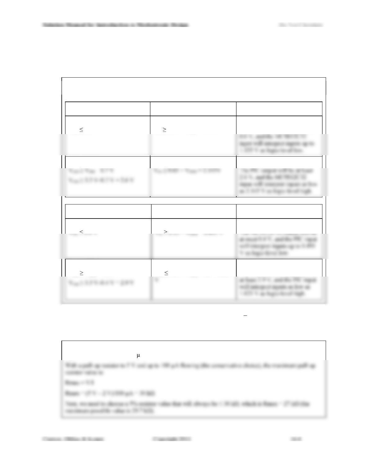
16.7) What is the maximum value for a pull-up resistor that is to be used on the /HSF input on an MC3479 that
is operated with a 5 V supply? Use the specifications given in Figure 16.14. Quote a standard 5% resistor
value and dont forget to allow for resistor tolerances.
From Figure 16.14, we see that VIH = 2 V (called the Threshold Voltage (Low-to-High)) and that the
input current at 5.5 V = +100 A.
16.8) Which of the inputs of a PIC16F690 (operated at 5 V ± 10%) can an output from an XBee-Pro module
(operated at 3.3 V) properly drive? (Use the specifications given in Figure 16.18 and 16.22.) If only a
subset of the inputs is compatible with the XBee-Pro outputs, identify which inputs. Quote specifications to
support your answer.
Comparing the XBee-Pros outputs to the PIC16F690s inputs:
XBee-Pro Output
(VCC = 3.3 V)
PIC16F90 Input
(VDD = 5 V ± 10%) Is this OK?
Logical Low:
VOL 0.5 V
TTL: VIL 0.8 V
YES
Logical High:
VOH VCC 0.5 V
TTL: VIH 2.0 V
TTL Inputs: YES
Schmitt Trigger Inputs: NO
16.9) Design a circuit using only passive components that will allow an output from a PIC16F690 operated at 5
V (± 10%) to properly drive the inputs of an XBee-Pro module operated at 3.3 V. You may assume that
the absolute maximum input high voltage for the XBee-Pro module is Vcc + 0.4 V. Use the specifications
given in Figures 16.18 and 16.22.
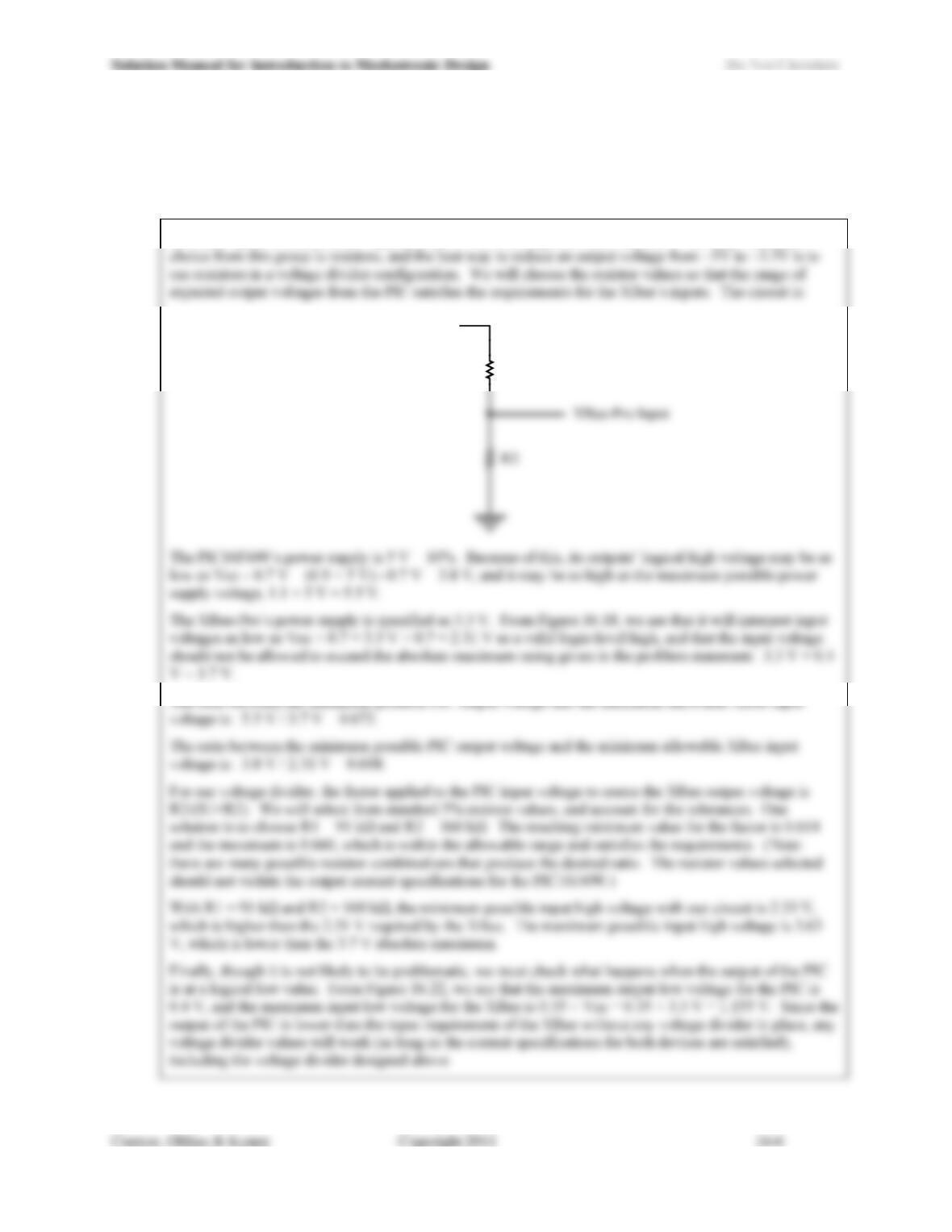
The term passive components applies only to resistors, capacitor and inductors. The only reasonable
R1
P
IC16F690 Outpu
t
16.10) Can an output from an XBee-Pro module powered by a 3.3 V supply (Figure 16.18) properly drive an input
of a MC9S12C32 powered at 5 V ± 10% (Figure 16.1)? Quote specifications to support your answer.
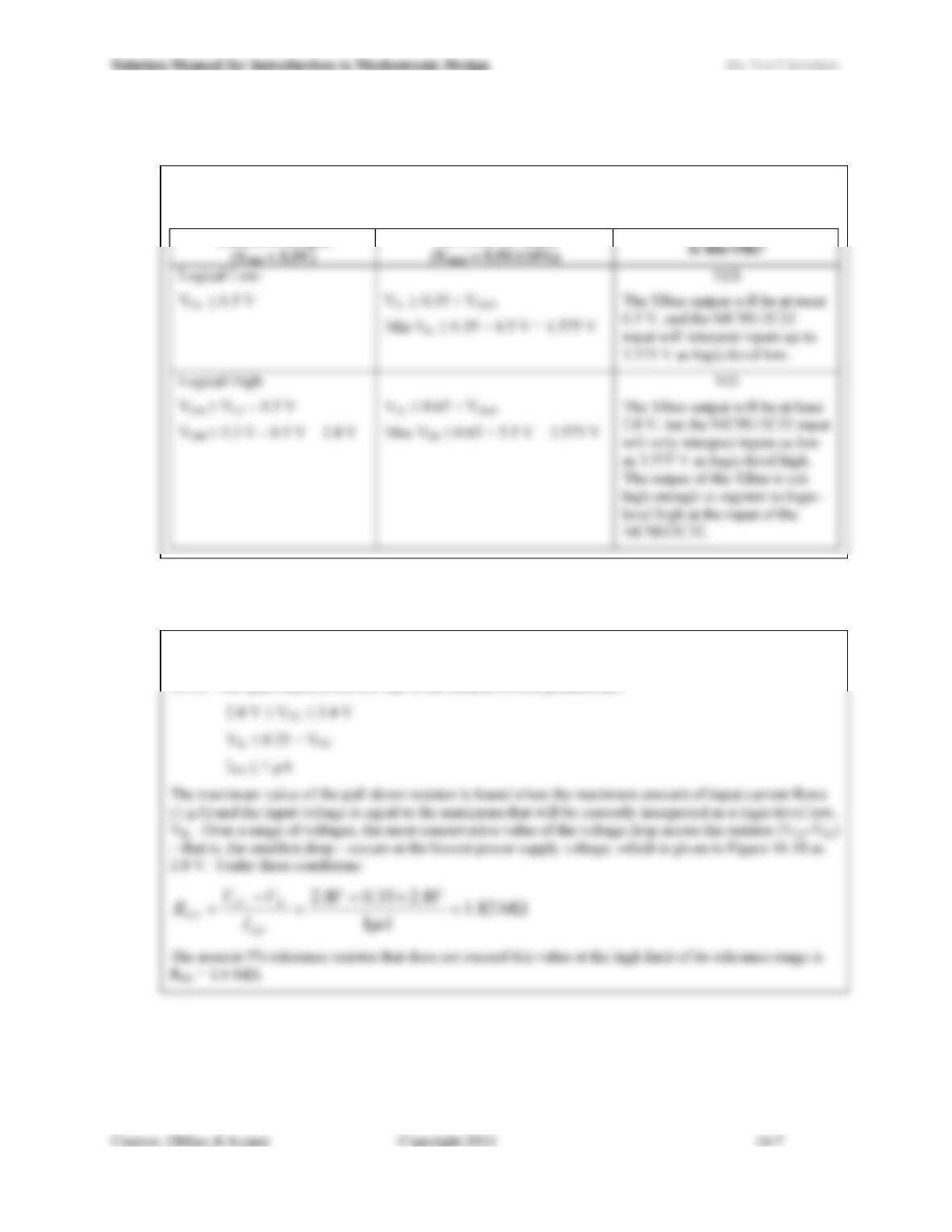
No, this will not work. The following table examines the component specifications and identifies the
problem:
XBee-Pro Output
MC9S12C32 Input
16.11) What is the maximum value for a pull-down resistor to be used on an input to an XBee-Pro module? Use
Figure 16.18 and quote specifications to support your answer.
To answer this problem, we need to know the supply voltage for the XBee-Pro. None is given in the
problem statement, so we will use the range of voltages for which the specifications are given in Figure
16.18. The specifications we will use in the solution of this problem are:
Solution Manual for Introduction to Mechatronic Design Do Not Circulate
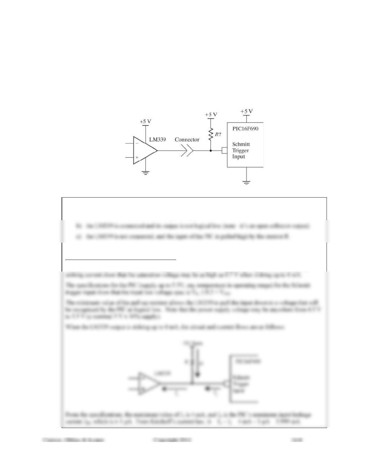
16.12) Given the circuit in Figure 16.23, what is the range of acceptable values for the resistor R? Consider that
the connector may be disconnected, and under those conditions, the input to the PIC16F690 should be a
valid logic-level high. The power supplies are nominal 5 V ± 10% supplies (remember to consider the full
range of output voltages possible from the full range of power supply voltages when determining the upper
& lower limits for the resistor). Report the largest and smallest standard 5% resistor value that will result
in all devices operating within their specifications. Use the specifications for the PIC16F690 provided in
Figure 16.22. Locate the data sheet for the LM339 on the Internet. Quote the specifications you used to
determine your answers.
Figure16.23: Circuit for Problem 16.12
Three cases must be considered:
a) the LM339 is connected and its output is logical low
For CASE A (LM339 connected, output low):
The specifications for the LM339 (5V supply, any temperature in operating range) when the output is
Solution Manual for Introduction to Mechatronic Design Do Not Circulate
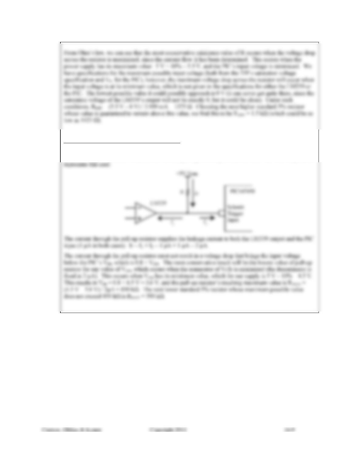
For CASE B (LM339 connected, output not low):
The LM339 has an open collector output, and does not actively pull the output voltage high. Rather, it
goes into a high impedance state, and the external pull-up resistor performs the task. The following circuit
Solution Manual for Introduction to Mechatronic Design Do Not Circulate
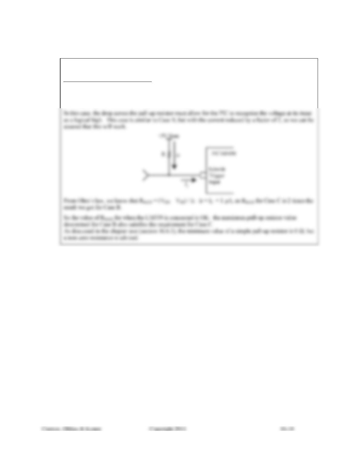
For CASE C (LM339 not connected):
Since we have already determined the maximum and minimum value for the pull-up resistor that will work
when the LM399 is connected, we need to check if this range will work when the LM339 is disconnected
and the pull-up resistor is only acting on the PICs input.