
Solution Manual for Introduction to Mechatronic Design Do Not Circulate
Chapter 15 Active and Digital Filters
15.1) How does an active filter differ from a passive filter?
15.2) Which of the named filter responses provides the best preservation of the time domain shape of a
waveform?
15.3) If the signal of interest is at 1 kHz and the interfering signal to be suppressed is at 4 kHz, what order filter
is required to achieve at least a 40 dB reduction (-40 dB gain) in the interfering signal if a) the filter type is
Bessel; b) the filter type is Butterworth?
15.4) If the filter corner frequency is 1 kHz, how much attenuation of a 4 kHz signal would you expect from a
fourth-order filter if a) the filter type was Bessel; b) the filter type was Butterworth; c) the filter type was 3
dB Chebyshev?
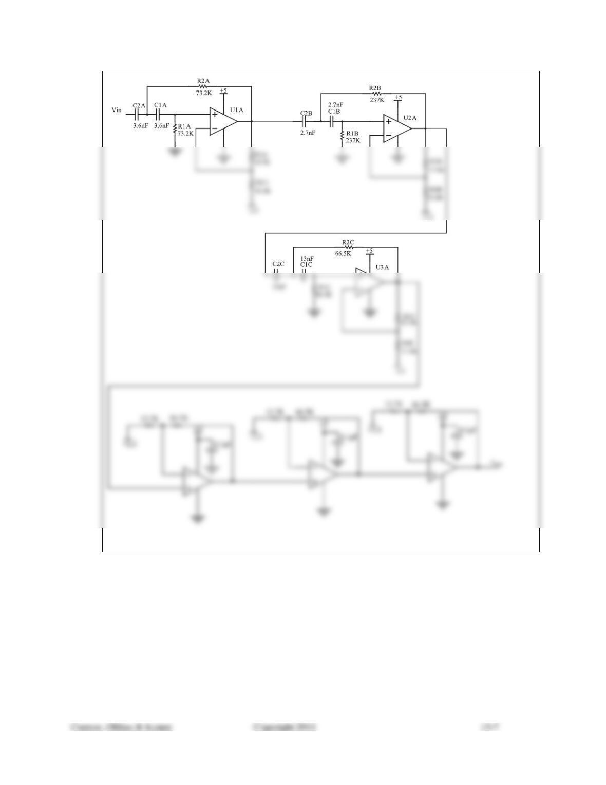
15.5) Design a sixth-order Sallen-Key filter using the simplified design procedure laid out in this chapter. Choose
from available 1% resistors.
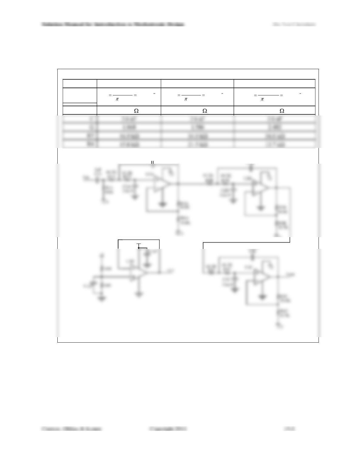
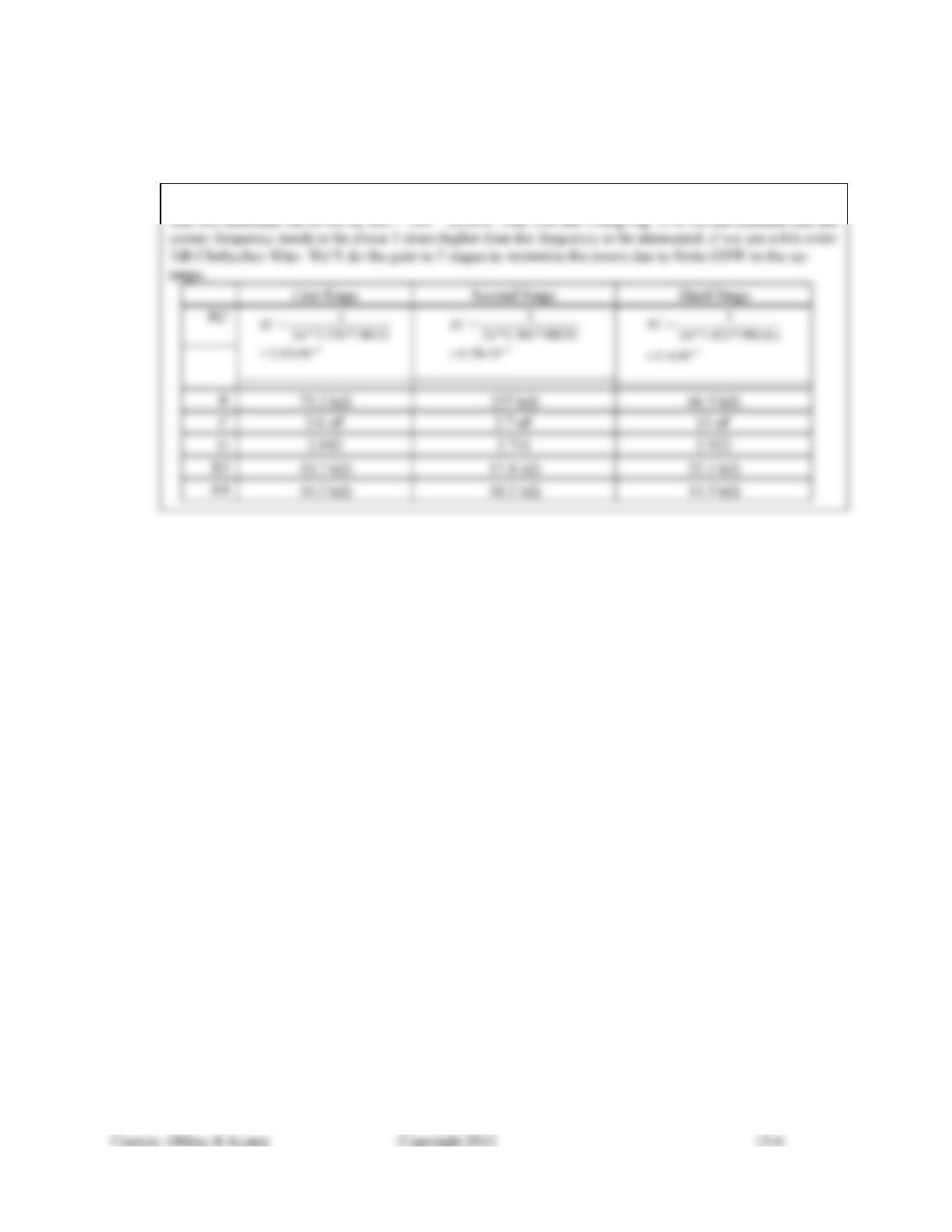
To do something different, let’s do a 1kHz low pass Butterworth filter this time:
First Stage Second Stage Third Stage
RC Product 4
1059.1
1*2
1x
kH
z
RC 4
1059.1
1*2
1x
kH
z
RC 4
1059.1
)1*2
1x
kHz
RC
R44.2 k 44.2 k 44.2 k
C1A
+2.5
+5
3.6e-9
3.6e-9
3.6e-9
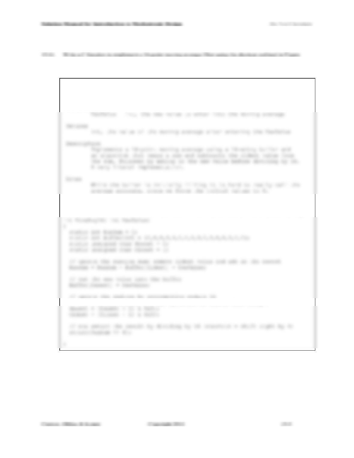
15.11. The prototype for the function should be:
int MoveAvg16Pt(int);
/****************************************************************************
Function
MoveAvg16
Parameters
Author
J. Edward Carryer, 12/19/10 15:40
****************************************************************************/
// for a binary modulo, the AND operation is faster than using %
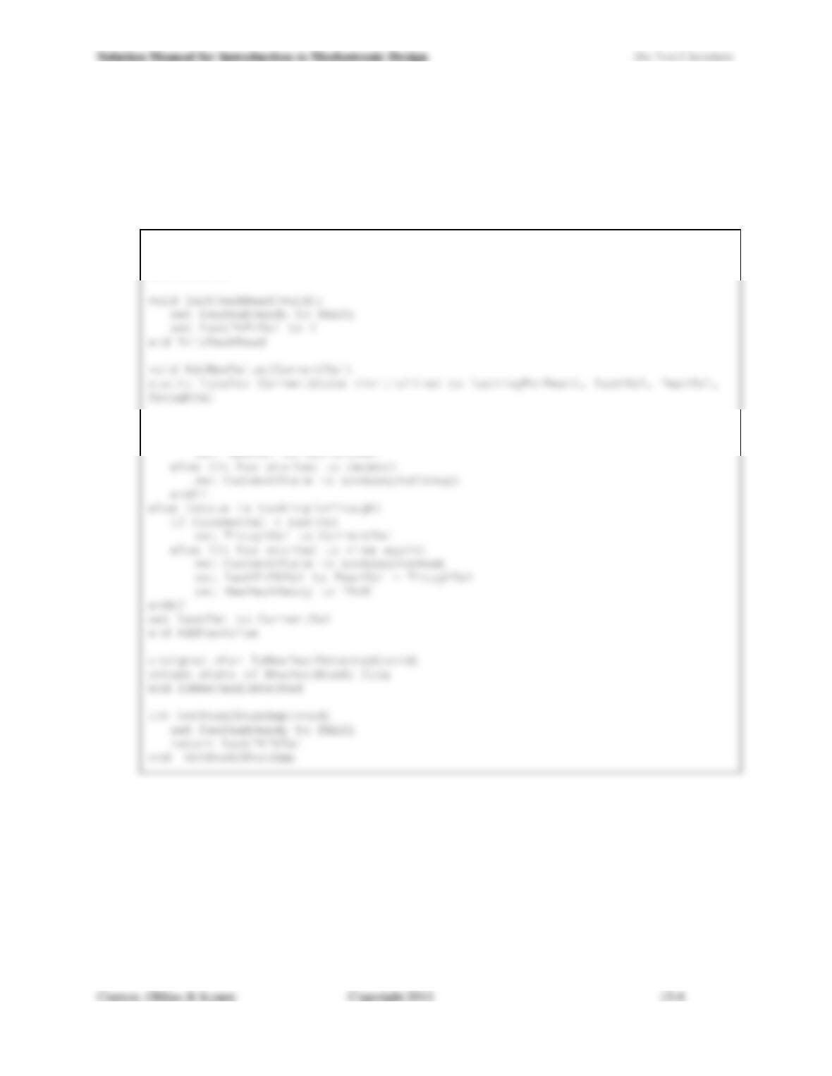
15.7) Write the pseudo-code for a four-function module to implement a peak-to-peak amplitude measurement in
software. The prototypes for the functions should be:
void InitPeakRead(void);
void AddNewValue(int);
unsigned char IsNewPeakDetected(void);
int GetPeak2PeakAmp(void);
module level variables
NewPeakReady
LastPkPkVal
if CurrentState is LookingForPeak
if CurrentVal > LastVal
15.8) Given a sinusoidal signal at 6 kHz with an amplitude of between 0 and 0.2 V superimposed on a 60 Hz
signal that varies between 0 and 1 V, design a circuit that will amplify the 6 kHz signal by a factor of
approximately 10 and attenuate the 60 Hz signal by a factor of at least 10. You should look for a design
that will use the simplest possible circuit to achieve your goals.
Solution Manual for Introduction to Mechatronic Design Do Not Circulate
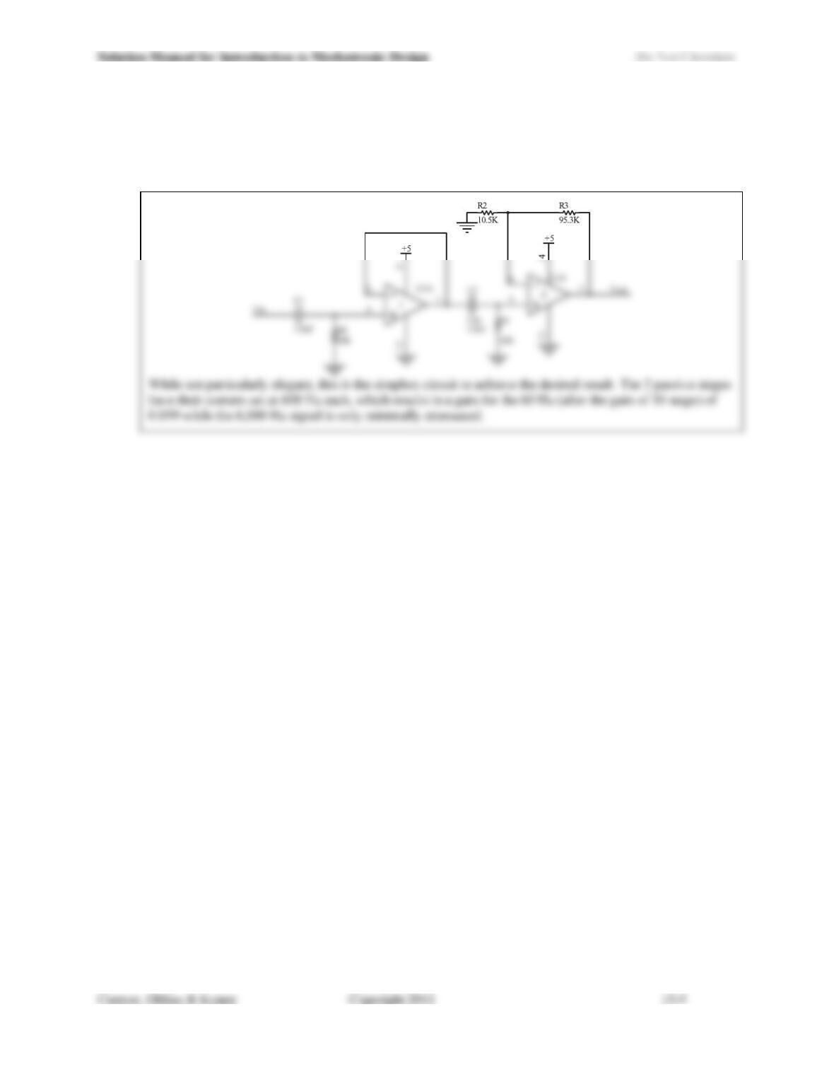
15.9) Given the same input signal as in Problem 15.8, design a circuit that will amplify the 6 kHz signal by a
factor of approximately 200 and attenuate the 60 Hz signal by a factor of at least 100.
Since we want to amplify the 6 kHz by 200 and have a net attenuation of the 60 Hz by 100, we need a filter
Solution Manual for Introduction to Mechatronic Design Do Not Circulate
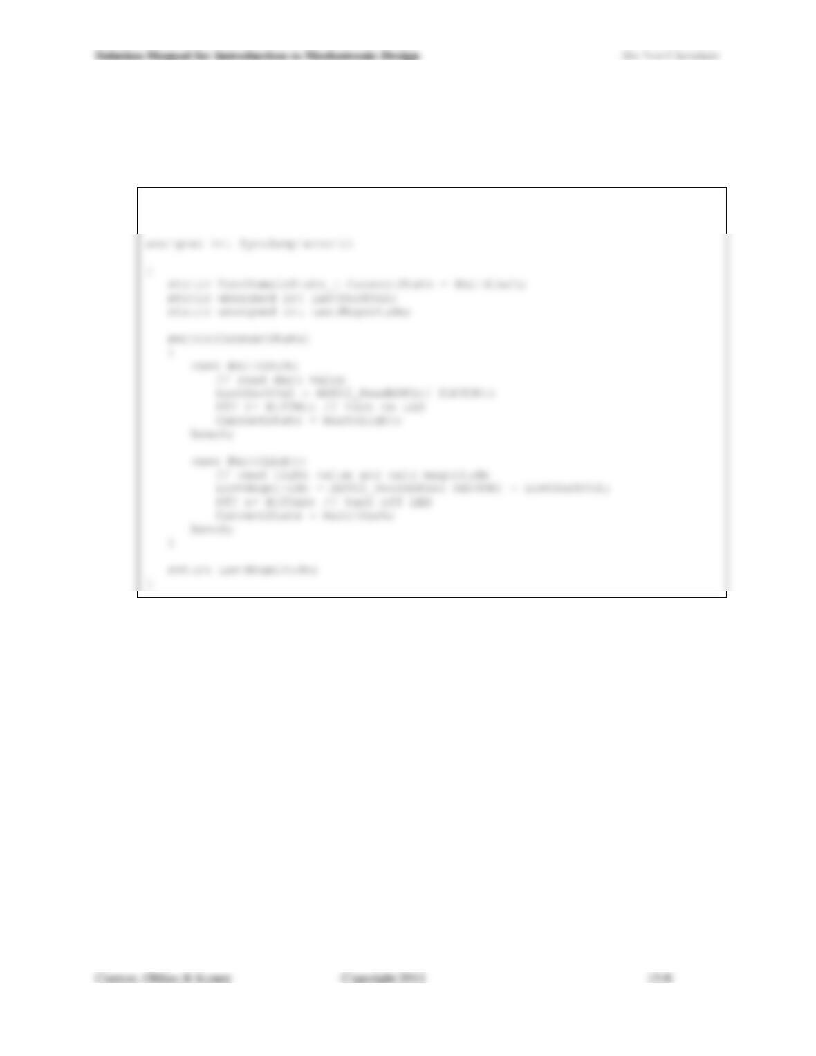
15.10) Write a C function to implement the synchronous sampling algorithm described in the last paragraph of
Section 15.2.3. The function should be nonblocking assuming that it would be called repeatedly, and on
each call step through the next phase of the sampling process. Each call should return the most recently
completed measurement.
#define SENSOR 1
typedef enum { Wait4Dark, Wait4Light } SyncSampleState_t ;