Solution Manual for Introduction to Mechatronic Design Do Not Circulate
Chapter 14 Signal Conditioning
14.1) What kind of capacitors would make a good choice for a DC blocking capacitor?
14.2) What is the minimum number of resistors that need to be changed to alter the differential gain of the circuit
of Figure 14.16 while maintaining the insensitivity to common mode voltage?
1 (see section 12.1.5.5).
14.3) You have been asked to design the signal conditioning circuit to make the signal from a new temperature
sensor suitable for use with a microcontroller. The sensor has a linear response over the range from 0 to
100 °C with a temperature coefficient of -100 /°C. At 0°C, it has a resistance of 11 k . Your circuit
should produce an output that is linearly proportional to temperature with a scale factor of 20 mV/°C over
a range from 0 to 100°C. The actual voltages that the circuit produces are up to you (i.e., the offset is not
specified), provided no device limits are exceeded and the scale factor requested is delivered. You may
assume ideal components limited only by the 5 V supply available.
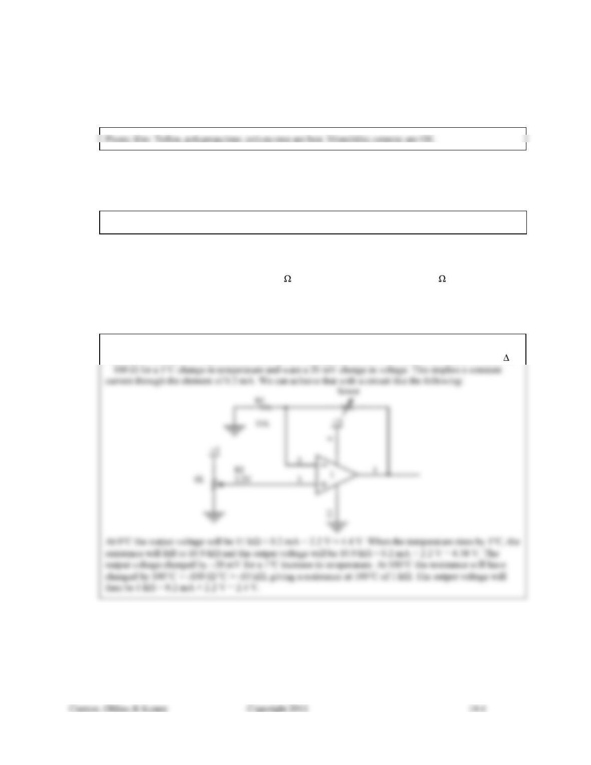
To get a linear temperature to voltage transfer through an element that has a linear temperature-to-
resistance characteristic requires a constant current through the resistive element. In this case, we have R
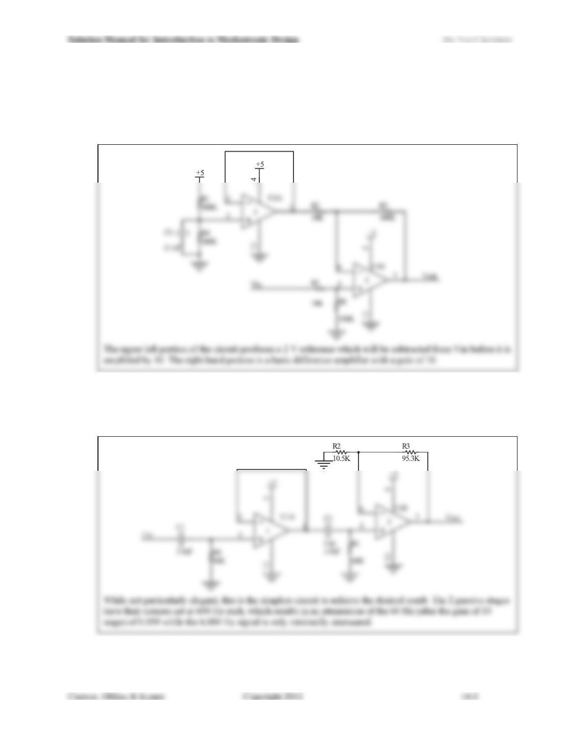
14.4) Given a slowly changing (treat it as DC) signal with an amplitude that varies between 0 and 0.2 V that is
superimposed on a 2 V true DC offset voltage, design a circuit that will amplify the slowly changing signal
by a factor of 10 while not amplifying the DC offset. The actual range of output voltage that you choose is
up to you (it may include an offset), but you must stay within the 0 and 5 V supplies that are available to
power your circuit.
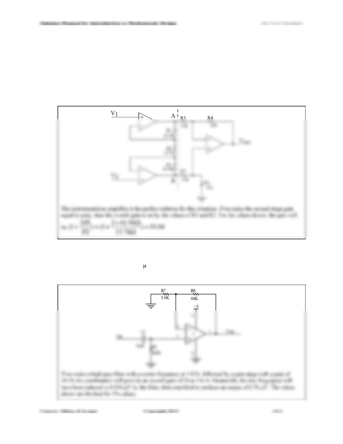
14.5) Given a sinusoidal signal at 6 kHz with an amplitude of between 0 and 0.2 V superimposed on a 60 Hz
signal that varies between 0 and 1 V, design a circuit that will amplify the 6 kHz signal by a factor of
approximately 10 and attenuate the 60 Hz signal by a factor of at least 10. You should look for a design
that will use the simplest possible circuit to achieve your goals.
14.6) Some sensors produce an output that is not a single voltage but a pair of voltages in which the actual signal
of interest is the difference between the two voltages. This is referred to as a differential output. In these
situations, it is common for there to be some DC offset that exists on both signals. For example consider
the case of an accelerometer that produces a differential output with a nominal output voltage on each of
outputs of 2.5V. The exact value of this offset is not well controlled (it may vary from device to device).
Design a circuit that will take a 0-0.2 V differential signal with frequency content from DC to 100 Hz from
such an accelerometer and amplify it by a factor of approximately 10 while minimizing the effects of the
offset voltage common to both inputs. You may assume ideal op-amps and exact value resistors are
available for your design.
14.7) Given a 200 mV peak-peak 1 kHz sinusoidal signal offset by a 200 mV peak-peak 2.7×10⁻⁴ Hz (1 cycle per
hour) signal, design a circuit to amplify the 1 kHz sinusoid by a factor of 10 while reducing the amplitude
of the low frequency signal below 1 V. Use only passive filters. You may assume ideal op-amps and
exact value resistors are available for your design. How would you modify your design if the only fixed
resistors available were 1% resistors?
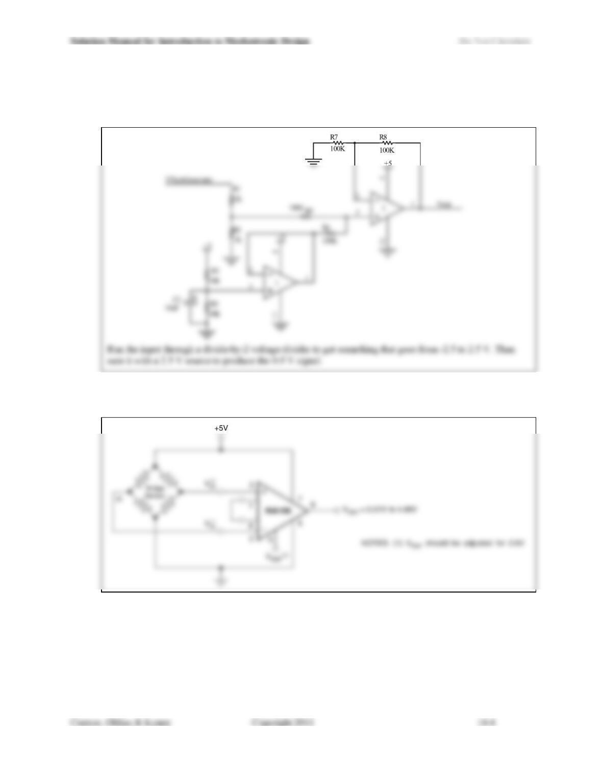
14.8) A DC motor tachometer outputs -5 to 5 V proportional to the speed and direction of the motor. Design a
circuit that takes this signal and maps it onto the range of 0-5 V so that it can be presented the input of an
analog-to-digital converter.
14.9) Show the design for a circuit using the Texas Instruments INA156 to amplify by a factor of 10 the output
of a sensor with a Wheatstone bridge sensing element powered by 5 V.
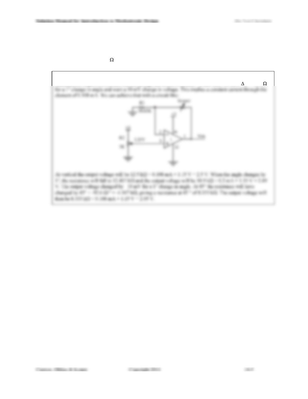
14.10) You have been asked to design the signal conditioning circuitry for an inclinometer based on a pendulum
and a potentiometer. The range of measurement should be ± 45° around vertical. The potentiometer has a
full scale resistance of 25 k and a 270° angular sweep. The potentiometer is at mid-scale when vertical
and the output of your circuit should exhibit a linear transfer function of 10 mV/°.
To get a linear angle-to-voltage transfer through an element that has a linear angle-to-resistance
characteristic requires a constant current through the resistive element. In this case, we have R = 92.6