Solution Manual for Introduction to Mechatronic Design Do Not Circulate
Chapter 13 Sensors
13.1) A microphone has a dynamic range of 88 dB and a maximum output of 2.5 V rms. What is the output
signal (in V rms) that corresponds to the minimum sound level it is capable of detecting?
13.2) From the list below, pick two sensor technologies and succinctly describe their theory of operation:
a) Geiger counter
b) Torque sensor
c) LVDT
d) pH sensor
e) Vortex flow meter
This is a go learn about it and tell us what you learned problem. Responses will vary. Check for a
13.3) For one of the sensors you chose to describe in your answer to Problem 13.2, identify a commercially
available example, locate the data sheet for the device that describes its performance, and answer the
following questions:
a) What is the range of the sensor?
b) In what form is the output (e.g., voltage, resistance, capacitance, and so on)?
c) What is the transfer function for the sensor?
d) What are the categories of error for the sensor? What is the overall accuracy?
e) Does the sensor exhibit hysteresis? If so, how much?
13.4) Using PDL (also called pseudo-code, see Chapter 6, Software Design), describe an algorithm for
performing switch debouncing in software. Does your routine report when the switch is initially activated
or when it is released?
Since this is a software design exercise, responses will vary. Evaluate answers based on plausibility and
how thoroughly the solution is thought through.
Example pseudo-code:
Routine returns with SwitchOpen, SwitchClosed, NoNewSwitch
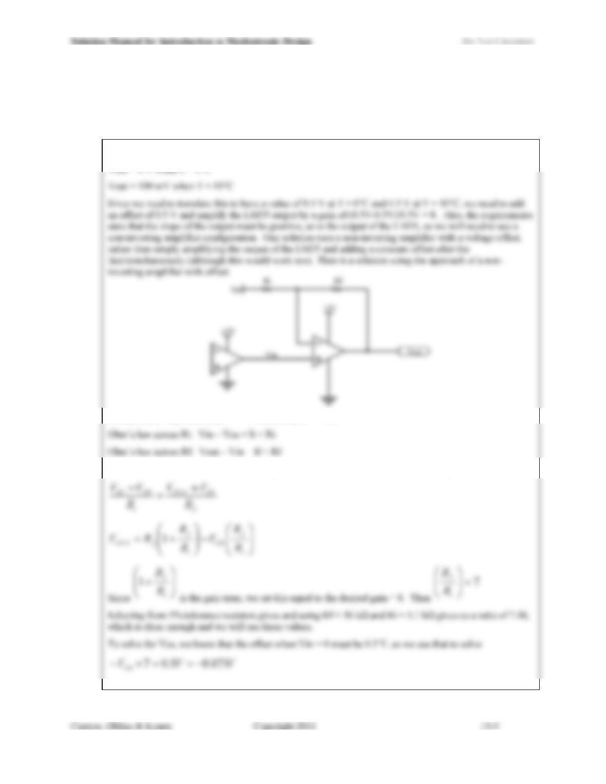
13.5) An LM35DT temperature sensor is used to monitor an environment where the temperature ranges from 0
to 50°C. Design an interface circuit that has an output ranging from 0.5 to 4.5 V that is linear with
temperature over the range to be measured. For your circuit, you may make use of ideal op-amps, but
select only standard 5% tolerance resistor values.
From the LM35 data sheet:
Golden Rule #2 gives us that V+ = Vin and thus V- = Vin
Golden Rule #1 (inputs draw no current) gives us Ii = If, so we can combine above expressions to write:
Solution Manual for Introduction to Mechatronic Design Do Not Circulate
The circuit is then fully defined as:
-0.071V
Vin
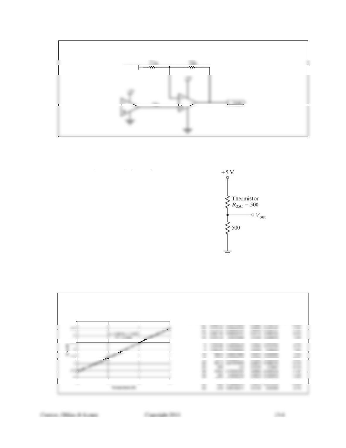
13.6) One method of creating a pseudo-linearized output from a standard NTC thermistor is called voltage mode
linearization in which the thermistor is placed in series with a standard resistor (where R1 = R25C, the
thermistors resistance at 25°C) to create a voltage divider, as shown in Figure 13.80.
Temperature (C) R (Ohms)
-25 4,240
-20 3,311
-15 2,607
-10 2,070
-5 1,656
0 1,335
5 1,083
10 885
15 727
20 601
25 500
30 418
35 352
40 298
45 253
50 216
Figure 13.80
For the thermistor characteristics shown, plot the resulting Vout. What is the maximum linearity error that
results (the difference between the best-fit straight line through the data and the data point furthest from the
line), stated both in volts and in % F.S.O.?
Maximum error is at the lowest value (-25 °C), which is -3.8%. Overall, this is a simple and effective
method for linearizing the NTC thermistors output. The following plot and table were used to determine
the performance:
4
-25 0 25 50
Temp (C) R (ohms) Vout (V) Best fit (V) Error (V) Error (%FSO)
15 727.3 2.03699177 2.0593 0.022308 0.6%
40 297.6 3.13440321 3.0993 -0.035103 -1.0%
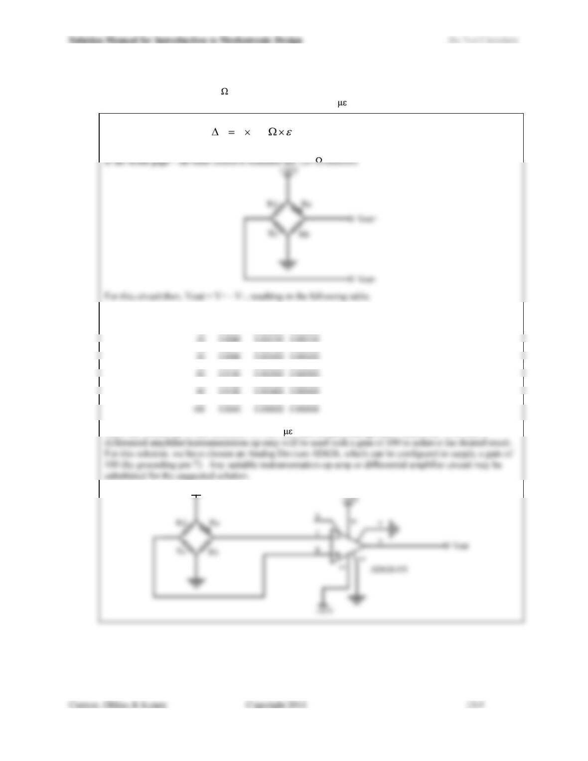
13.7) Design a strain gage interface circuit based on a Wheatstone bridge. The strain gage has a nominal
(unstrained) resistance of 120 and a gage factor of 2. The interface circuits output should be 0 V when
the gage is not subjected to strain, and sensitivity of 0.5 mV/ .
With GF = 2, we can write 1202R
From this, we can construct a Wheatstone bridge circuit and calculate the output. For the bridge shown, Ra
ue (microstrain) Delta R Bridge senso
r
Delta V
0 0.0000 5.000000 0.000000
10 0.0024 5.000050 0.000050
30 0.0072 5.000150 0.000150
50 0.0120 5.000250 0.000250
70 0.0168 5.000350 0.000350
90 0.0216 5.000450 0.000450
Since the sensitivity of this circuit is .005 mV/ , and the problem specifies sensitivity 100x this, a
+10V
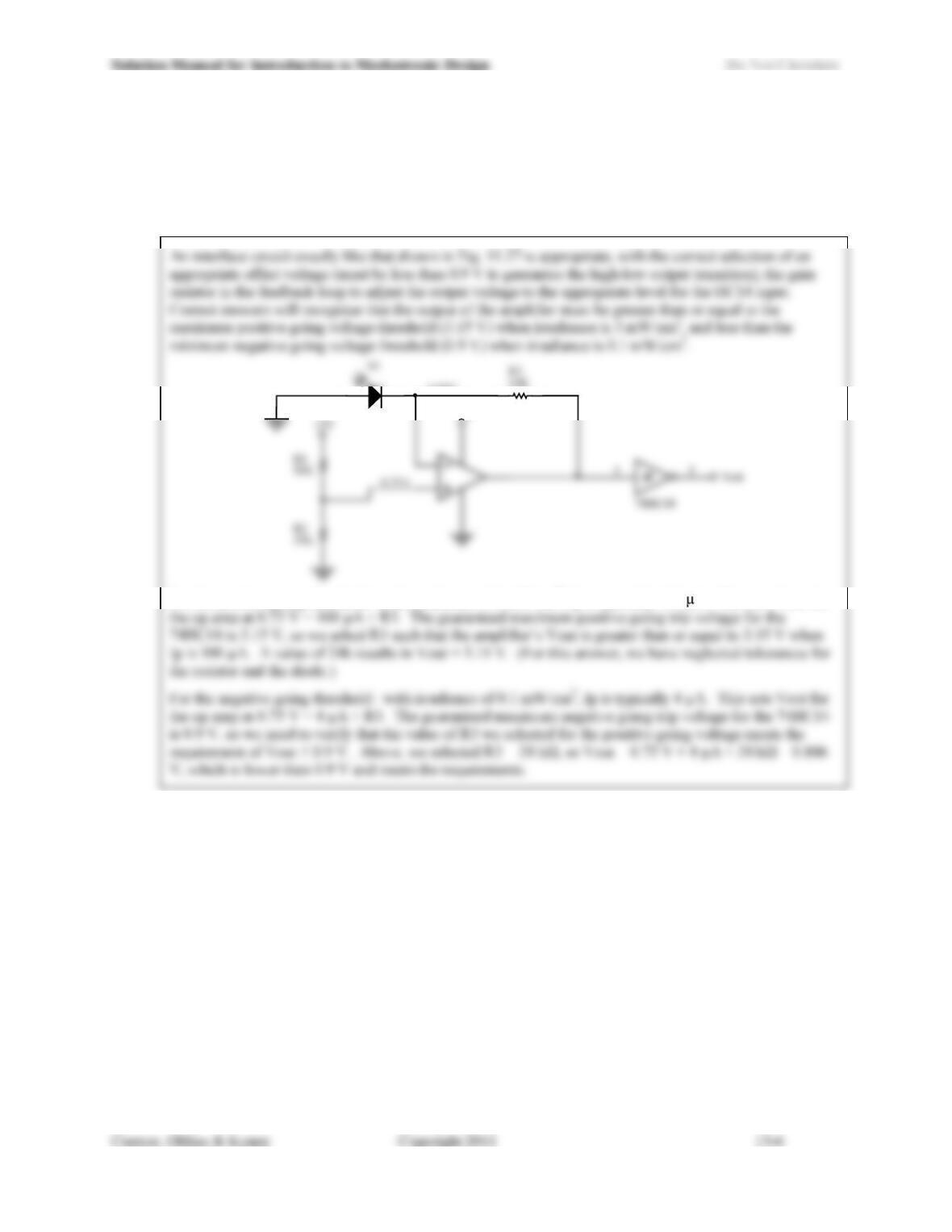
13.8) Design an interface circuit for the photo-diode whose specifications are given in Figure 13.28 that uses a
74HC14 (a logical inverter with Schmitt trigger inputs) at the output stage. The 74HC14 is to be powered
by a 4.5 V power supply and its output should be guaranteed to have made a transition from logical high to
logical low when the irradiance increases above 3 mW/cm2, and guaranteed to have made the logical low
to logical high transition when the irradiance then falls to 0.1 mW/cm2.
+5V
0.75V
For the positive going threshold: with irradiance of 3 mW/cm2, Ip is typically 100 A. This sets Vout for
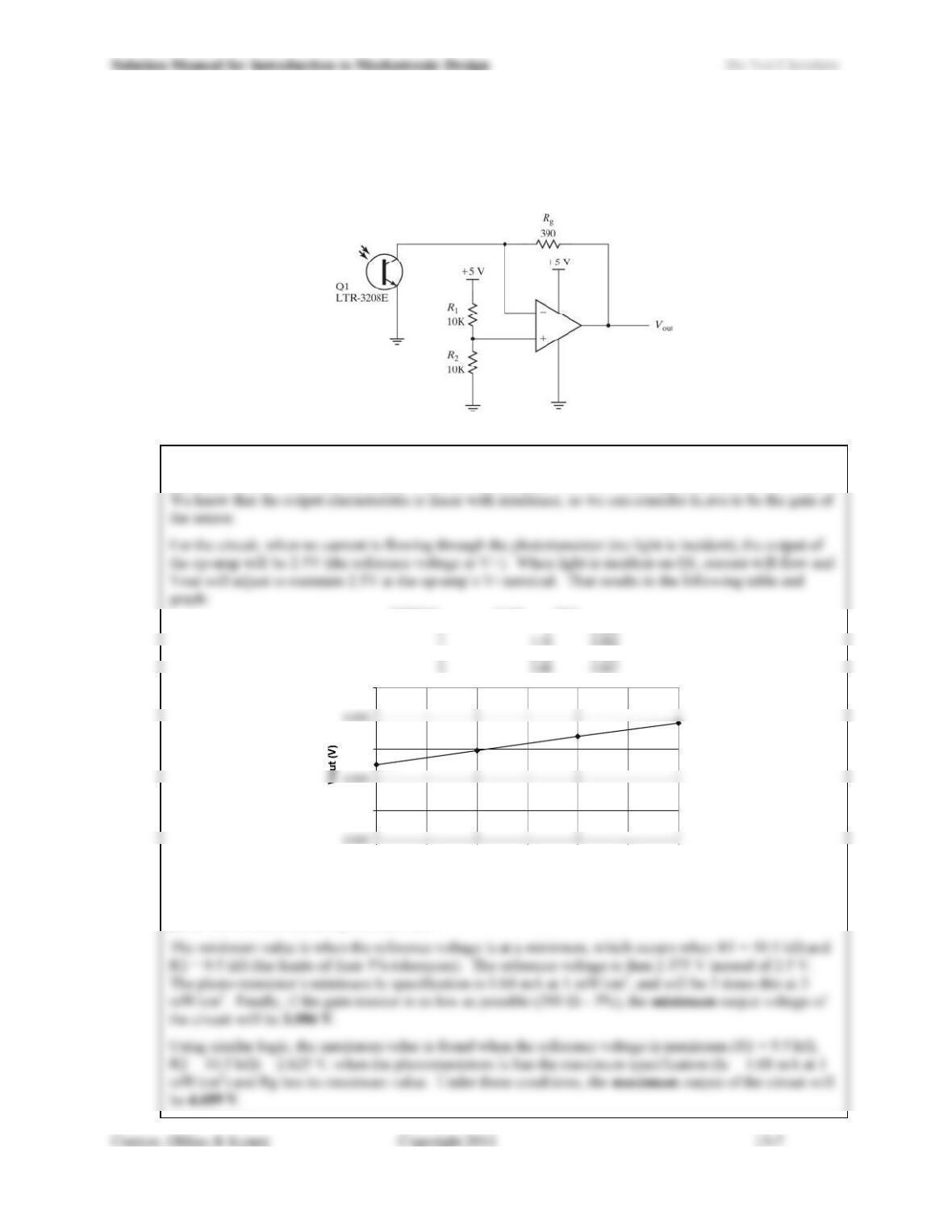
13.9) For the photo-transistor interface circuit (Figure 13.81), use the specifications given for the LTR-3208E in
Figure 13.30 to plot Vout for values of irradiance between 0 and 3 mW/cm2, assuming that the LTR-3208E
is selected from Bin A. If all resistors used in the circuit have 5% tolerance, what is the range of possible
values of Vout when the irradiance is 3 mW/cm2?
Figure 13.81
For this solution, we plot the results of a device whose Ic is the average of the maximum and minimum
specified values. From Bin A, Ic,min = 0.64 mA and Ic,max=1.68 mW when the irradiance is 1 mW/cm2.
Irradiance Ic ave Vout
0 0 2.500
2 2.32 3.405
1.000
3.000
5.000
0 0.5 1 1.5 2 2.5 3
Irradiance
For the max and min possible output values at 3 mW/cm2, we take into account the tolerances of all the
parts: the resistors and the phototransistor.
Solution Manual for Introduction to Mechatronic Design Do Not Circulate
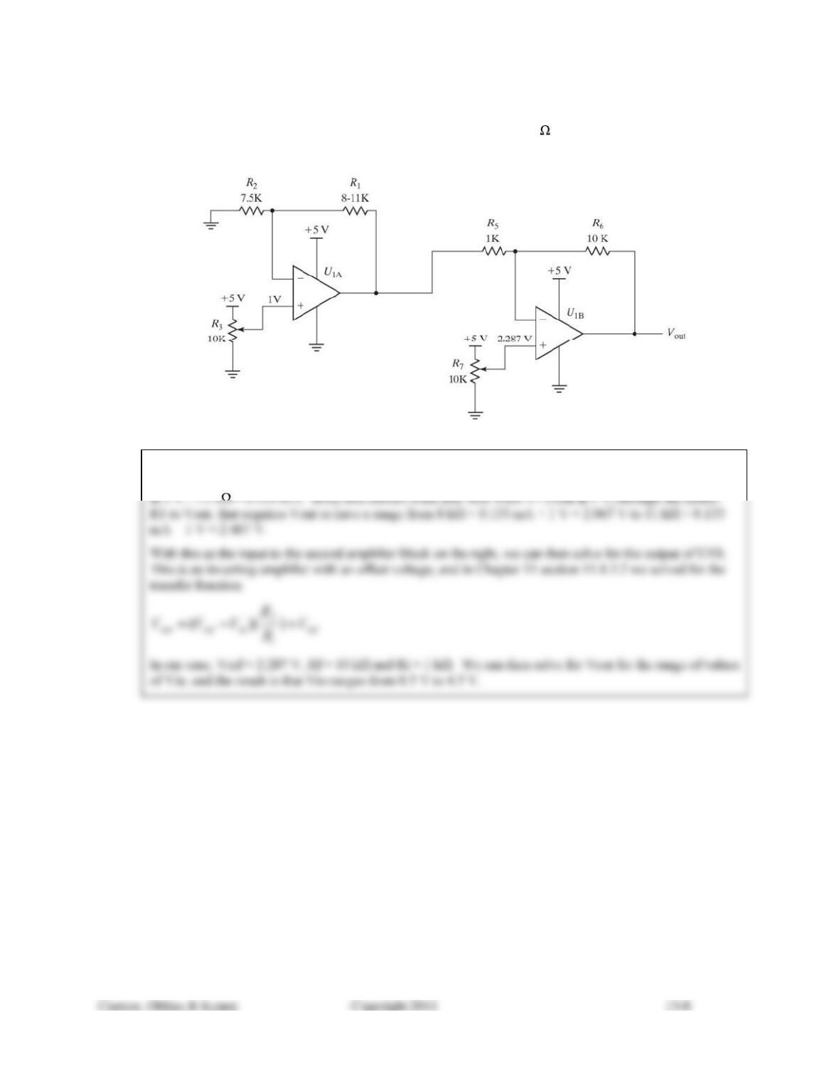
13.10) If R1 in Figure 13.82 is a sensor whose resistance varies from 8 to 11 k ,
a) what is the range of output voltages for the op-amp on the left (U1A)?
b) what are the output voltages for the op-amp on the right (U1B)?
Figure 13.82
U1A (on the left) uses a constant current configuration. Using the Golden Rules, we know that the node
between R1 and R2 is held at a constant 1 V (the same as V+), and that the current through R2 is a constant
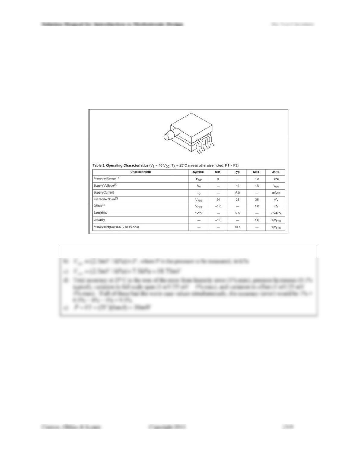
13.11) For the MPX2010 pressure sensor, use the specifications provided in Figure 13.83 to answer the following
questions:
a) What is the range of pressures you can measure with this device?
b) What is the equation for the transfer function?
c) What is the output voltage when the sensor measures 7.5 kPa?
d) What is the total accuracy of the device at 25°C without calibration (in % F.S.O., referred to here as
VFSS, or voltage at full scale span)?
e) What is the (typical) power dissipated by the device in normal operation when it is powered at 5 V?
Figure 13.83
a) 0-10 kPa