Solution Manual for Introduction to Mechatronic Design Do Not Circulate
Chapter 11 Operational Amplifiers
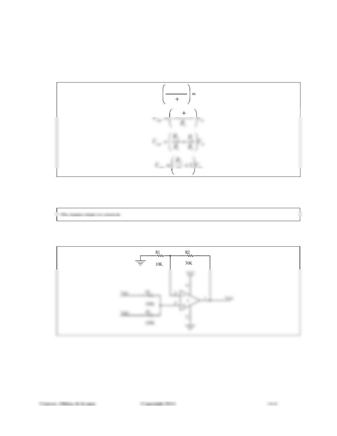
11.1) Show how you could use the voltage divider expression to develop the transfer function (input-output
relationship) for the non-inverting op-amp configuration.
in
if
i
out V
RR
R
V
if
RR
i
R
11.2) Which Golden Rule enables you to use the voltage divider expression in Problem 11.1?
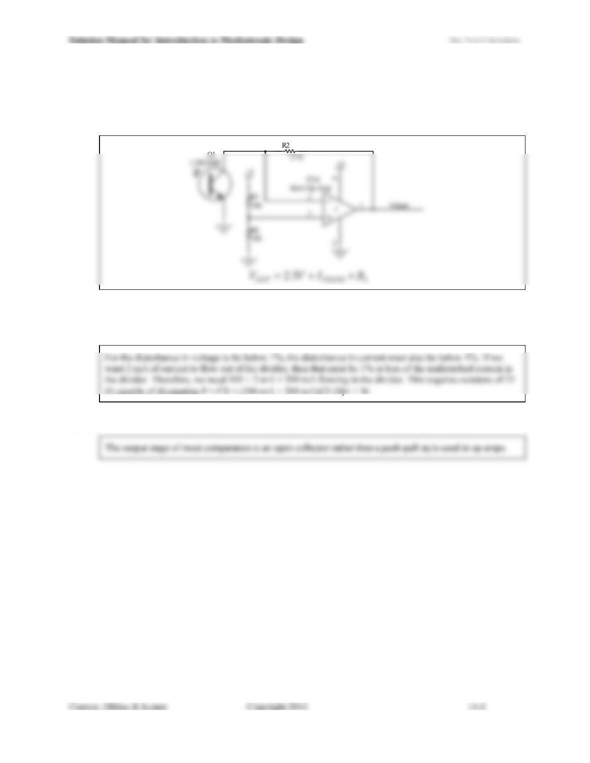
11.3) Design a circuit that will function as a non-inverting summer with a gain of 2 on the sum of the input
voltages. Assume an ideal op-amp and choose standard 5% resistors
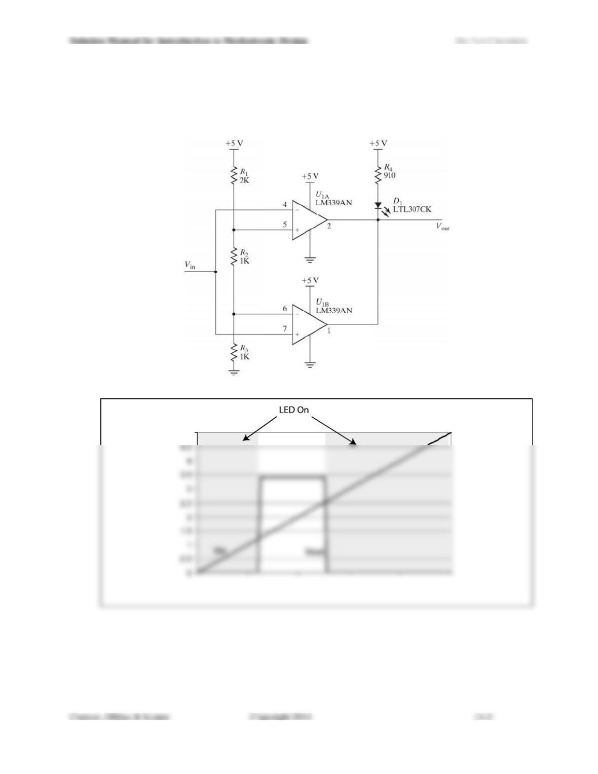
11.4) Design a trans-resistive amplifier for a photo-transistor such that the circuit will have an output of 2.5 V
with no light falling on the sensor and an output voltage that rises with increasing light levels. You have
only a +5 V supply available, but may assume an ideal op-amp. Write the gain expression relating photo-
current to output voltage for the circuit that you design.
11.5) If the voltage divider of Figure 11.9 was to produce a voltage of 2.5 V and deliver 0-2 mA into the external
circuit, what values for R1 and R2 would keep the variation in Vref below 1% of its no-load value? What
would the power rating of the resistors need to be?
11.6) Describe how the output stage of most comparators is different from the output stage of op-amps.
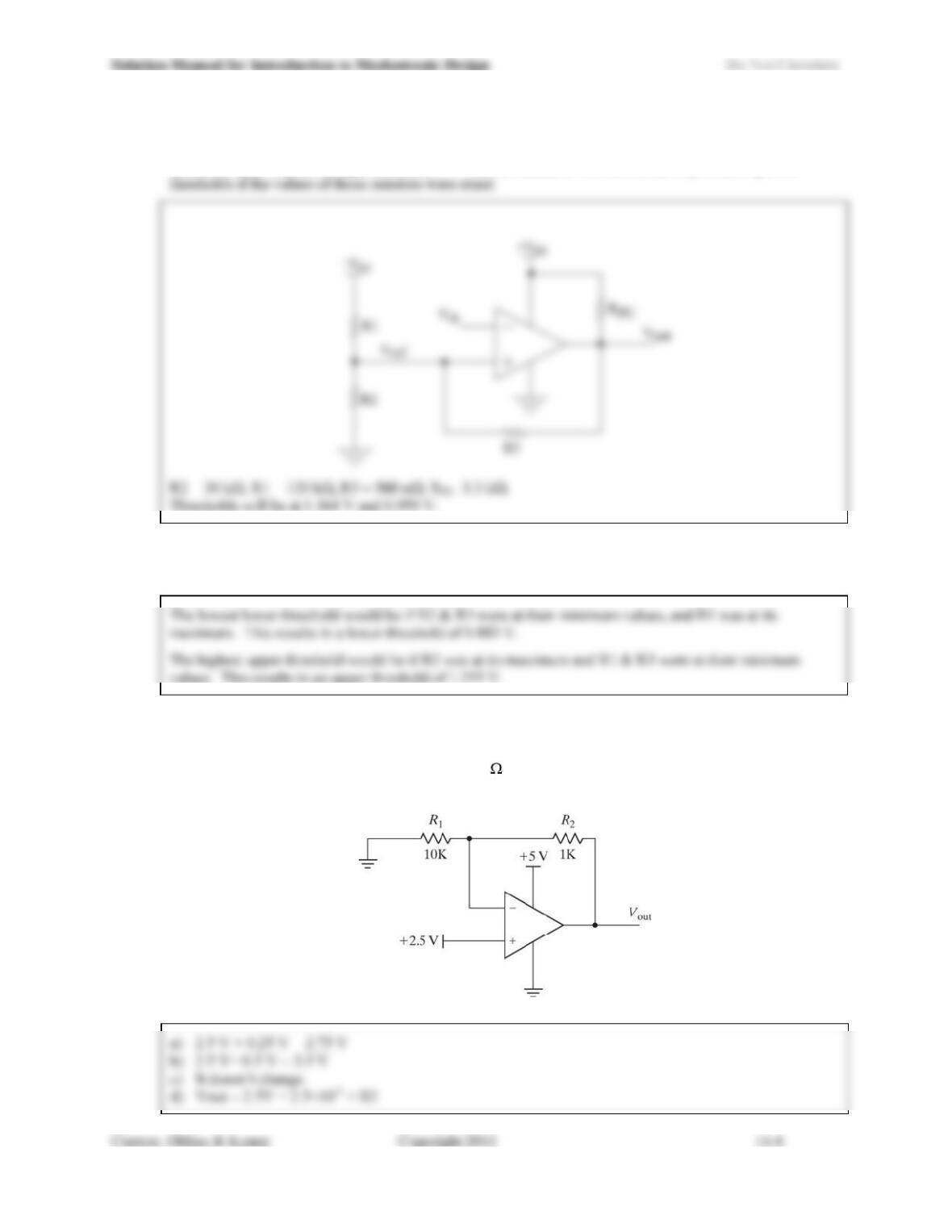
11.7) In the circuit shown in Figure 11.24, as the input voltage, Vin, is ramped from 0 V to 5 V:
a) Graph the state of the LED (D1) over the specified range of input voltages.
b) Graph the output voltage over the specified range of input voltages and include the corresponding state
of the LED.
Figure 11.24 Circuit for Problem 11.7.
5
11.8) Design a circuit to implement an inverting comparator with hysteresis having an approximately 200 mV
hysteresis band centered at approximately 1 V. Choose standard 5% resistors and report the expected
11.9) What range of thresholds (min to max) would you expect to see in the circuit of Problem 11.8 if the 5%
resistors were at the outer limits of the tolerance?
11.10) For the circuit of Figure 11.25, answer the following questions:
a) What is Vout for the circuit as drawn?
b) What would Vout be if R2 were changed to 2 k ?
c) How does the current through R1 change between the conditions of part a) and part b)?
d) Write a general expression for Vout as a function of the value of R2.
Figure 11.25 Circuit for Problem 11.10.
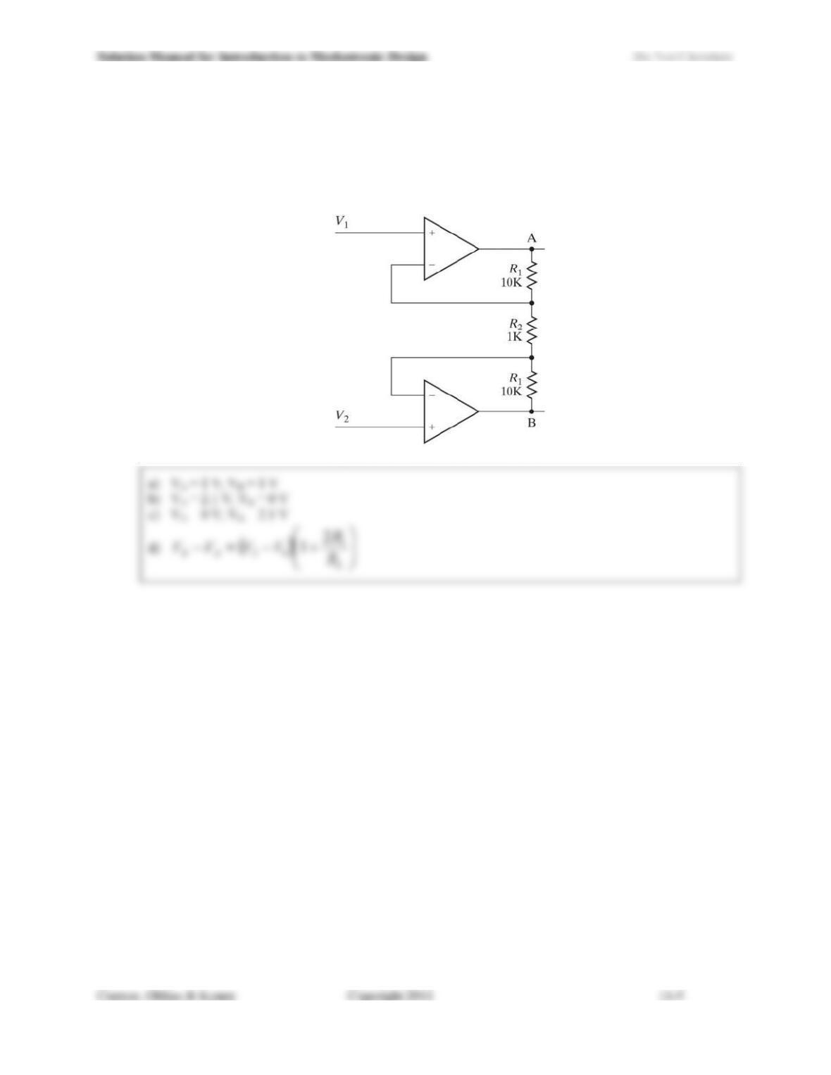
11.11) For the circuit shown in Figure 11.26, answer the following questions:
a) If V1 = V2 = 1 V, what are the voltages at points A and B?
b) If V1 = 1.1 V and V2 = 1 V, what are the voltages at points A and B?
c) If V1 = 1 V and V2 = 1.1 V, what are the voltages at points A and B?
d) Write an expression for the voltage at B minus the voltage at A in terms of V1, V2 and the values of
the resistors.
Figure 11.26 Circuit for Problem 11.11.