Chapter 5
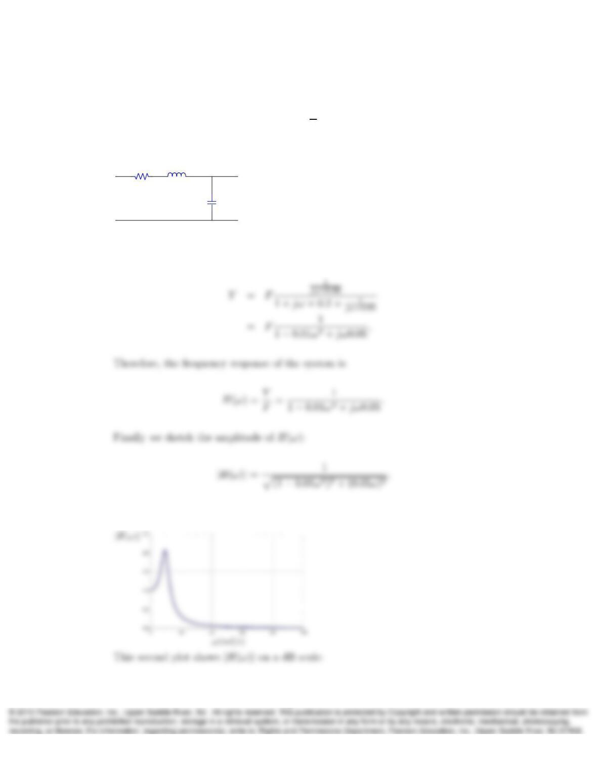
1. Determine the frequency response H(ω) = Y
Fof the circuit shown and sketch |H(ω)|
versus ω≥0. In the diagram, f(t)and y(t)denote the input and output signals
of the circuit.
+
–
+
–
0.05F
f(t)y(t)
1Ω 0.2H
Solution:
Applying voltage division using phasors:
This first plot shows |H(ω)|on a linear scale:
1
–20
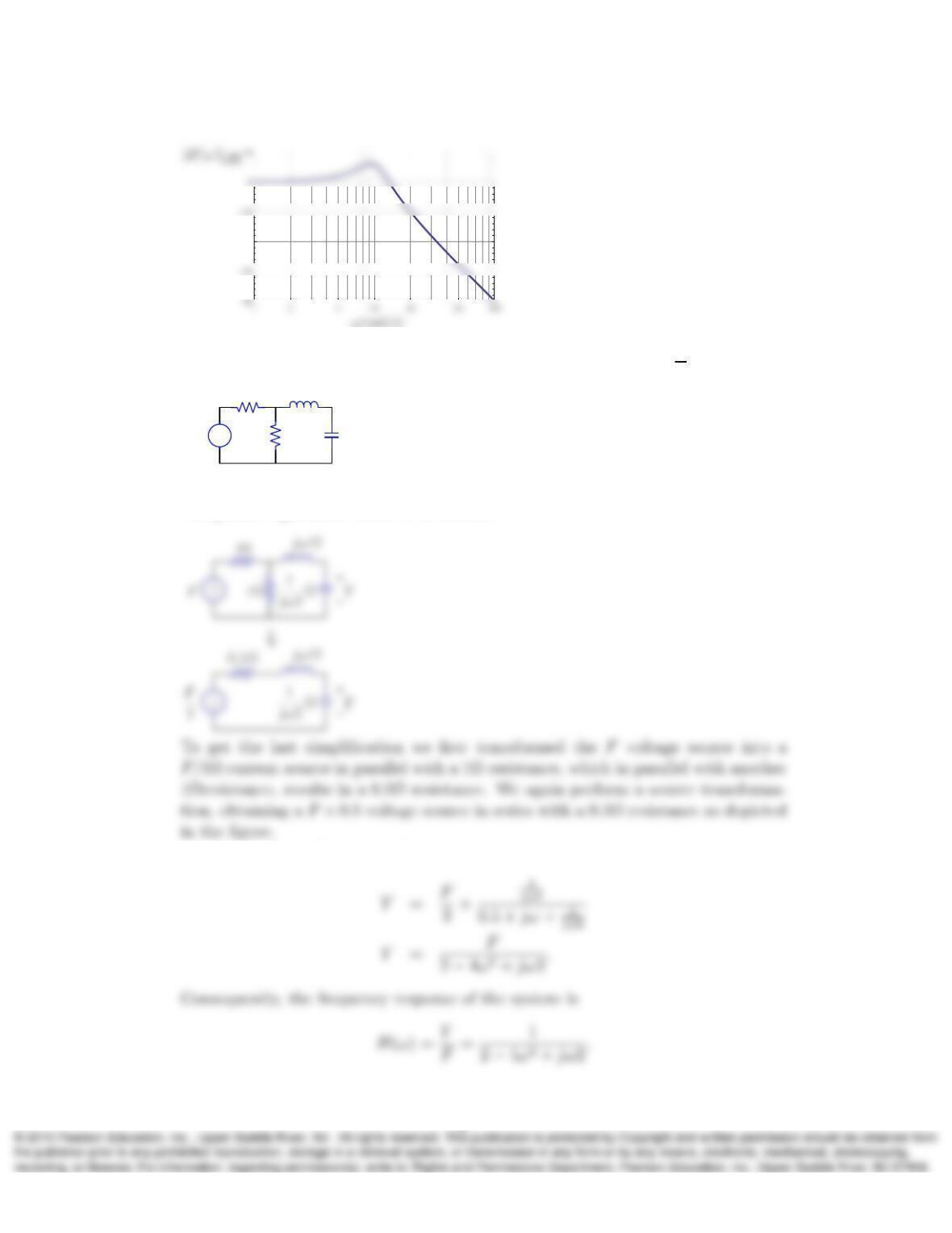
2. In the following circuit, determine the frequency responseH(ω) = Y
Fand H(0):
+
–y(t)
f(t)
1Ω 1H
2F
1Ω
+
–
Solution:
The phasor equivalent circuit is as follows:
Applying voltage division we have
2
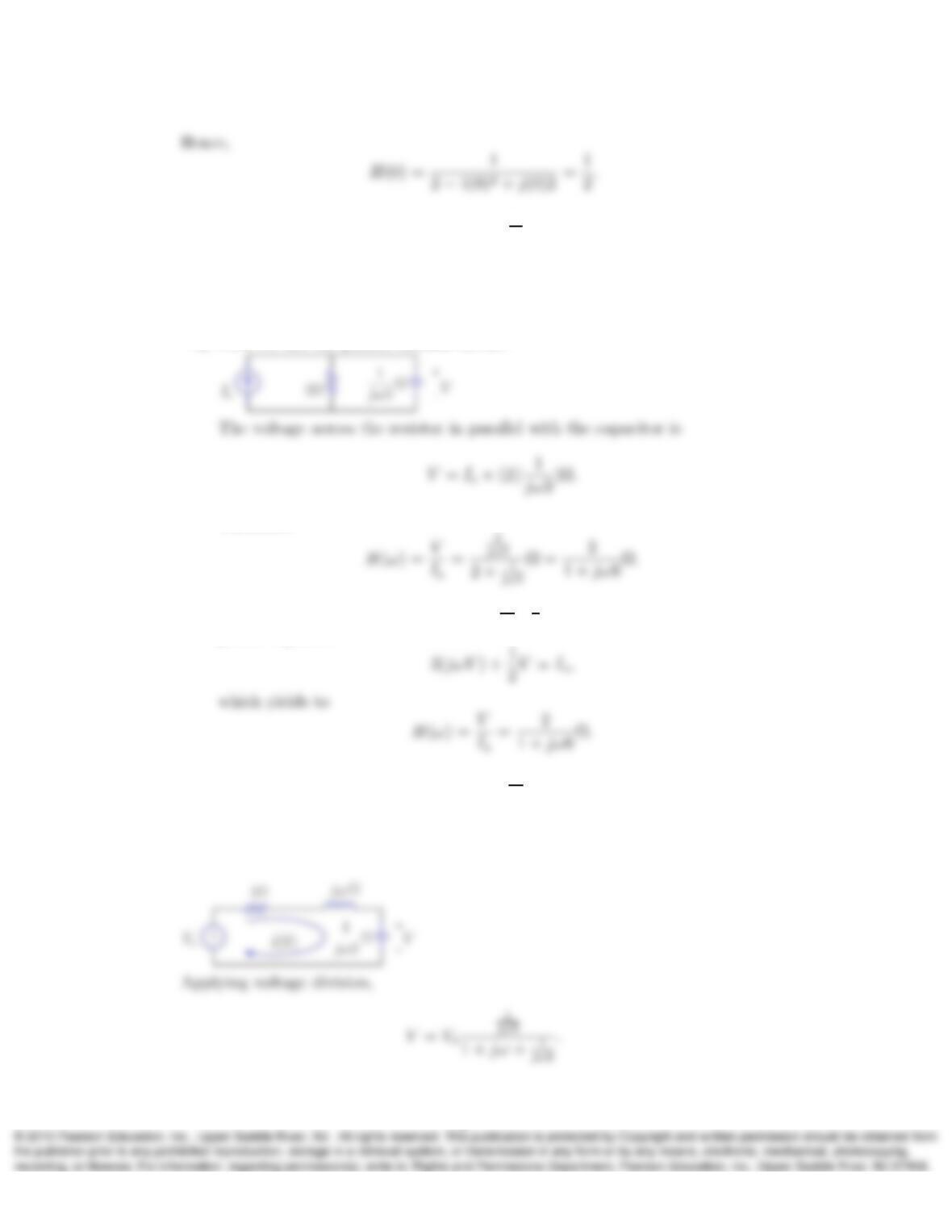
3. Determine the frequency response H(ω) = V
Isof the circuit in Exercise Problem
3.10 in Chapter 3. Note that H(ω)can be obtained with the use of the phasor
domain circuit as well as the ODE for v(t)given in Problem 3.10.
Solution:
a) First we use the phasor domain circuit:
Therefore,
b) Now starting from the ODE equation 3dv
dt +1
2v(t) = is(t), we have the following
phasor equation
4. Determine the frequency response H(ω) = V
Vsof the circuit in Exercise Problem
3.17 in Chapter 3. Sketch |H(ω)|versus ω≥0.
Solution:
First we convert the circuit into its phasor equivalent,
3
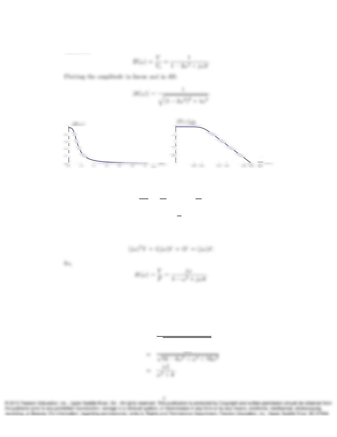
Therefore,
ω
ω
1.0
–20
0
5. A linear system with input f(t)and output y(t)is described by the ODE
d2y
dt2+ 4dy
dt + 4y(t) = df
dt .
Determine the frequency response H(ω) = Y
Fof the system.
Solution:
Equating the phasors of both sides, we have
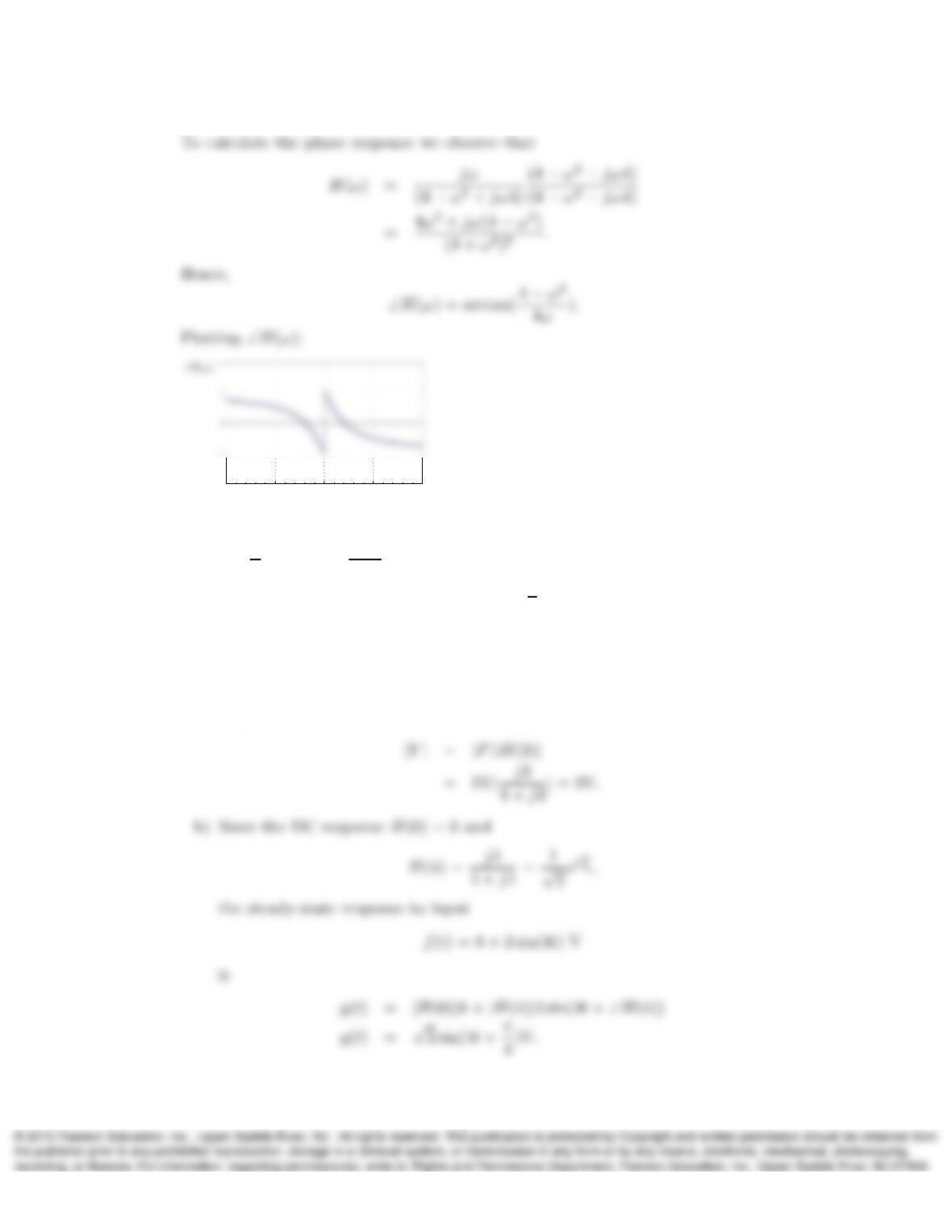
6. Determine the amplitude response |H(ω)|and phase response ∠H(ω)of the system
in Problem 5. Also plot ∠H(ω)versus ωfor −10 < ω < 10.
Solution:
Using previous result,
|H(ω)|=|ω|
p(4 −ω2)2+ (4ω)2)
ω(rad/s)
–10
–5
0
5
10
-Π
7. A linear circuit with input f(t)and output y(t)is described by the frequency
response Y
F=H(ω) = jω
4+jω . Determine:
a) Amplitude of y(t)when f(t) = 5 cos(3t+π
4)V,
b) Output y(t)when the input is f(t) = 8 + 2 sin(4t)V.
Solution:
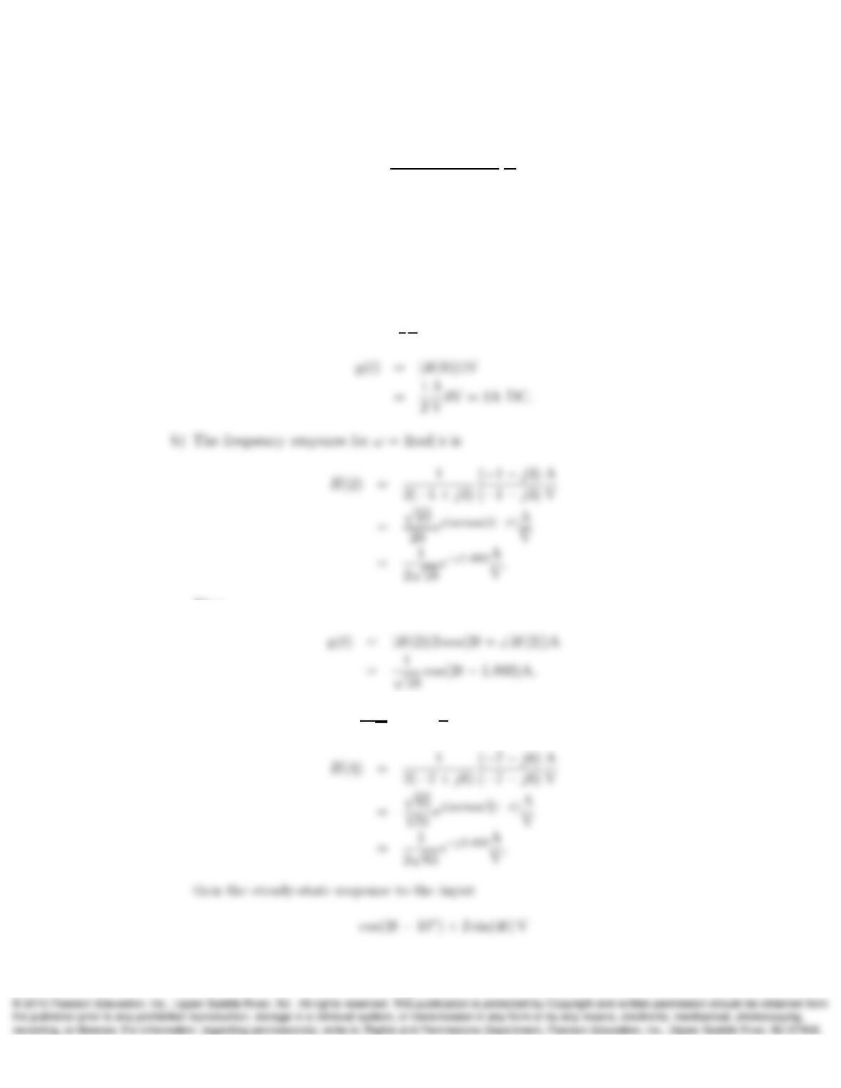
a) f(t)has a frequency of ω= 3rad/s and an amplitude |F|= 5V, same as the
amplitude of its phasor. Similarly the amplitude of y(t)is
5
8. A linear system has the frequency response
H(ω) = 1
(jω + 1)(jω + 2)
A
V.
Determine the system steady-state output y(t)with the following inputs
(a) f(t) = 4 V DC.
(b) f(t) = 2 cos(2t)V.
(c) f(t) = cos(2t−10o) + 2 sin(4t)V.
Solution:
a) Since the DC response H(0) = 1
2
A
V
Then
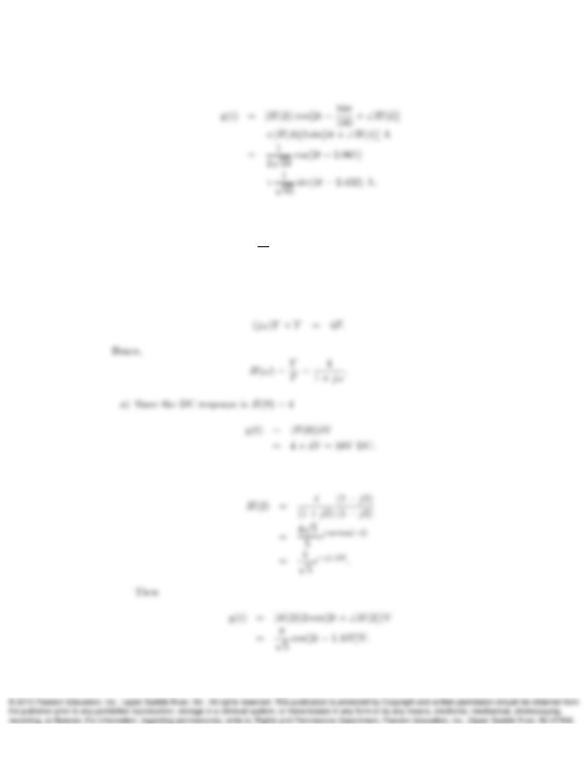
c) We have already H(2) = 1
2√10 e−j1.893 A
Vand since
6
is
9. Repeat Problem 8 for a linear system described by the ODE
dy
dt +y(t) = 4f(t).
Solution:
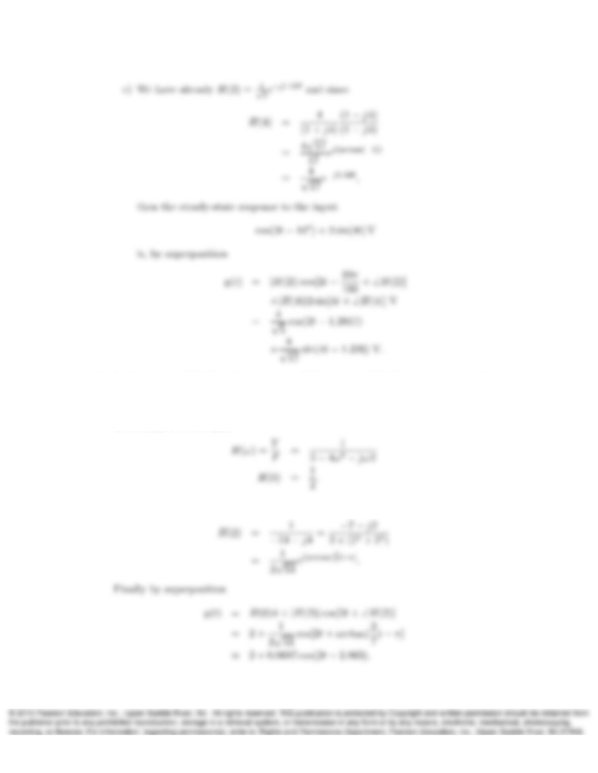
Writing the ODE equation in phasor form
b) The frequency response for ω= 2rad/s is
7
10. In the circuit of Problem 2, the input is f(t) = 4 + cos(2t). Determine the steady-
state output y(t)of the circuit.
Solution:
In Problem 2 we obtained
Now we need to obtain H(2):
8
11. Given an input f(t) = 5 + 4ej2t+ 4e−j2tand H(ω) = 1+jω
2+jω determine the steady-
state response y(t)of the system H(ω)and express it as a real valued signal. Hint:
Use the rule ejωt →LTI →H(ω)ejωt and superposition.
Solution:
Notice that
12. Repeat Problem 11 for an input f(t) = 2e−j2t+ (2 + j2)e−jt + (2 −j2)ejt + 2ej2t.
Problem:
This input can be simplified as
13. Determine whether each of the given steady-state input-output pairs is consistent
with the properties of H(ω)discussed in Section 5.2. Explain your reasoning.
a) cos(25t)→System →99.5 sin(25t−√π).
b) 2 cos(4t)→System →1 + 4 cos(4t).
9
c) 4→System → −8.
d) 4→System →j8.
e) 4→System →4 cos(3t).
f) sin(πt)→System →cos(πt) + 0.1 sin(πt).
g) sin(πt)→System →cos(πt) + 0.1 sin(2πt).
h) sin(πt)→System →sin2(πt).
Solution:
a)
99.5 sin(25t−√π) = 99.5
|{z}
cos[25t+ (−√π−π
]
10