Chapter 4
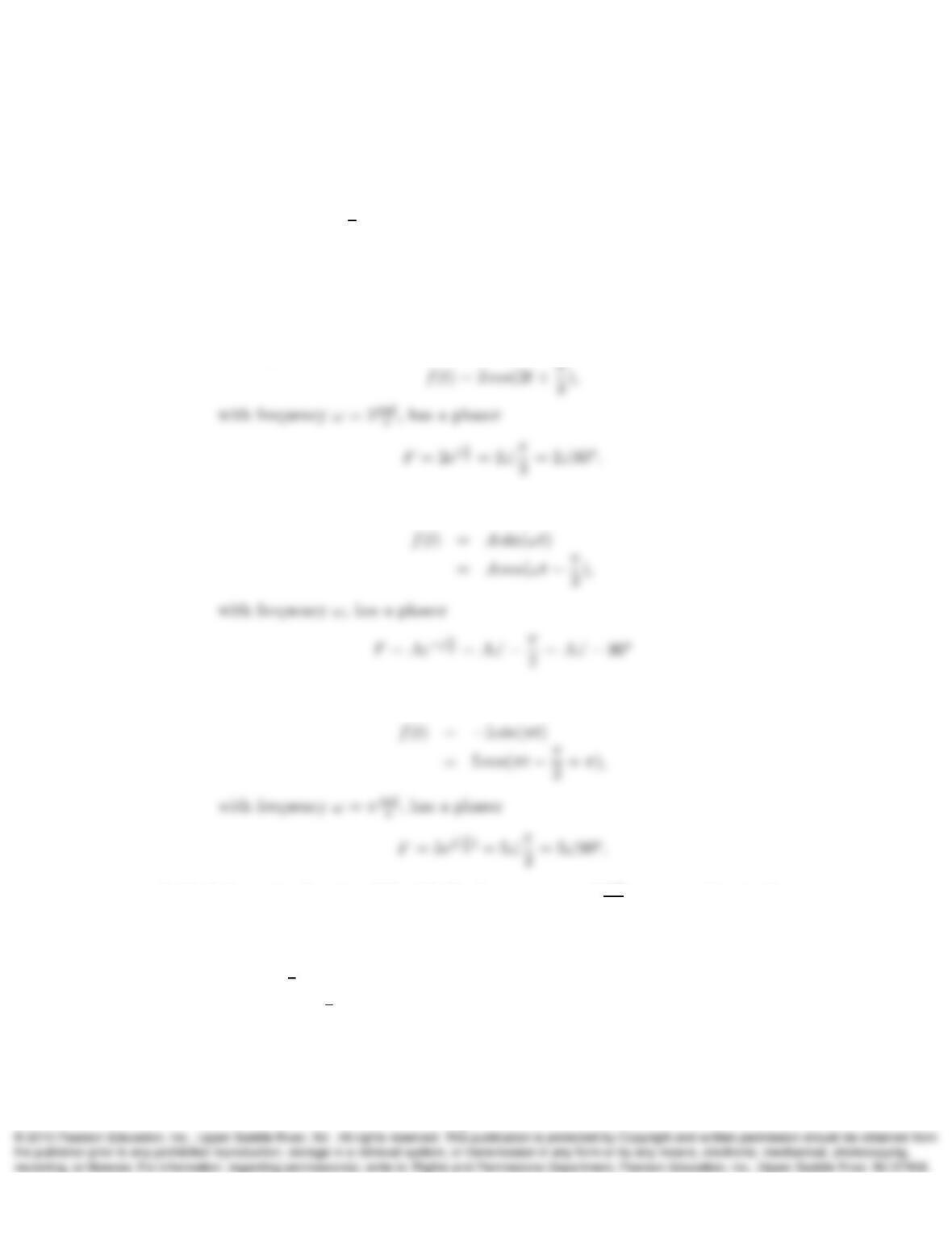
1. Determine the phasor Fof the following co-sinusoidal functions f(t):
a) f(t) = 2 cos(2t+π
3).
b) f(t) = Asin(ωt).
c) f(t) = −5 sin(πt).
Solution:
a) The signal
b) The signal
c) The signal
2. Find the cosine function f(t)with the frequency ω= 2 rad
scorresponding to the
following phasors:
a) F=j2.
b) F= 3e−jπ
6.
c) F=j2 + 3e−jπ
6.
Solution:
1
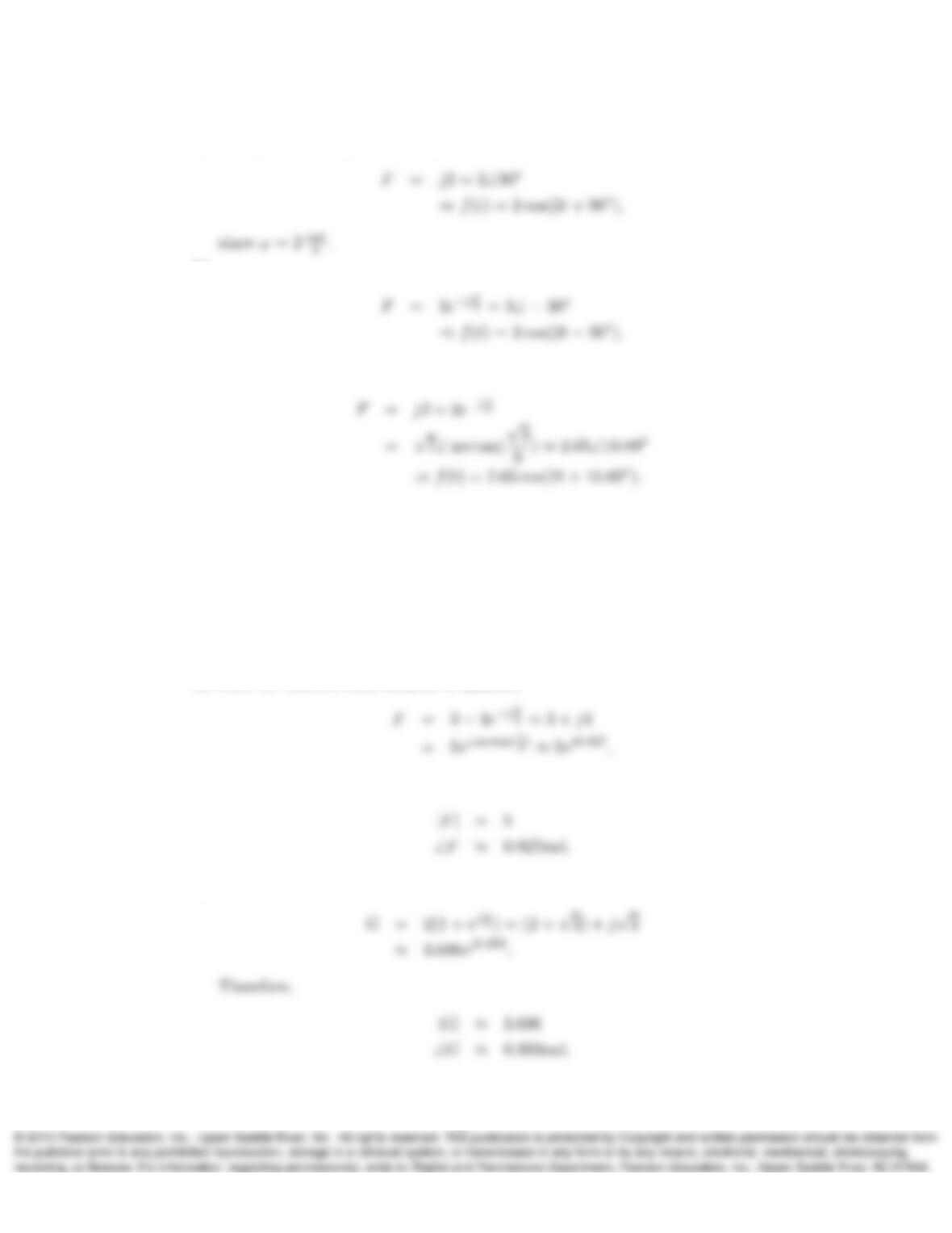
a) The phasor F=j2can be expressed as
b)
c)
3. Use the phasor method to determine the amplitude and phase shift (in rad) of the
following signals when written as cosines:
a) f(t) = 3 cos(4t)−4 sin(4t).
b) g(t) = 2(cos(ωt) + cos(ωt +π/4)).
Solution:
a) First we convert each element to phasors
Consequently
b)
2
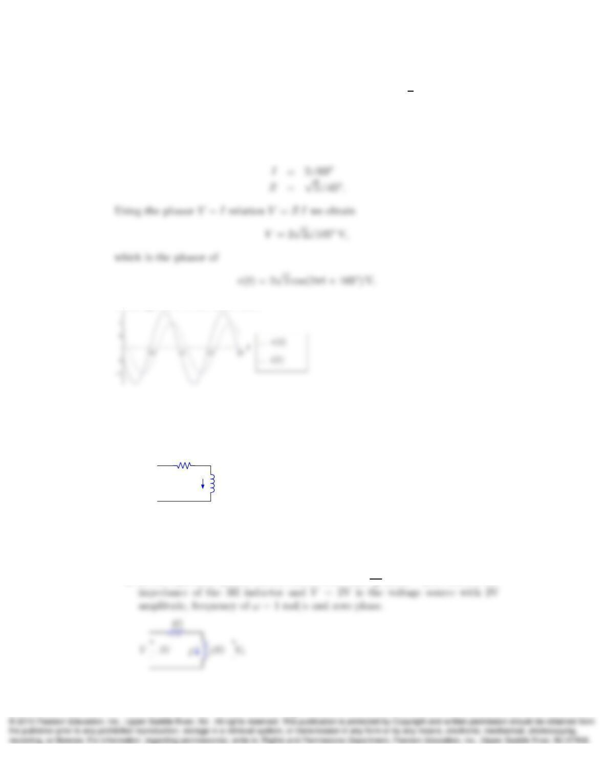
4. A circuit component is conducting a current i(t) = 2 cos(2πt +π
3)A and its imped-
ance is Z= 1 + jΩ. Plot i(t)and the voltage drop v(t)in the current direction as
a function of time for 0≤t≤2s.
Solution:
Converting to phasors
Plotting both in the same axes
5. a) Calculate the series equivalent impedance of the following network for ω= 1
rad/s in rectangular and polar forms and determine the steady-state current
i(t), given that v(t) = 2 cos(t)V:
i(t)3H
+
–
v(t)+
–
vL(t)
4Ω
b) What is the phasor of the inductor voltage vL(t)in this network, given that
v(t) = 2 cos(t)V?
Solution:
a) In the equivalent phasor circuit shown below, j(1rad
3
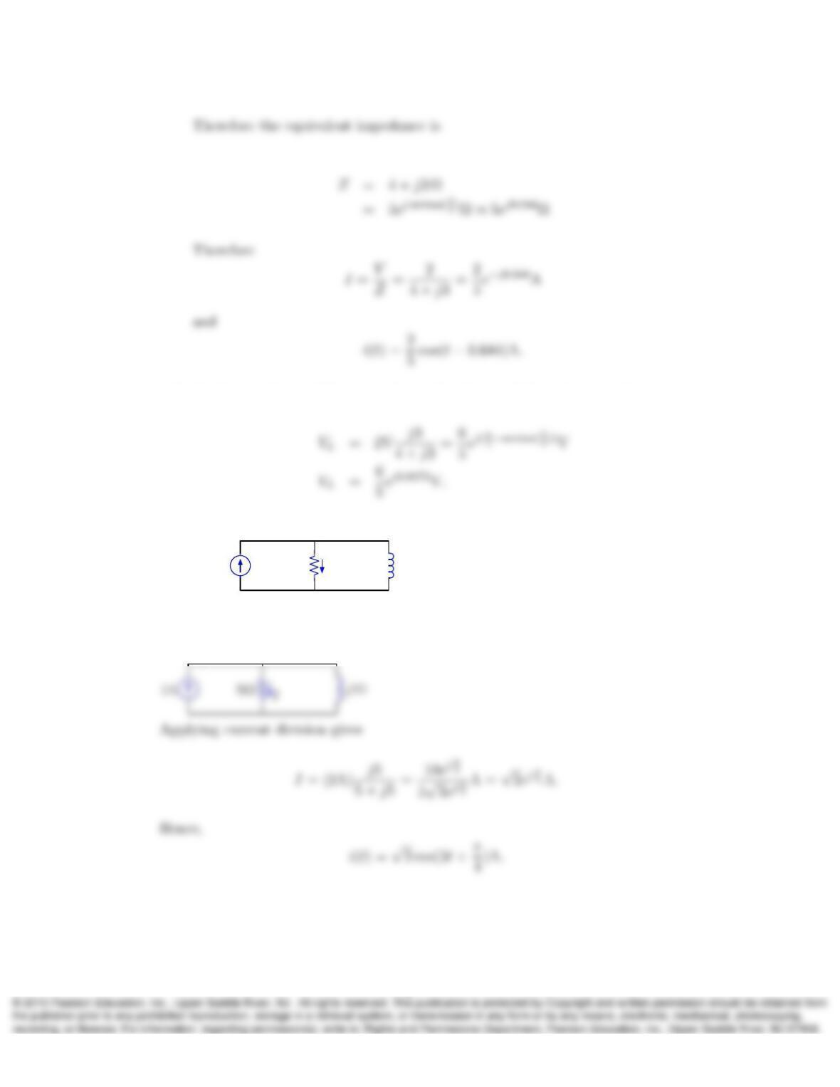
b) Applying voltage division we obtain the phasor of the inductor voltage,
6. Consider the following circuit:
i(t)
2 cos(5t)A 5Ω 1H
Determine the steady-state current i(t)using phasor current division.
Solution:
The equivalent phasor circuit is shown below:
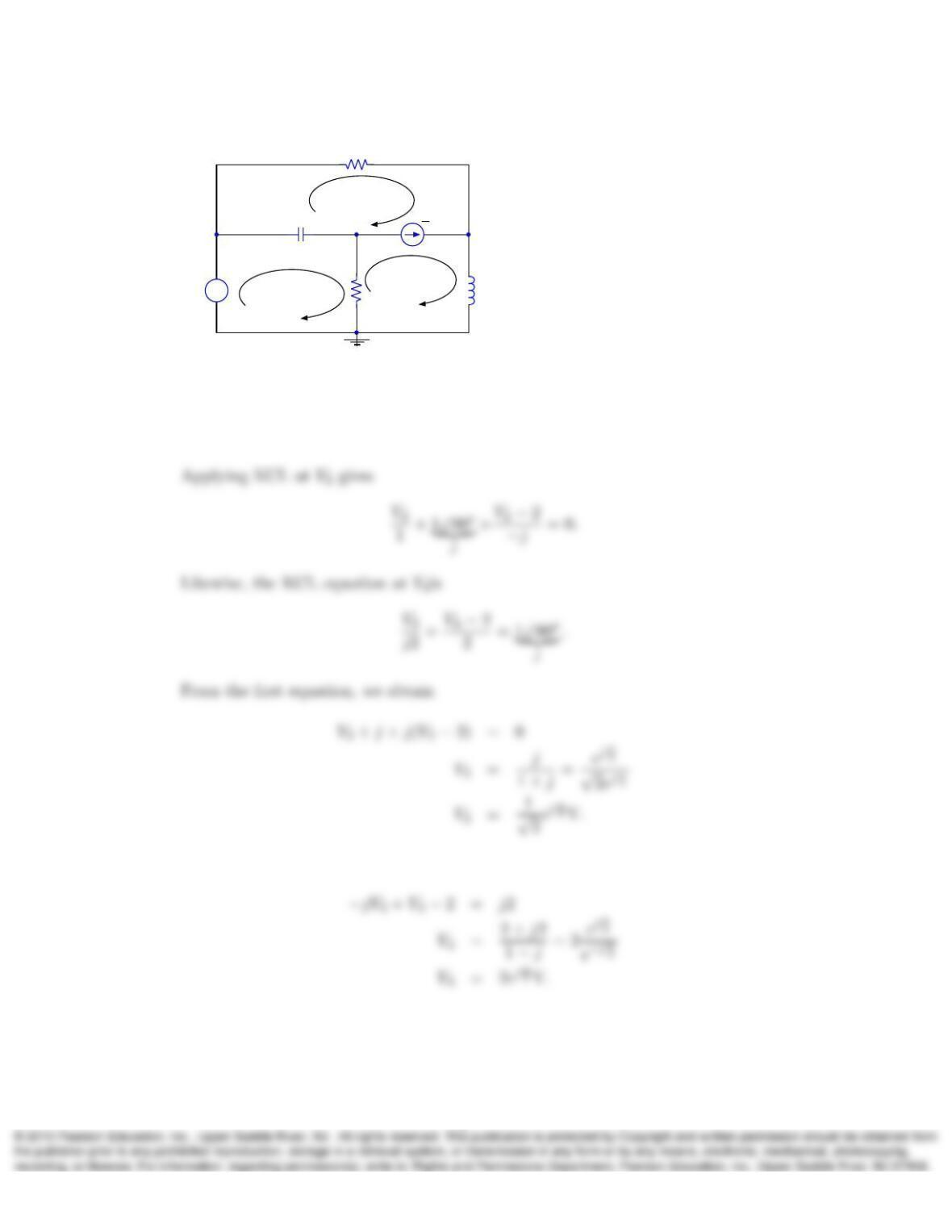
7. In the following circuit determine the node-voltage phasors V1,V2, and V3and
express them in polar form.
4
+
–I3
2V
1690oA
2Ω
1Ω
−j1Ω
V1
V2
I1
I2
j2Ω
V3
Solution:
V1can be determined directly from the circuit,
V1= 2V.
From the second equation, we have
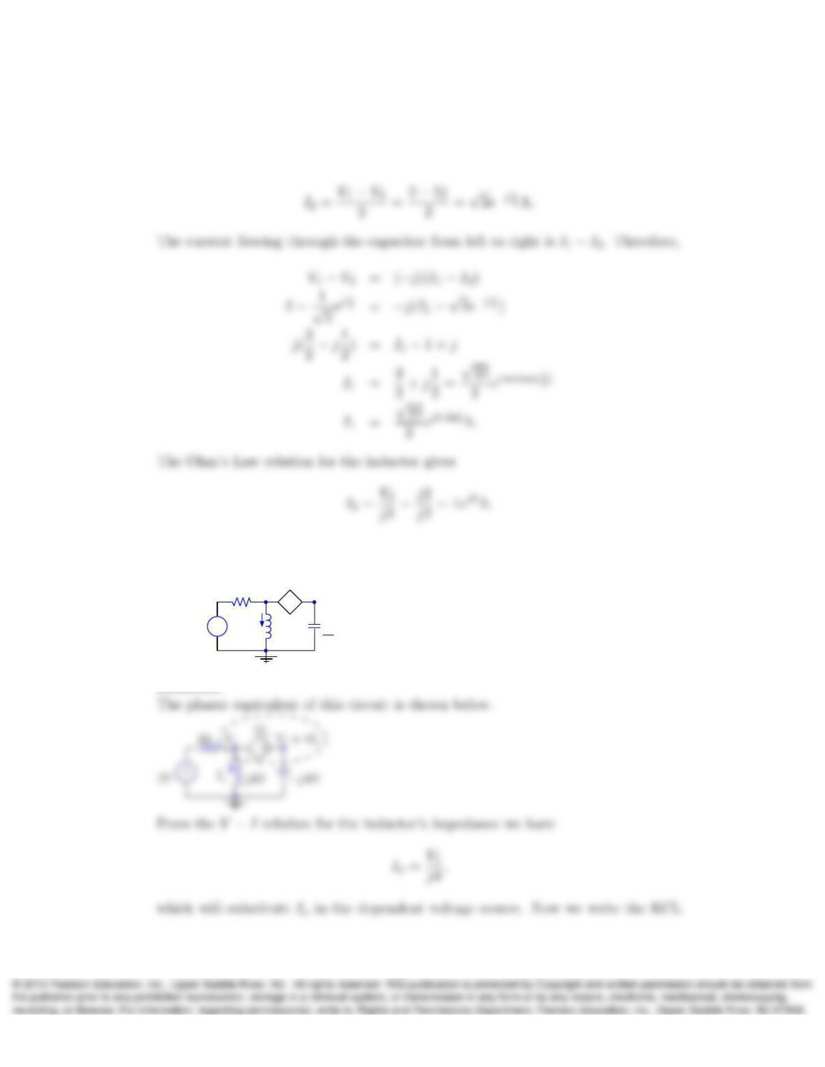
8. In the circuit shown for Problem 7, determine the loop-current phasors I1,I2, and
I3and express them in polar form.
5
Solution:
Using the value of the node-voltage phasors we first determine the value of I2, since
this is the total current flowing through this resistance
9. Use the phasor method to determine v1(t)in the following circuit:
+
–
+
–v2(t)
2 cos(4t)V
2Ω 4ix(t)
ix(t)
1H
1
16F
v1(t)
Solution:
6
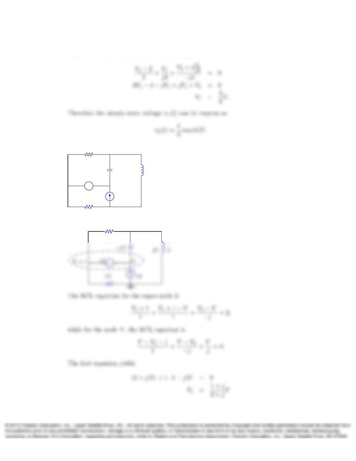
equation for the super-node shown in the figure
10. In the following circuit determine the phasor Vand express it in polar form:
+
–
1Ω
1Ω
−jΩjΩV
1V
2A
+
–
Solution:
1Ω
V
7
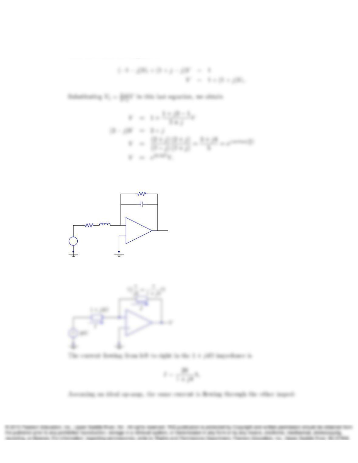
while the second one simplifies to
11. Use the phasor method to determine the steady-state voltage v(t)in the following
op-amp circuit:
+
–
+
–20 cos(4t) V
1Ω
1Ω
1H
2F
v(t)
Solution:
The phasor equivalent of this circuit is
8
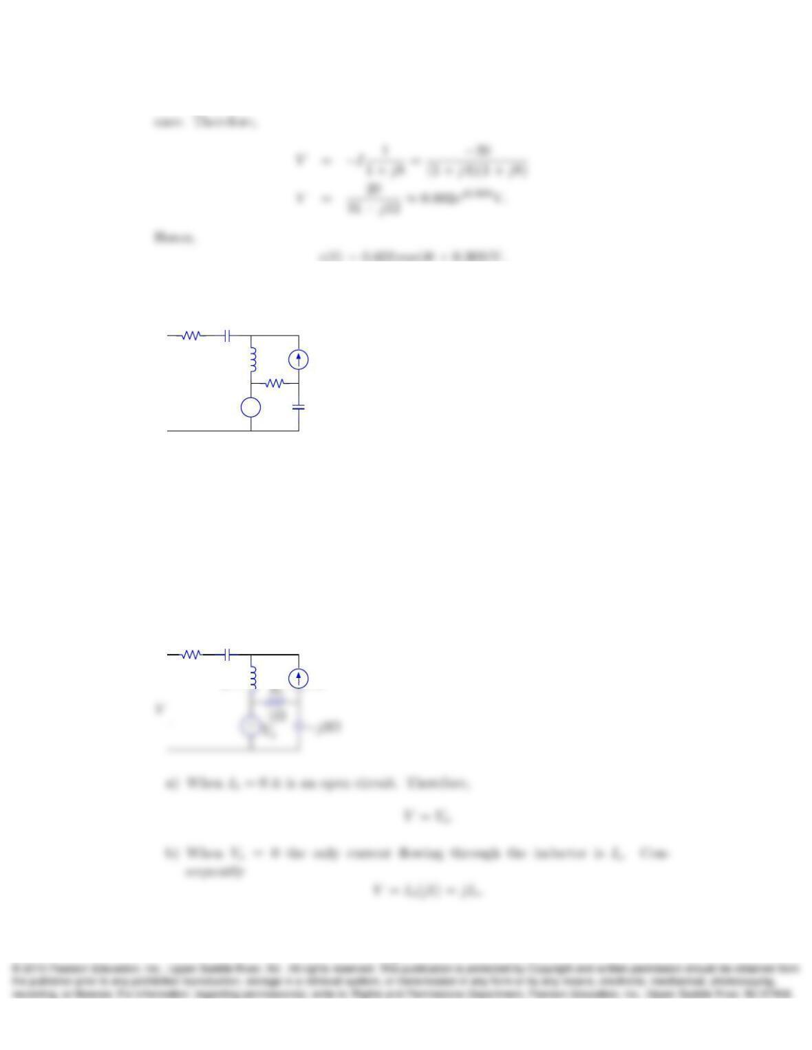
12. Use the following network to answer (a) through (d):
+
–
+
–
V
Vs
Is
1Ω
j1Ω
1Ω −j3Ω
−j1Ω
a) Determine the phasor Vwhen Is= 0.
b) Determine the phasor Vwhen Vs= 0.
c) Determine Vwhen Vs= 4 V and Is=−2A, and calculate the average power
absorbed in the resistors.
d) What is the Thevenin equivalent and the available average power of the net-
work when Vs= 4 V and Is=−2A?
Solution:
+
Is
1Ω
j1Ω
−j1Ω
R1
9
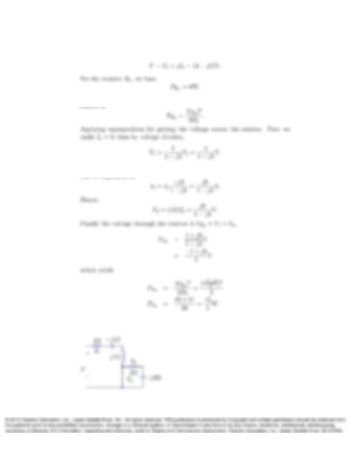
c) By superposition, we have
since no current is flowing through it. For the other resistor, the power ab-
Now we make Vs= 0, then by current division the current through the resistor
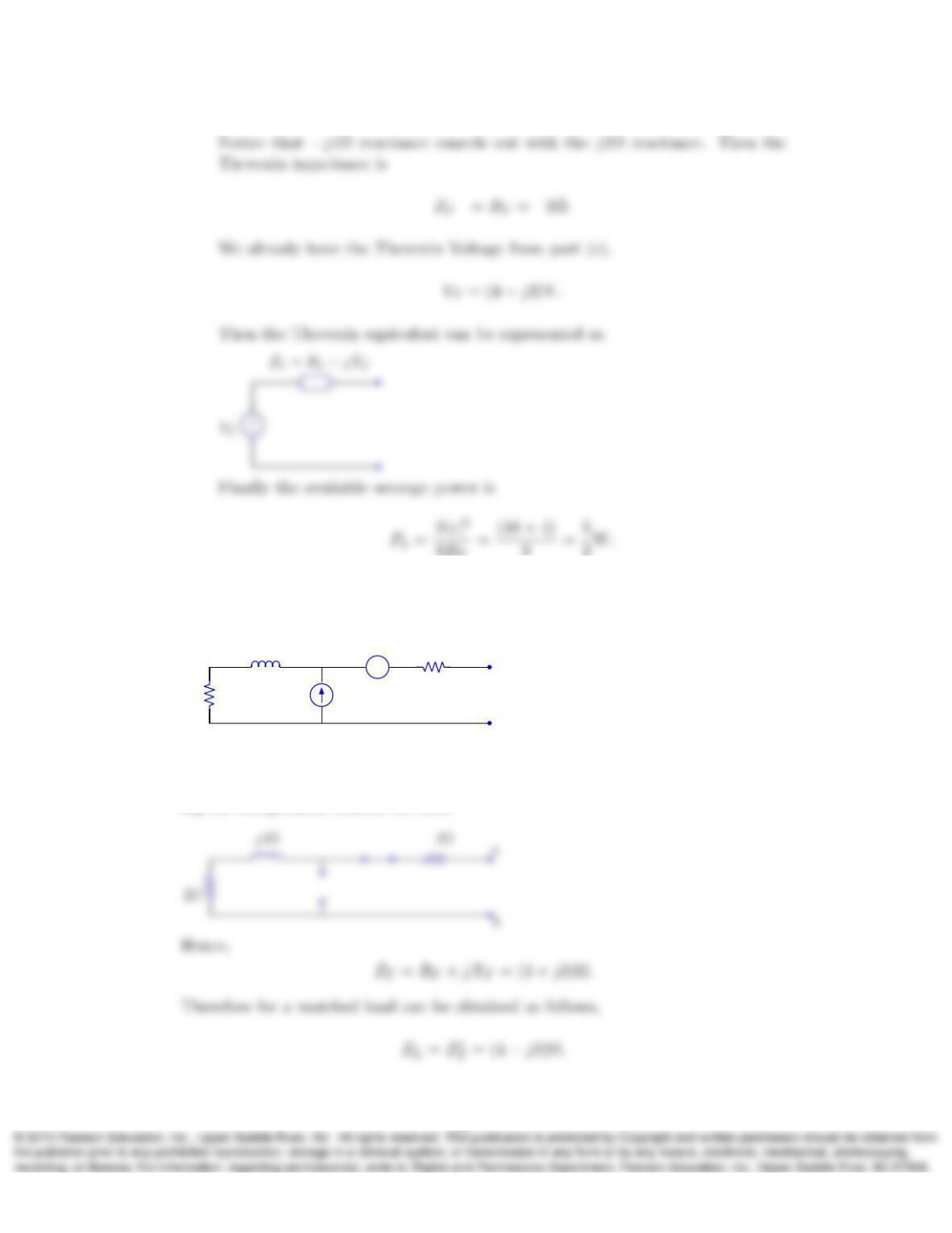
d) For the Thevenin impedance we suppress the independent sources, yielding to
the following circuit:
10
13. Determine the impedance ZLof a load that is matched to the following network at
terminals aand b, and determine the net power absorbed by the matched load:
+
–
b
2Ω
2Ω
2A
jVj3Ω a
Solution:
To determine ZLwe first need to calculate the Thevenin impedance ZT. Suppress-
ing the independent sources we have:
11
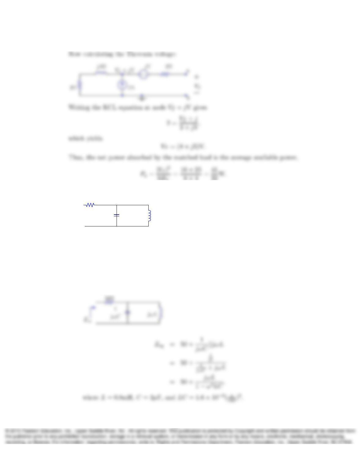
14. a) Calculate the equivalent impedance of the following network for (i) ω= 5
krad/s, (ii) ω= 25 krad/s, and (iii) ω= 125 krad/s:
0.8mH
50Ω 2µF
b) Assuming a cosine voltage input to the network, with a fixed amplitude and
a variable frequency ω, at which value of ωis the amplitude of the capacitor
voltage maximized? At the same frequency what will be the amplitude of the
resistor current?
Solution:
a) Finding a general Zeq from the phasor equivalent circuit:
12
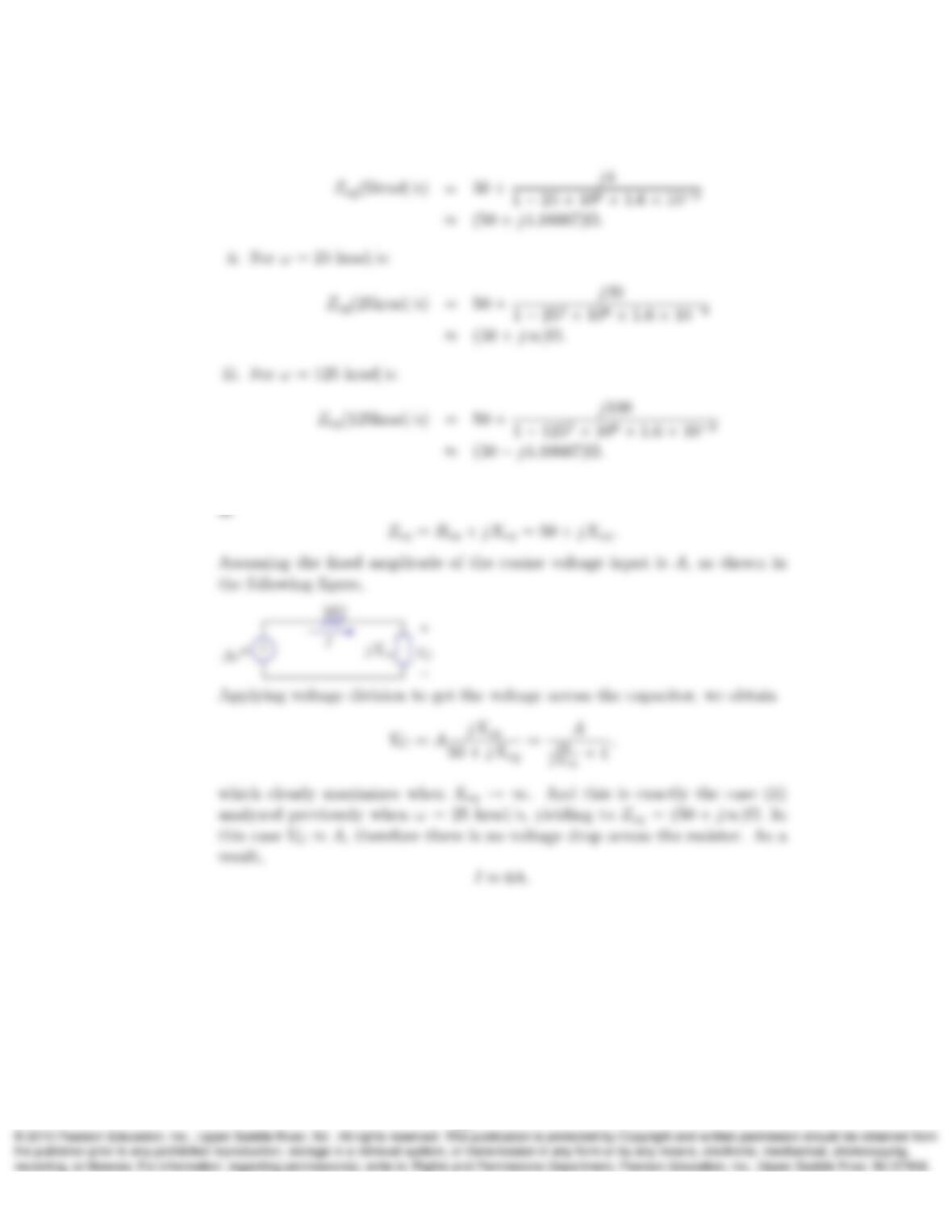
i. For ω= 5 krad/s:
b) From the previous part we have that the equivalent impedance can be written
13