Chapter 3
1. a) In Figure 3.3a, given that i+≈0, what happens to the current vo
RLin the
circuit? Hint: the answer is related to the answer of part (b).
b) For vs= 1 V, Rs= 50 Ω, and RL= 1 kΩ, what is the power absorbed by
resistor RLin the circuit shown in Figure 3.3a and where does that power
come from?
Solution:
a) In the following circuit the biasing connections are shown
+
–
o
vo≈vs
Rs
vb
+
–
vb
i+≈0
2. a) Confirm that the substitution of linear op-amp model of Figure 3.1b into the
non-inverting amplifier circuit of Figure 3.2b leads to the following circuit
diagram:
+
–+
–
+ –
v−
vs
vx
Avx
vo
Ro
R1
R2
Ri
Rs
v+
b) Assuming that A≫1,Ri≫Rs, and Ri≫Ro, show that vo≈(1 + R1/R2)vs
in the equivalent circuit model shown above.
c) Determine the short circuit current ixin the circuit shown below
+
–+
–
+ –
v−
vs
vx
Avx
ix
Ro
R1
R2
Ri
Rs
v+
1
d) What is the Thevenin resistance RT=vo/ixof the equivalent circuit model
above? Use the results from parts (b) and (c)?
Solution:
a) Op-amp model:
v+vo
io
i+
Non-inverting amplifier:
v+vo
Rs
Substituting the Op-amp model into the non-inverting amplifier:
v+
vo
Rs
b) Since Ri≫Rswe can approximate Rs≈0, so the circuit simplifies to
v−
vo
R1
Ri
v+
2
Likewise, the KCL equation for the output terminal is
c) After the short circuit and considering Ri≫Rsthe circuit becomes:
R1
Ri
v−
3
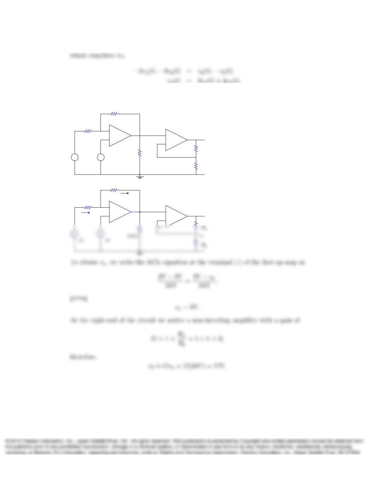
3. In the next circuit shown, determine the node voltage vo(t). You may assume
that the circuit behaves linearly and make use of the ideal op-amp approximations
(v+≈v−and i+≈i−≈0).
+
–
+
–
+
–
vo(t)
v1(t)v2(t)
6kΩ
2kΩ
Solution:
Considering an ideal op-amp we assume no current is flowing through terminal
4
4. In the following circuit, determine the node voltage vousing the ideal op-amp
approximations and assuming that Ra=Rb= 1 kΩ
+
–
+
–
+
–
+
–
2V 4V Rb
Ra
1kΩ
1kΩ
1956Ω
vo
Solution:
+
–
+
–
1kΩ
1kΩ
vo
i
i
va
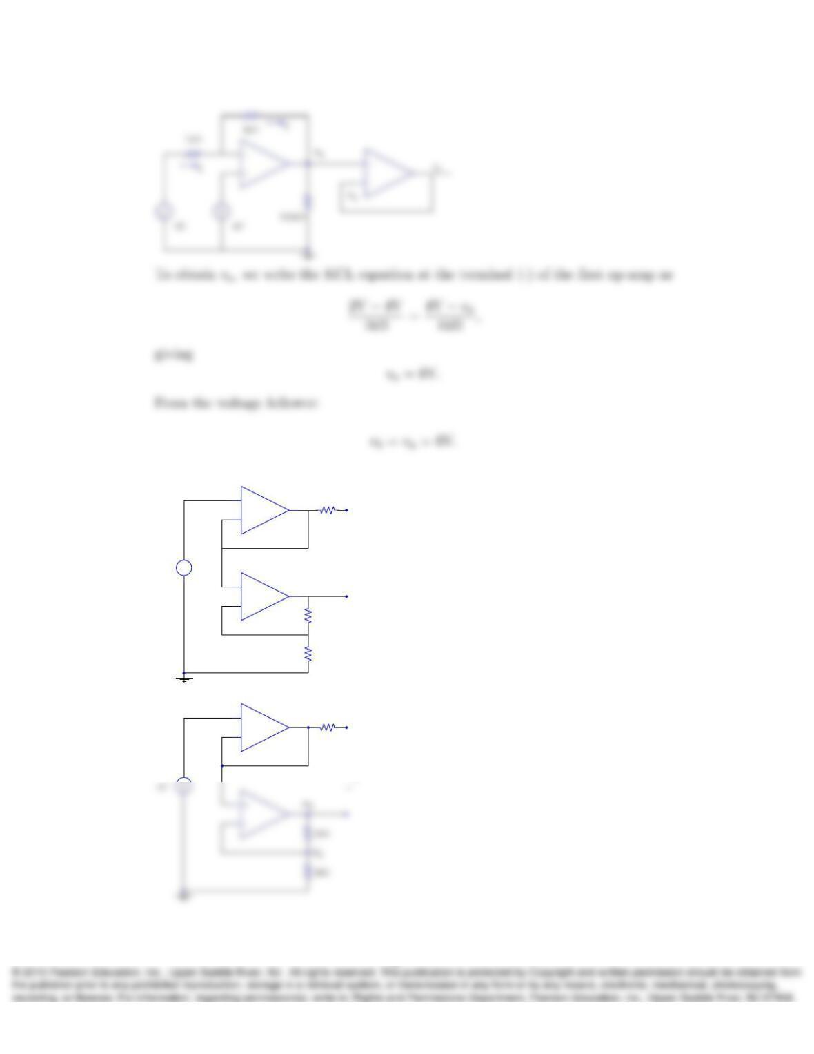
5. Repeat Problem 4 for Ra= 0 and Rb=∞.
Solution:
For this values we obtain at the right-end of the circuit a voltage follower as shown
in the following graph:
5
6. In the circuit shown next, determine the voltage vxassuming linear operation.
2kΩ
+
–
vx
5V
+
–
+
–
+
–
2kΩ
2kΩ
Solution:
2kΩ
+
vx
+
–
v1
v4
6
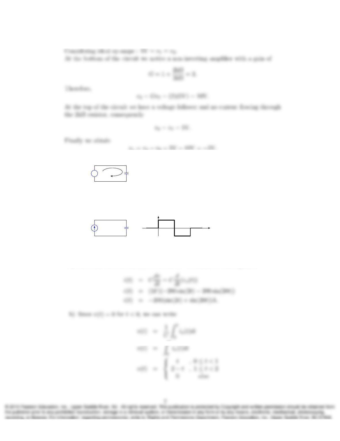
7. a) In the following circuit, determine the capacitor current i(t).
+
–
vs(t)vs(t) = 100 cos(2t) + 10 cos(20t)V
1F
i(t)
(erratum: The book has a wrong figure.)
b) In the next circuit, determine and plot the capacitor voltage v(t). Assume
that v(t) = 0 for t < 0.
is(t)1F
v(t)+
–
is(t),A
2
0
1
1
−1t
Solution:
a) To obtain the current i(t)we use the v−irelation for the capacitor
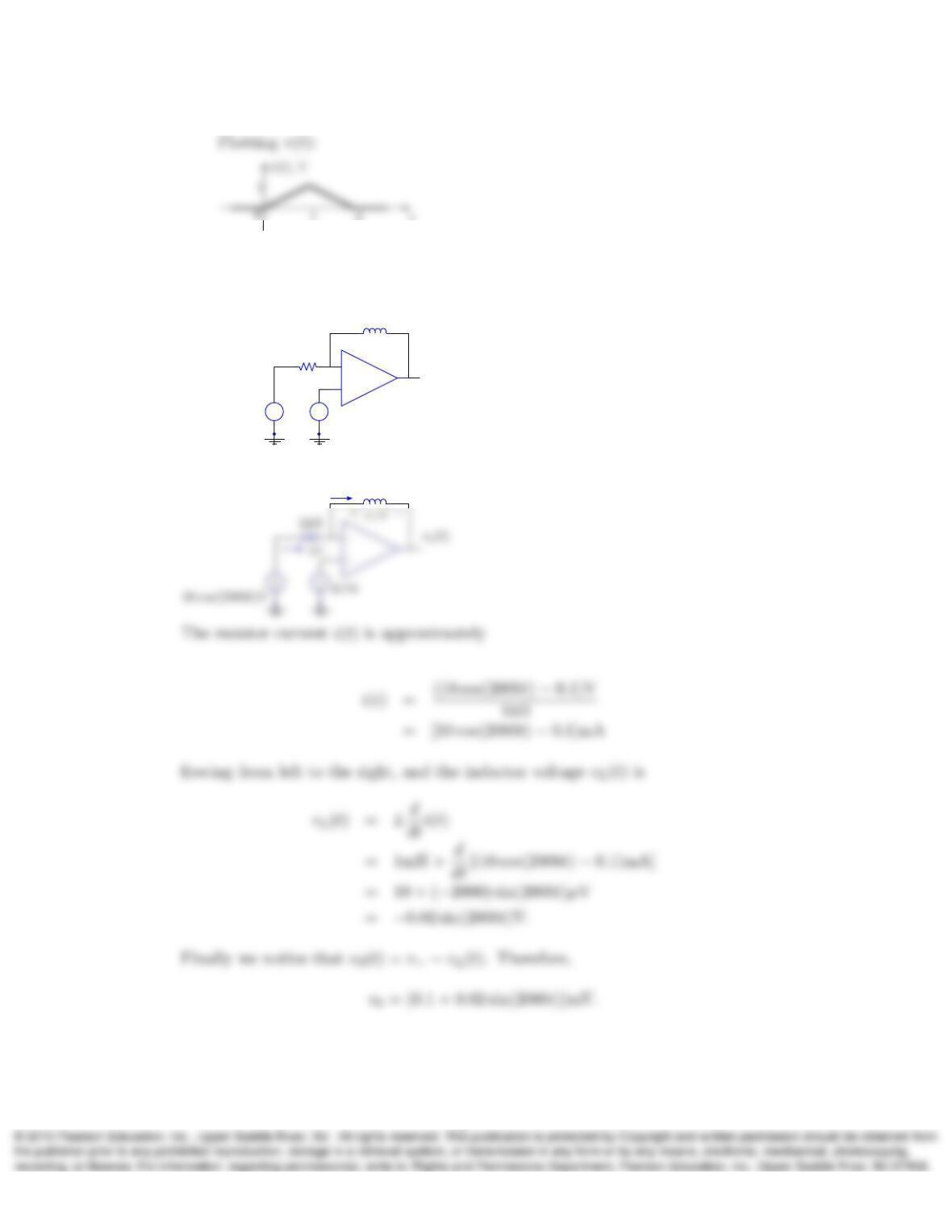
8. In the following circuit, determine the output vo(t)using the ideal op-amp approx-
imations:
+
–
+
–
+
–
vo(t)
10 cos(2000t)V 0.1V
1mH
1kΩ
Solution:
1mH
i(t)
9. In the following circuit, determine vo(t).
8
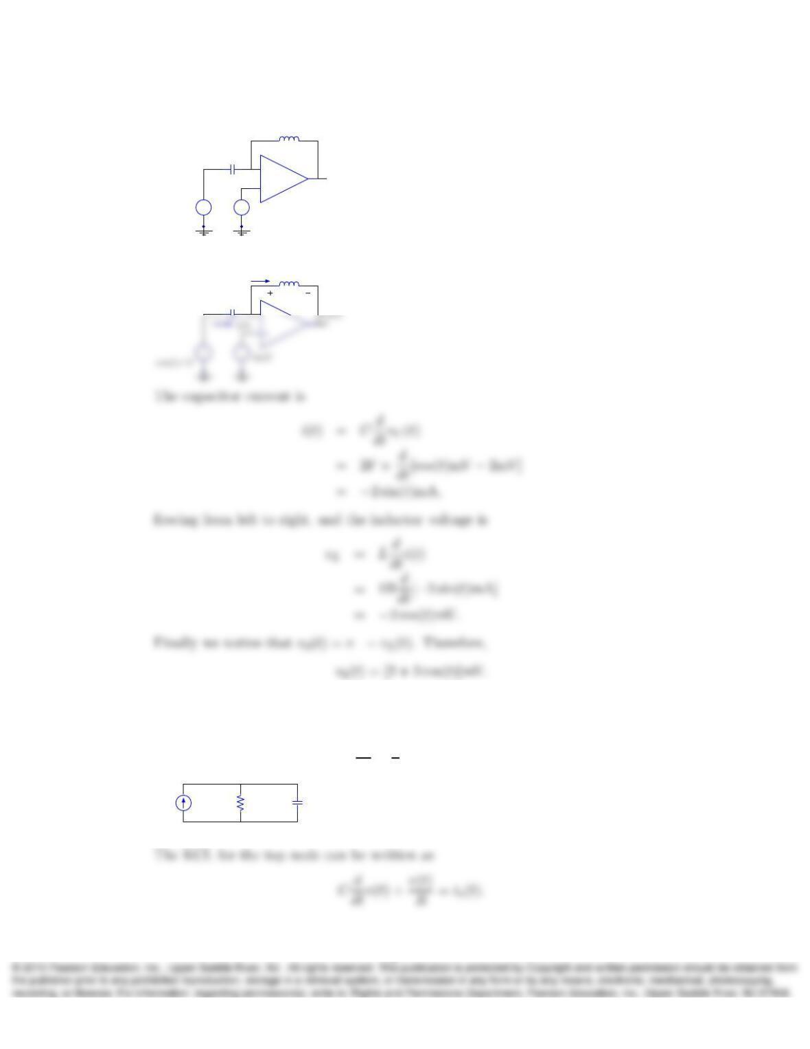
+
–
+
–
+
–
vo(t)
cos(t)mV 2mV
1H
2F
Solution:
1H
2F
i(t)
vL(t)
10. Using KCL and the v−irelations for resistors and capacitors, show that the voltage
v(t)in the following circuit satisfies the ODE
3dv
dt +1
2v(t) = is(t).
v(t)
is(t)2Ω 3F
+
–
Solution:
9
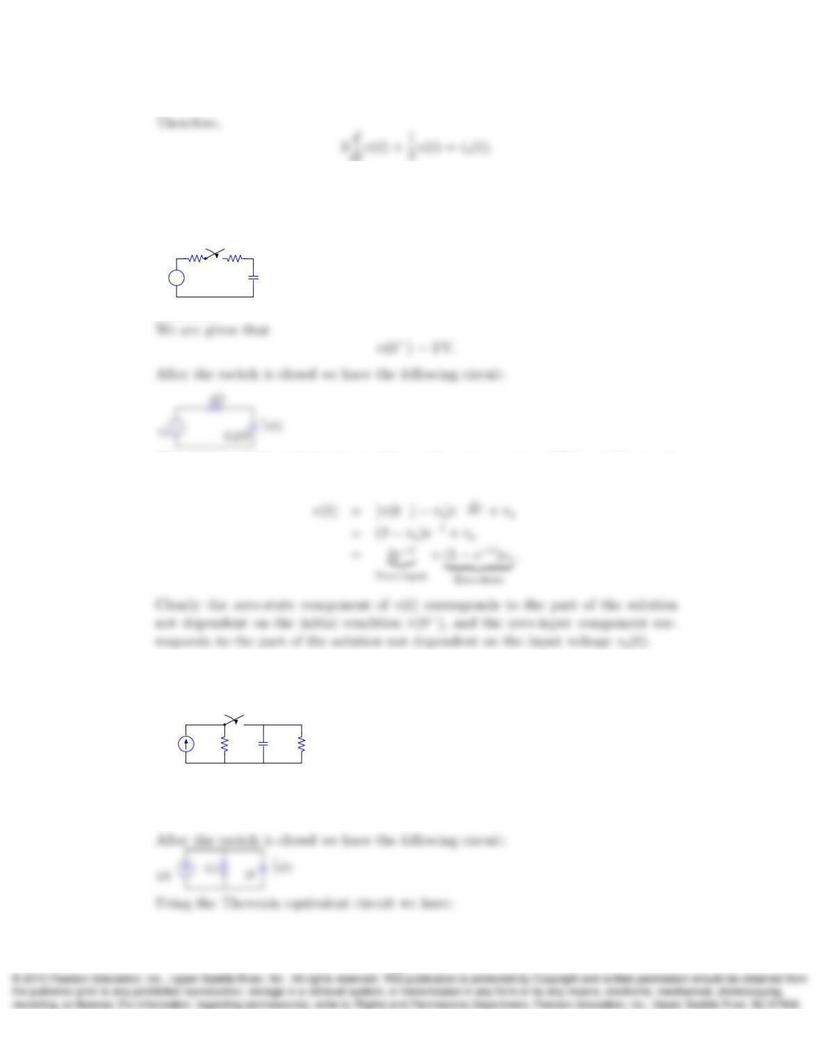
11. In the next circuit, v(t) = 2 V for t < 0. Determine v(t)for t > 0after the switch
is closed, and identify the zero-state and zero-input components of v(t). In the
circuit, vsdenotes a DC voltage source (time-independent).
+
–
vsv(t)
2Ω 2Ω
0.25F
+
–
t= 0
Solution:
The solution to this initial-value problem with a time constant (RC = 1s) for t > 0,
is derived in the book and is
12. In the next circuit, v(t) = 0 for t < 0. Determine v(t)for t > 0after the switch is
closed.
t= 0
v(t)
2A 2Ω 2Ω1F
+
–
Solution:
We are given that
v(0−) = 0 V.
10
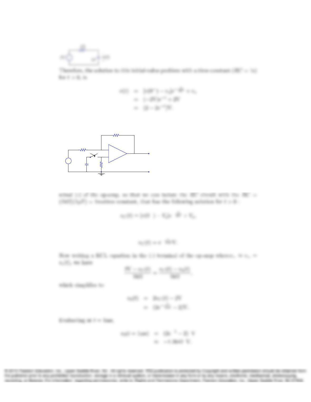
13. Assuming linear operation and vc(0) = 1 V, determine vo(t)at t= 1 ms in the
following circuit:
+
–
vo(t)
2V
+
–
+
–
t= 0
1kΩ
1µF
1kΩ
1kΩ
vc(t)
+
–
Solution:
Assuming linear operation we notice that no current is flowing through the ter-
but in this case Vs= 0 and v(0−) = 1V, which yields to
11
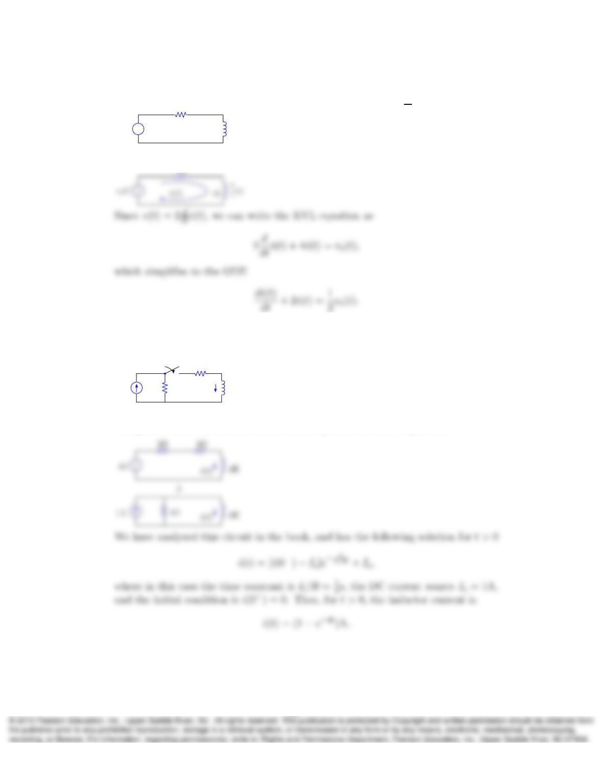
14. Determine the ODE that describes the inductor current i(t)in the next circuit.
Hint: Apply KVL using a loop current i(t)such that v(t) = 2di
dt .
+
–2H
vs(t)4Ω v(t)
+
–
Solution:
4Ω
15. In the circuit that follows, find i(t)for t > 0after the switch is closed. Assume
that i(t) = 0 for t < 0.
t= 0
i(t)
2A 2Ω
2Ω
1H
Solution:
Using source transformations we can come up with the following circuit:
16. The circuit shown next is in DC steady state before the switch flips at t= 0. Find
vL(0−)and iL(0−), as well as iL(t)and vL(t), for t > 0.
12
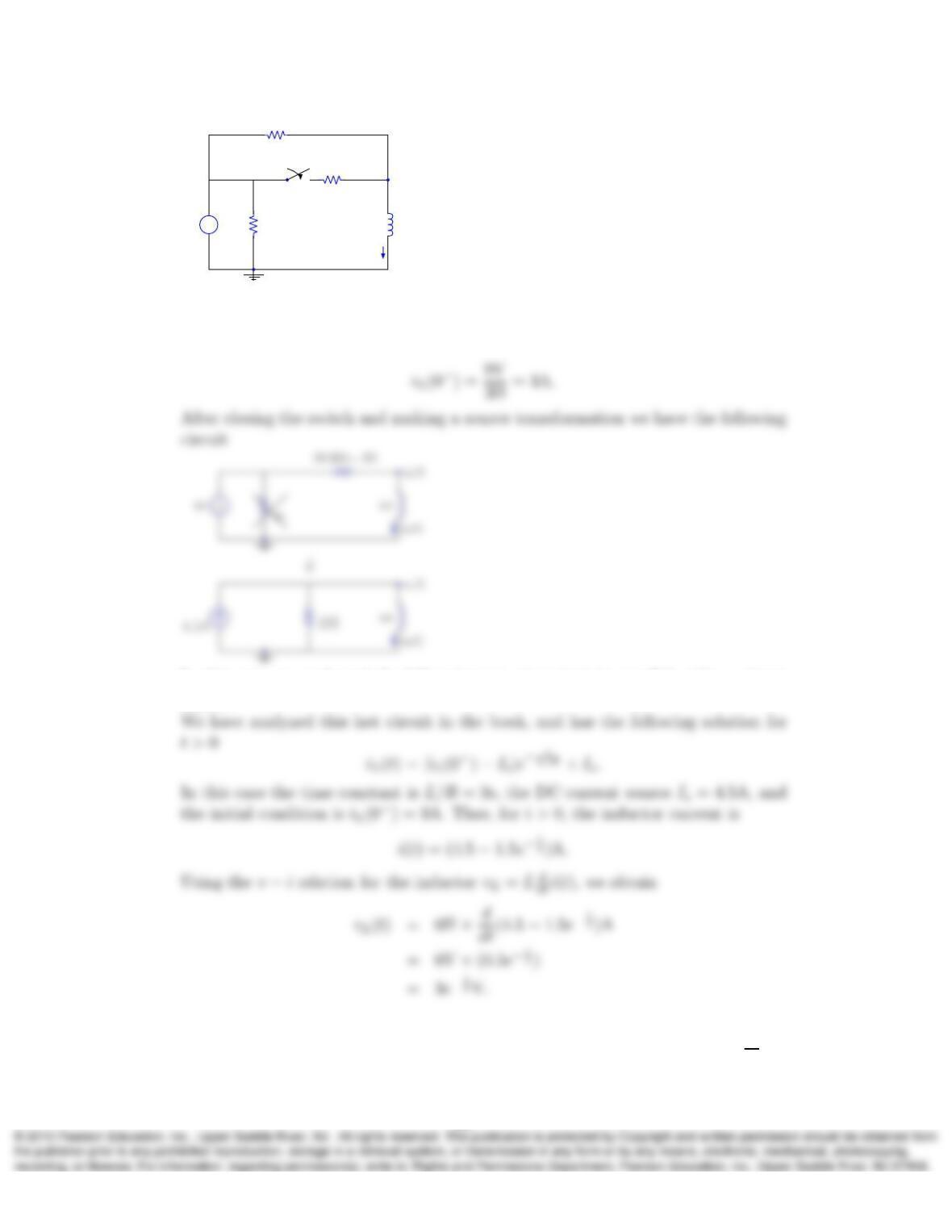
vL(t)
3Ω
6H5Ω
+
–
t= 0
6Ω
iL(t)
9V
Solution:
In the DC steady-state, before closing the switch, the inductor acts as a short
circuit, then vL(0−) = 0V. Therefore by Ohm’s Law we have our initial condition
In this case we neglected the 5 Ω resistance, since it is in parallel with a voltage
source.
17. Obtain the second-order ODE describing the capacitor voltage v(t)in the series
RLC circuit shown next. Hint: Proceed as in Problem 14 and use i(t) = 2dv
dt for
13
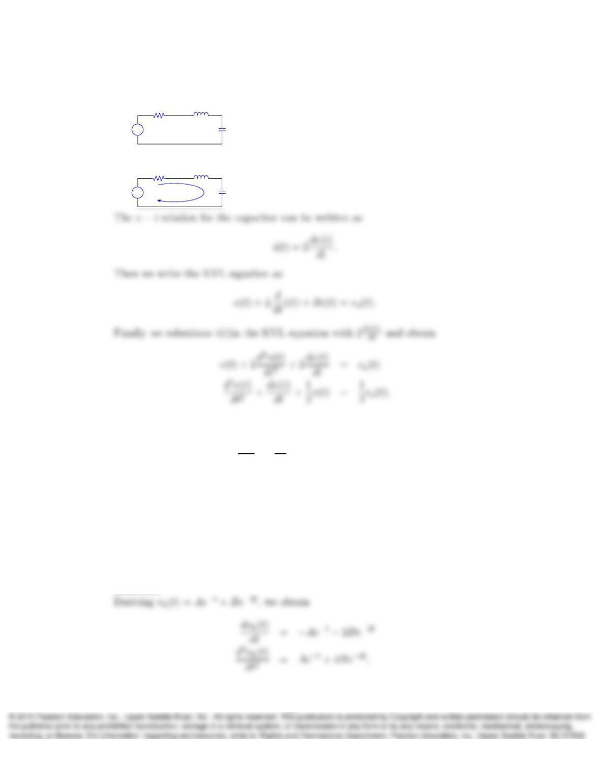
the loop current.
+
–
1Ω
vs(t)2F v(t)
+
–
1H
Solution:
+
–
1Ω
vs(t)2F v(t)
+
–
1H
i(t)
18. A second-order linear system is described by
d2v
dt2+ 3dv
dt + 2v(t) = cos(2t).
Confirm that the transient function
vh(t) = Ae−t+Be−2t
is the homogeneous solution of the ODE and its particular solution can be expressed
as
vp(t) = Hcos(2t+θ).
Determine the values of Hand θ. Hint: See Example 3.20 in Section 3.4.3.
Solution:
14
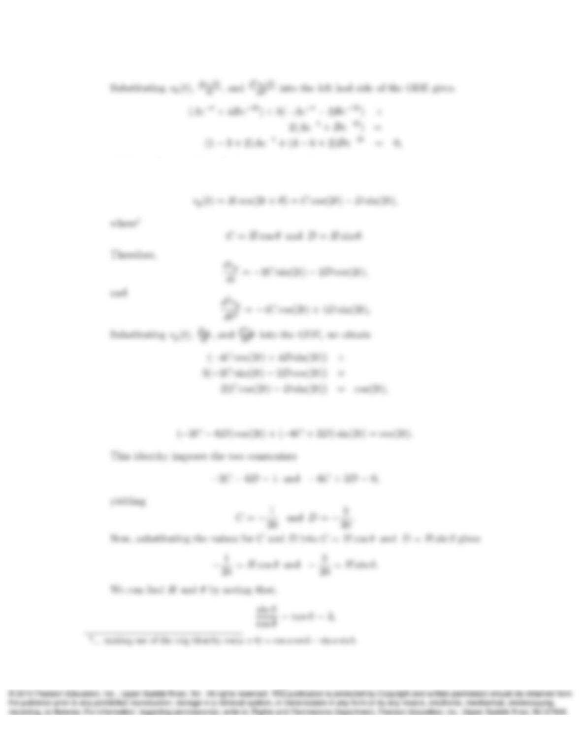
which confirms vh(t)as the homogeneous solution.
For the particular solution we use
or equivalently,
15
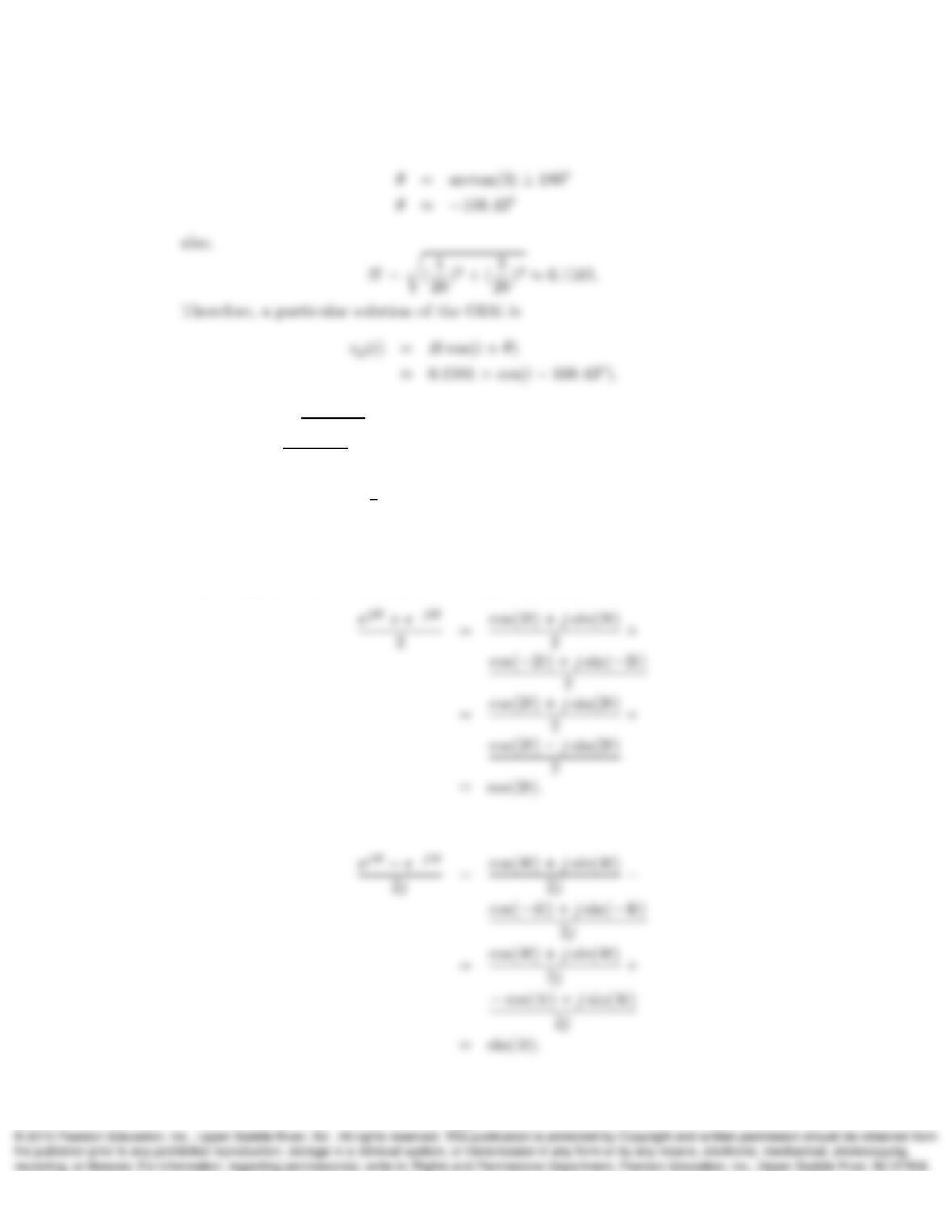
and taking into account that cos(θ)<0,
19. a) Show that ej2t+e−j2t
2= cos(2t).
b) Express ej4t−e−j4t
2jin terms of a sine function.
c) Given that −4(ej3t+e−j3t) = Acos(3t+θ), determine A > 0and θ.
d) Express P=Re{2ejπ
3ej5t}in terms of a cosine function.
Solution:
a) Using the Euler’s identity (ejt = cos(t) + jsin(t)), we have
b) Using Euler’s identity, yields
16
c) Using result form (a), we obtain
comparing with Acos(3t+θ),
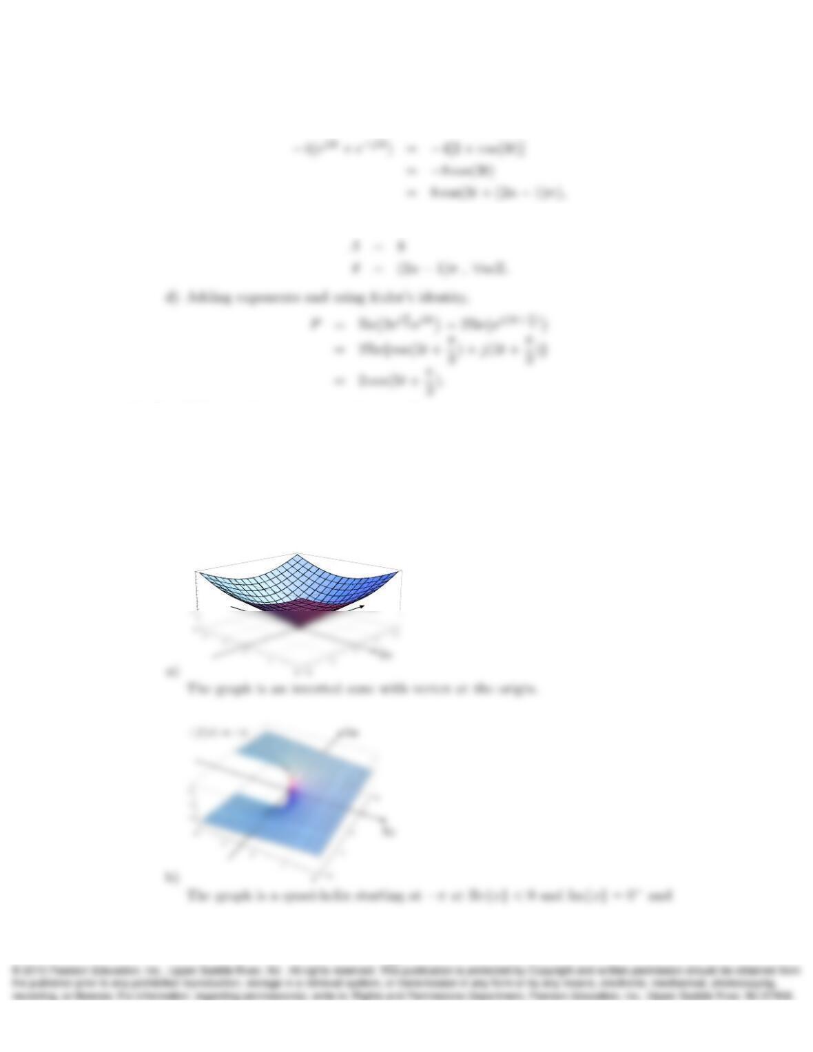
20. Let f(x) = xwhere xis a complex variable.
a) Sketch the surface |f(x)|over the 2-D complex plane. Describe in words what
the surface looks like.
b) Describe in words the appearance of the surface ∠f(x).
Solution:
10
15
Im
|f(x)|=|x|
17

21. Let f(x) = x−(2 + j3). Sketch the surface |f(x)|over the 2-D complex plane and
describe in words what the surface looks like.
Solution:
|f(x)|=|x−(2 + j3)|
18