Chapter 2
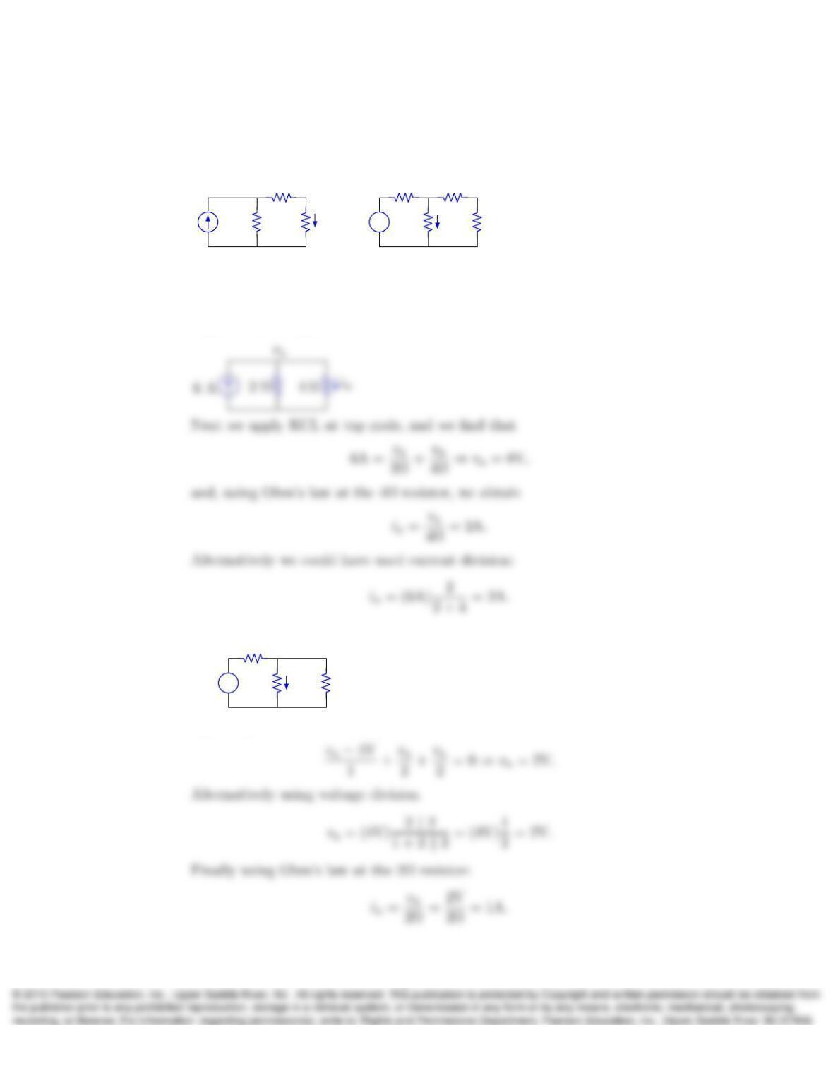
1. In the following circuits, determine ix:
+
–ix
6A4 V
1 Ω 1 Ω 1 Ω
2 Ω 2 Ω 1 Ω
3 Ω
ix
(a) (b)
Solution:
a) First we label the top left node as vaand combine the resistors 1Ωand 3Ωas
depicted in the figure:
b)
+
–ix
4 V
1 Ω
2 Ω 2 Ω
va
Applying KCL at node va, we obtain
1
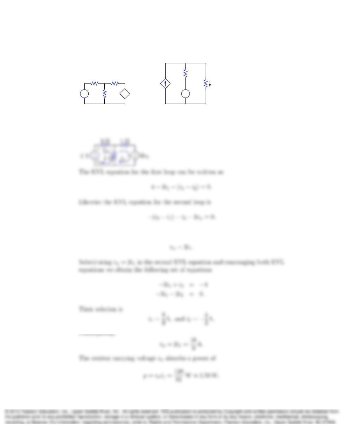
2. In the following circuits, determine vxand the absorbed power in the elements
supporting voltage vx:
+
–
4 V
2 Ω 1 Ω
1 Ω 2vx
+
–
vx
+ –
+
–
2 Ω
2 Ω
2 V
vx
+
–iy
3iy
(a) (b)
Solution:
a) First we assume the directions of the two loop currents to be clockwise:
Note that applying Ohm’s law in the 2Ωresistor, we can express vxas
2
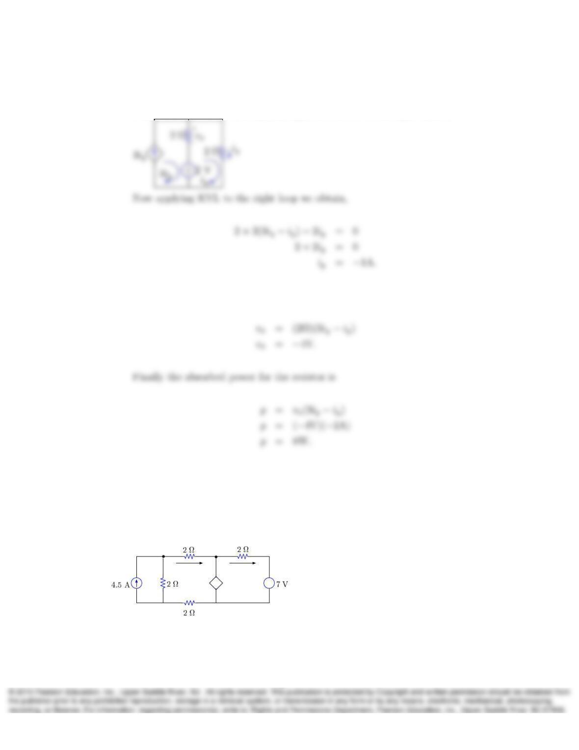
b) First we assign the currents of the two loops to be equal to 3iyand iy, since
this values coincide with the current flowing out from the dependent current
source and the current flowing through the resistor in the right branch.
Next applying Ohm’s law to the resistor in the middle branch, we have
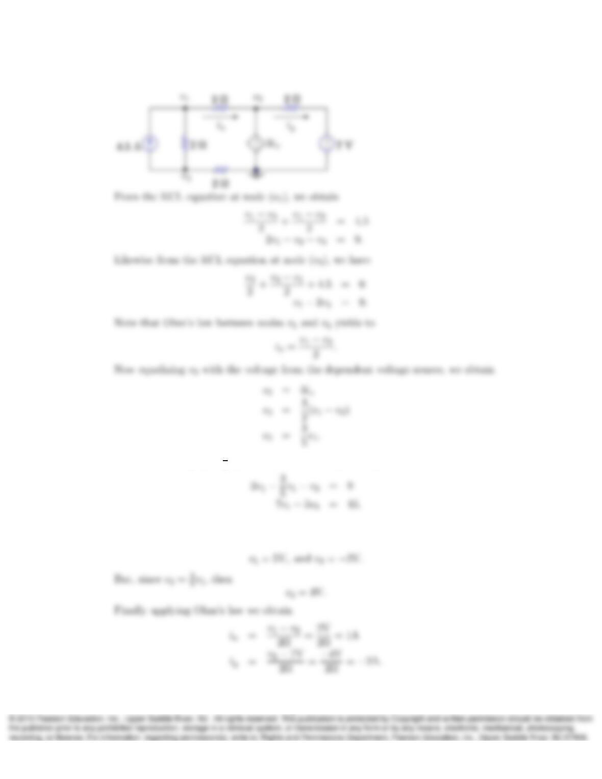
3. In the circuit shown next, determine v1,v2,ix, and iyusing the node voltage
method. Notice that the reference node has not been marked in the circuit; there-
fore, you are free to select any one of the nodes in the circuit as the reference. The
position of the reference (which should be shown in your solution) will influence
the values obtained for v1and v2but not for ixand iy.
+
–
+
–
v1v2
iy
ix
3ix
Solution:
We decide our reference to be in the bottom right node as depicted in the figure:
3
Now substituting v2=3
5v1into the first KCL equation gives
This last equation forms with the second KCL equation a set of two linear equations
with two unknowns. Their solution is
4
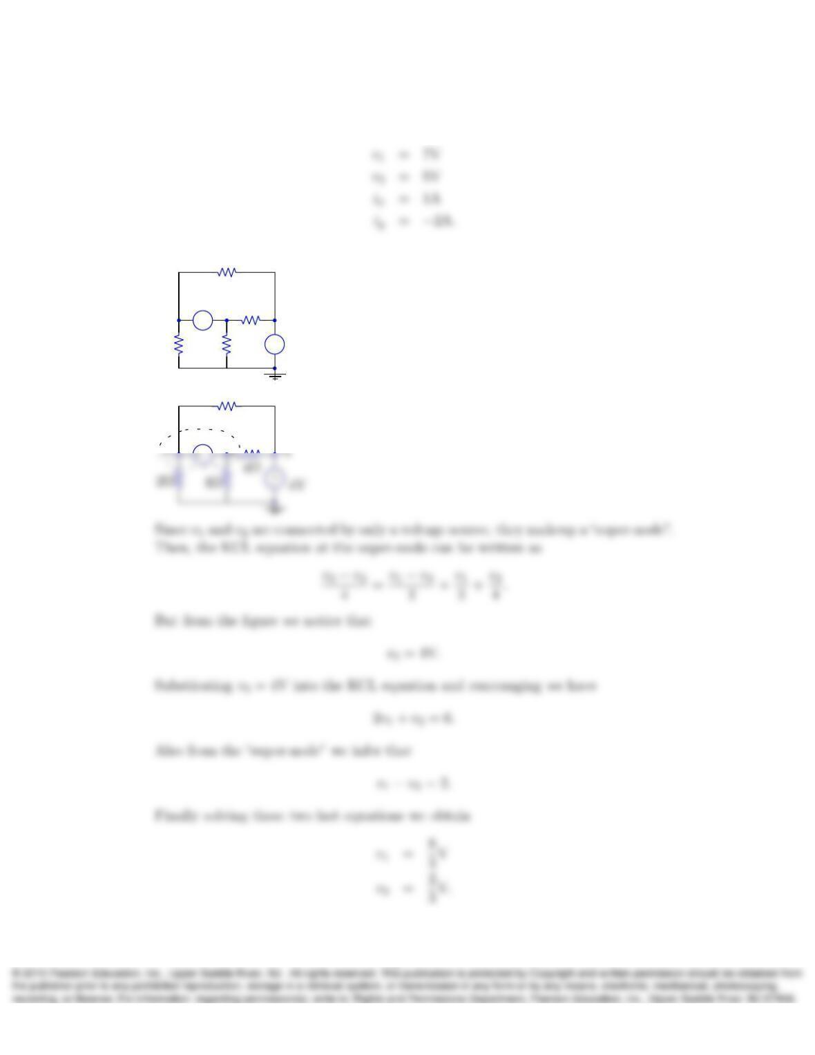
In the case of placing the ground at v3then we obtain
4. In the following circuit, determine the node voltages v1,v2, and v3:
+
–
+
–
v3
2Ω
2Ω
4Ω
4Ω
4V
2V
v1v2
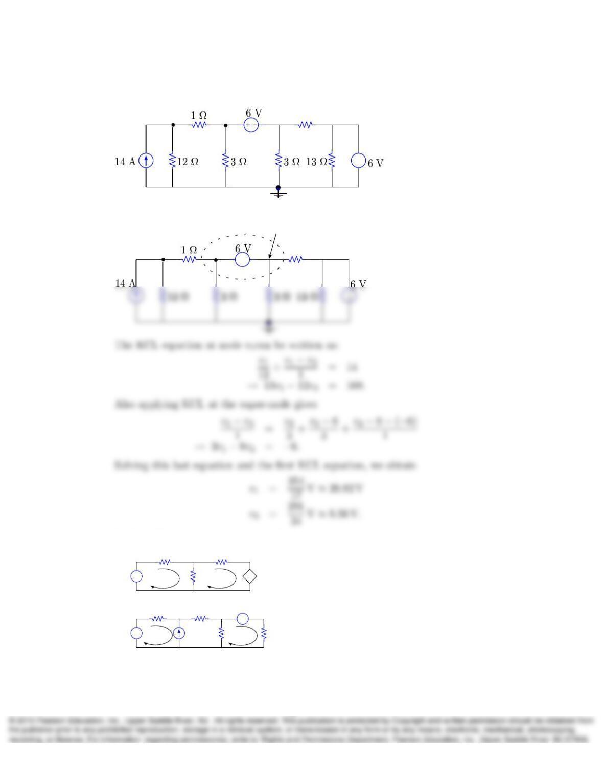
Solution:
+
2Ω
2V
5
5. In the following circuit determine node voltages v1and v2:
+
–
v2
v11 Ω
Solution:
+
–
v2
v1
(v2−6)
−6V
supernode
1 Ω
6. In the following circuits determine loop currents i1and i2:
4 V
2 Ω
i1
+
–+
–
+
–
+
–
3 Ω
4 Ω 2i1
4 V
6 V
2 Ω
2 Ω
1 Ω
1 Ω
2 A
i1i2
i2
b)
a)
Solution:
6
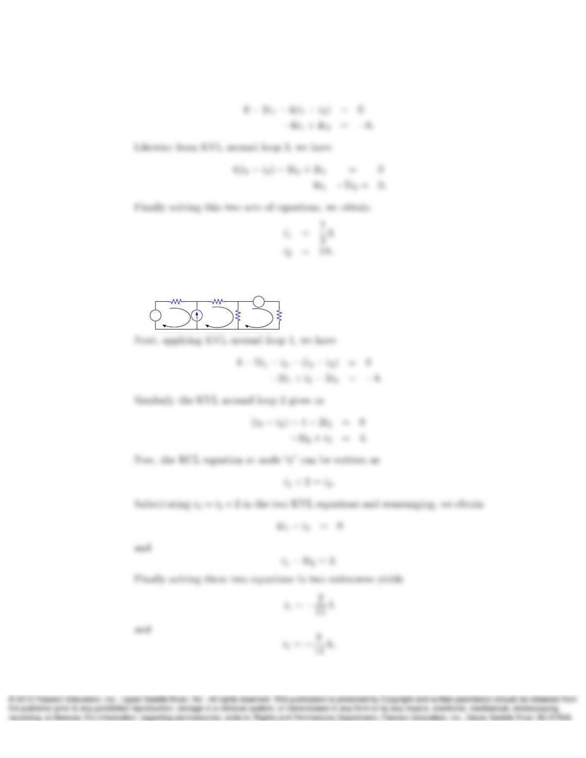
a) Writing the KVL equation around loop 1 and simplifying, we have
b) First we assume another loop current i3as depicted in the following figure:
4 V i1
+
–
+
–
4 V
2 Ω
2 Ω
1 Ω
1 Ω
2 A i2
i3
a
7.
7
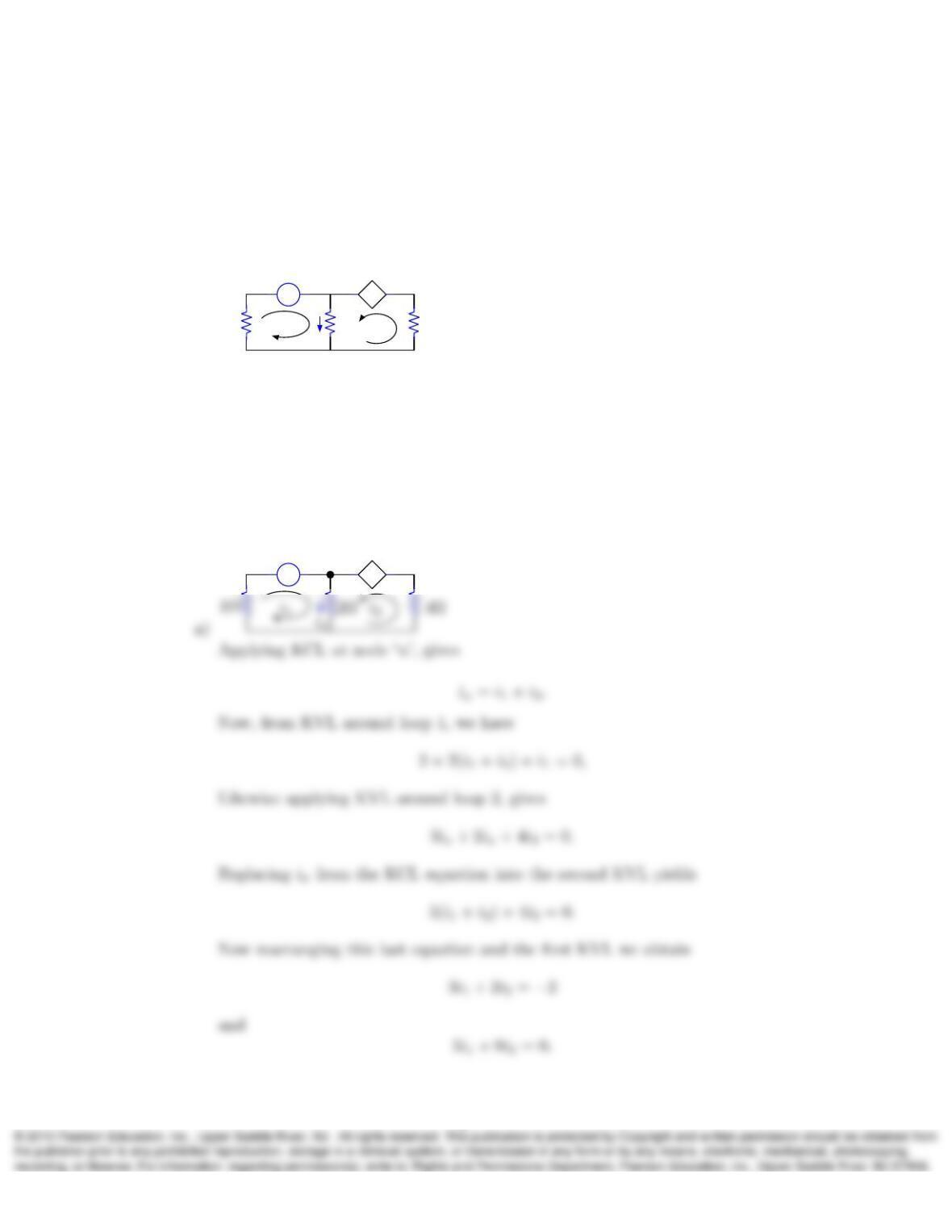
a) For the next circuit, obtain two independent equations in terms of loop-
currents i1and i2and simplify them to the form
Ai1+Bi2=E
Ci1+Di2=F,
i1
1Ω 2Ω i2
ix
+
–
+
–
2V 3ix
4Ω
b) Express the previous equations in the matrix form
A B
C D i1
i2=E
F
and use matrix inversion or Cramer’s rule to solve for i1and i2.
Solution:
+
–
+
–
2V 3ix
a
8
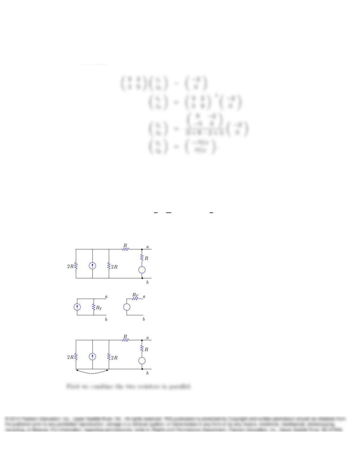
b) Expressing the last two equations in matrix form and using matrix inversion,
we obtain
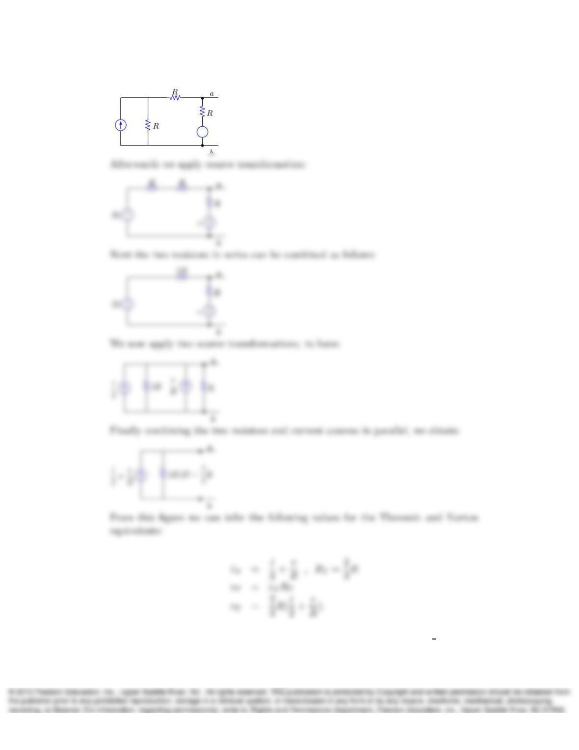
8. By a sequence of resistor combinations and source transformations, the next circuit
shown can be simplified to its Norton (bottom left) and Thevenin (bottom right)
equivalents between nodes aand b. Show that
iN=i
2+v
Rand RT=2
3R
and obtain the expression for vT.
+
–
+
–
vT
iv
iN
Solution:
+
–
iv
parallel resistors
9
+
–
iv
9. In the following circuit it is observed that for i= 0 and v= 1 V, iL=1
2A, while
10
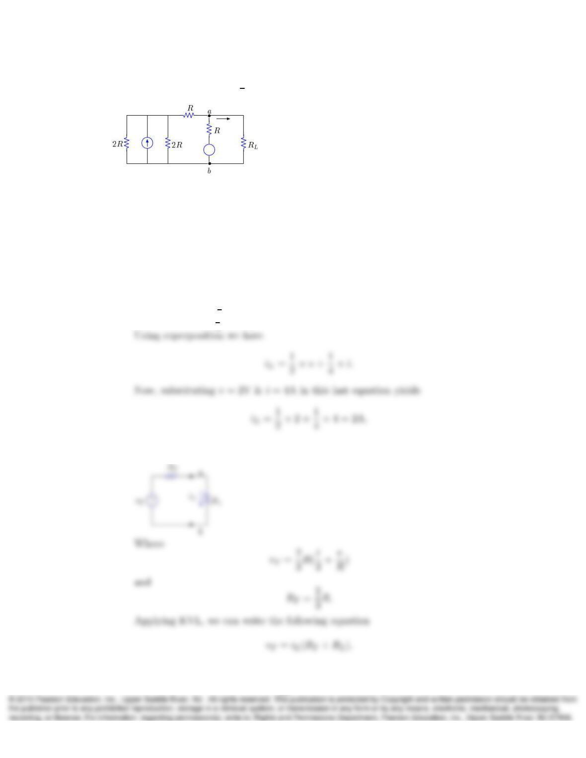
for i= 1 A and v= 0,iL=1
4A.
+
–
iL
iv
a) Determine iLwhen i= 4 A and v= 2 V (you do not need Rand RLto answer
this part; just make use of the results of Problem 8).
b) Determine the values of resistances Rand RL.
c) Is it possible to change the value of RLin order to increase the power absorbed
in RLwhen i= 4 A and v= 2 V? Explain.
Solution:
a) v= 1 contributes 1
2A to iL
i= 1 contributes 1
4A to iL
b) Using the result from exercise 8, we have
11