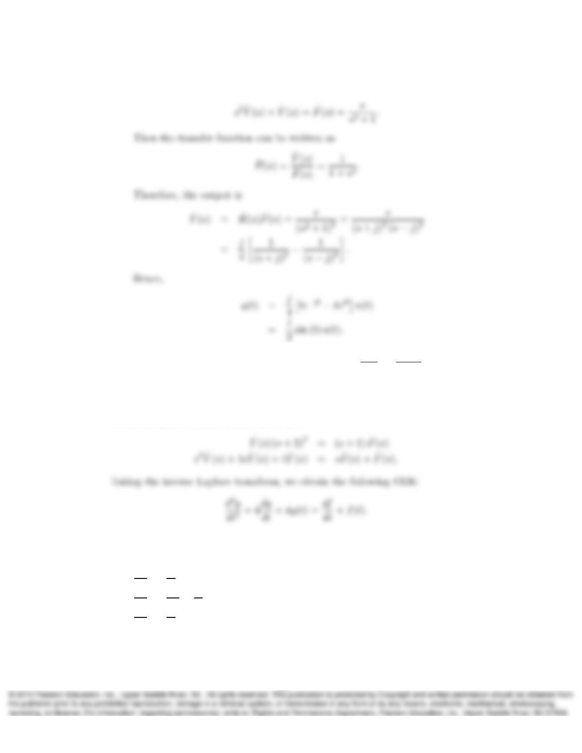
c) Taking the Laplace transform with zero initial conditions, we obtain
14. If an LTIC system has the transfer function ˆ
H(s) = ˆ
Y(s)
ˆ
F(s)=s+1
(s+2)2determine a
linear ODE that describes the relationship between the system input f(t)and the
output y(t).
Solution:
From the system transfer function, we have
15. Determine the characteristic polynomial P(s), characteristic poles, characteristic
modes, and the zero-input solution for each of the LTIC systems described below.
a) d2y
dt2+ 2dy
dt −8y(t) = 6f(t),y(0−) = 0, y′(0−) = 1
b) d3y
dt3+ 2d2y
dt2−dy
dt −2y(t) = f(t),y(0−) = 1, y′(0−) = 1, y′′(0−) = 0
c) d2y
dt2+ 2dy
dt +y(t) = 2f(t),y(0−) = 1, y′(0−) = 1.
Solution:
19
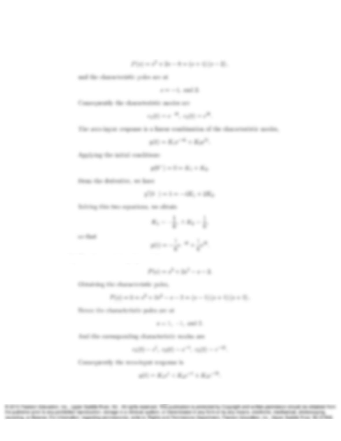
a) Clearly the characteristic polynomial of the system is
b) The characteristic polynomial is
20
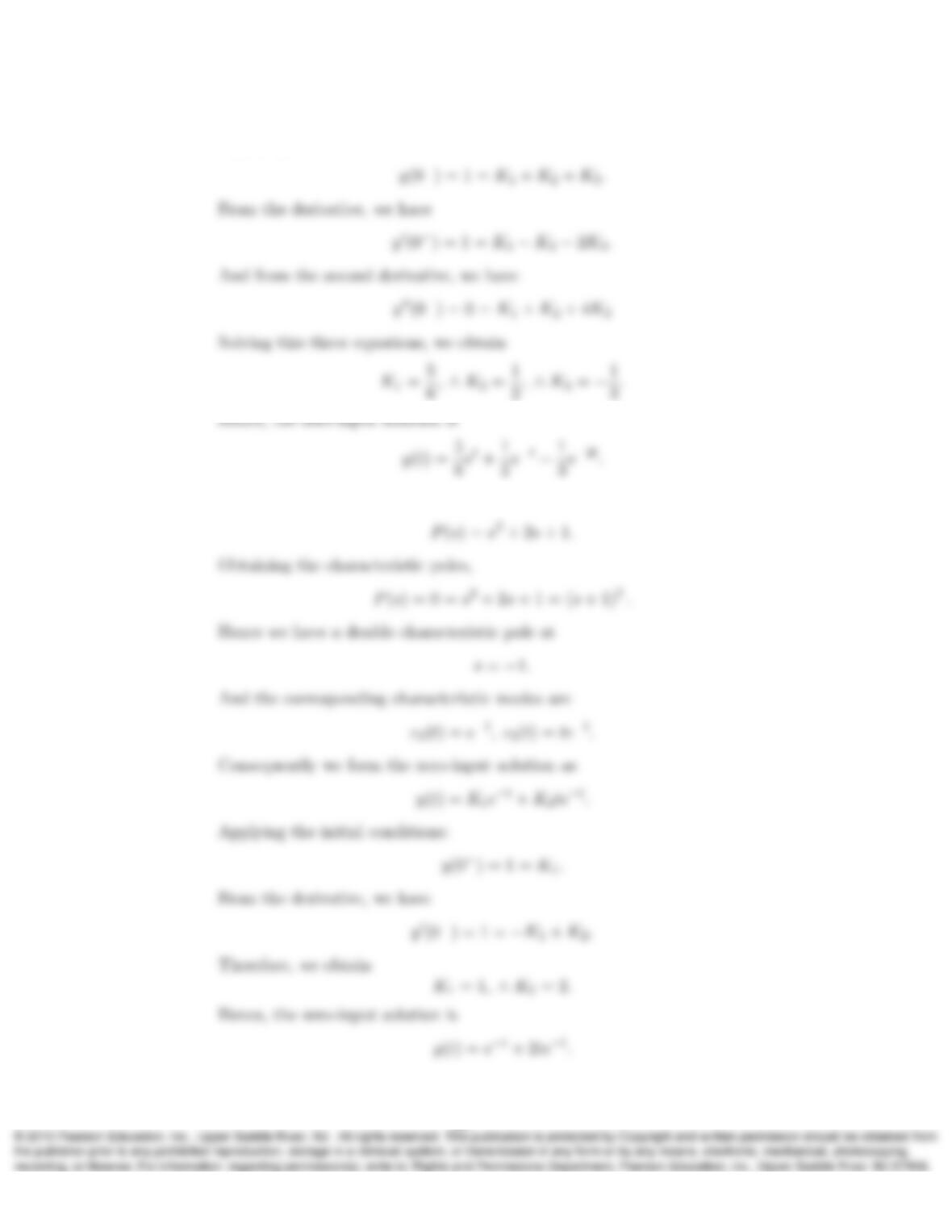
Applying the initial conditions:
c) The characteristic polynomial is
16.
21
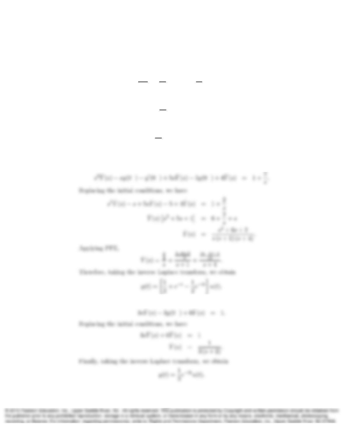
a) Take the Laplace transform of the following ODE to determine ˆ
Y(s)assuming
f(t) = u(t),y(0−) = 1, and y′(0−) = 0. Determine y(t)for t > 0by taking
the inverse Laplace transform of ˆ
Y(s).
d2y
dt2+ 5dy
dt + 4y(t) = df
dt + 2f(t).
b) Repeat (a) for y(0−) = 0 and
3dy
dt + 6y(t) = δ(t).
c) Repeat (a) for y(0−) = 0 and
dy
dt −y(t) = e−tu(t).
Solution:
a) Taking the Laplace transform gives
b) Taking the Laplace transform gives
22
c) Taking the Laplace transform, we obtain
17. The transfer function of a particular LTIC system is ˆ
H(s) = ˆ
Y(s)
ˆ
F(s)=4
s−2. Is the
system asymptotically stable? Explain. Is the system BIBO stable? Explain.
Solution:
18. What are the resonance frequencies in a system with the transfer function
ˆ
H(s) = s
(s+ 1)(s2+ 4)(s2+ 25)?
Is the system marginally stable? BIBO-stable? Explain.
Solution:
19. Determine the zero-state response y(t) = h(t)∗f(t)of the marginally stable system
ˆ
H(s) = 1
(s2+ 4)(s2+ 9)
to an input f(t) = cos(2t)u(t).
Solution:
23
Then the output is
20. a) Determine the transfer function and characteristic modes of the circuit shown
below assuming that Ca=Cb= 1/2F, R= 1.5 Ω, and L= 1/2H.
+
–
f(t)
y(t)
Ca
Cb
L
R
i(t)
v(t)
b) Given that v(0−) = 1 V and i(0−) = 0.5A,and using the element values given
in part (a), determine y(t)for t > 0in the circuit:
f(t) = 0
y(t)
Ca
Cb
L
R
i(t)
v(t)
Solution:
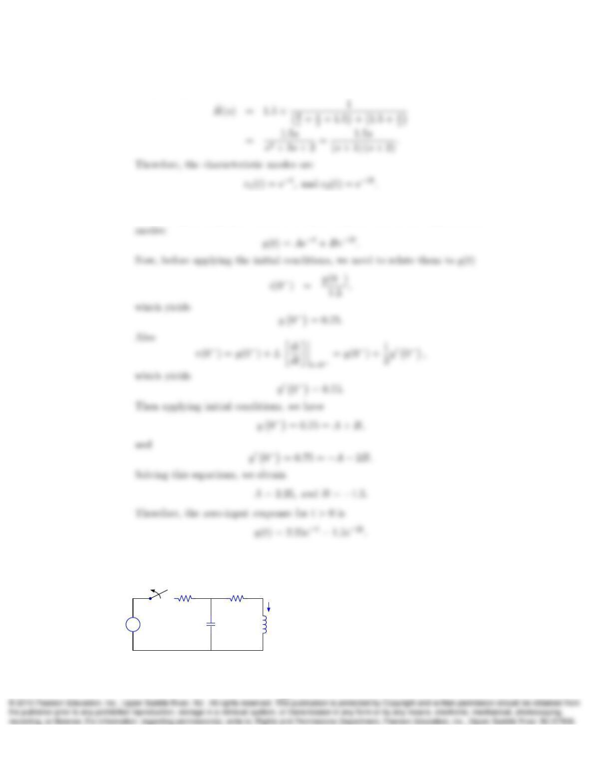
a) The equivalent circuit in the s-domain is
24
Simplifying, we obtain
b) We already have the zero-state transfer function. Now we want to calculate
the zero-input response, which is a linear combination of the characteristic
21. Consider the following circuit, which is in DC steady-state until the switch is opened
at t= 0,
+
–
t= 0
4V 1F 2H
2Ω 2Ω
v(t)
i(t)
+
–
25
a) Determine i(0−)and v(0−).
b) Determine the characteristic modes of the circuit to the right of the switch for
t > 0.
c) Determine i(t)for t > 0.
Solution:
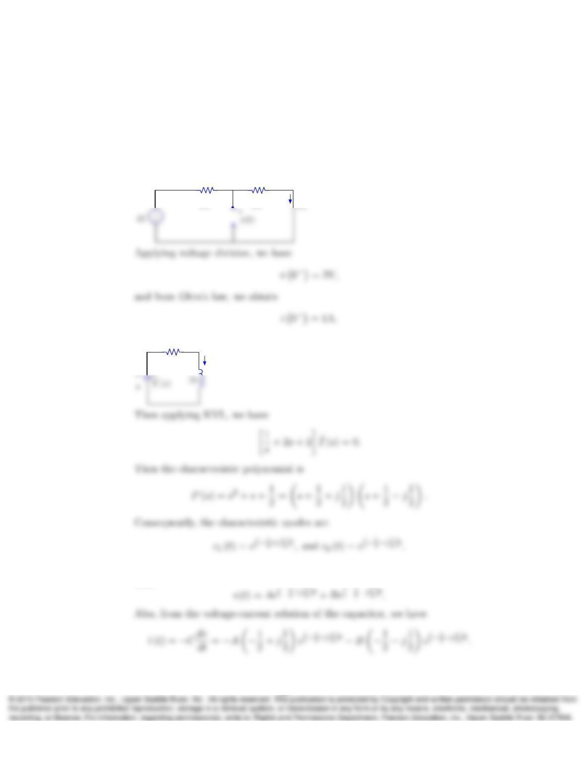
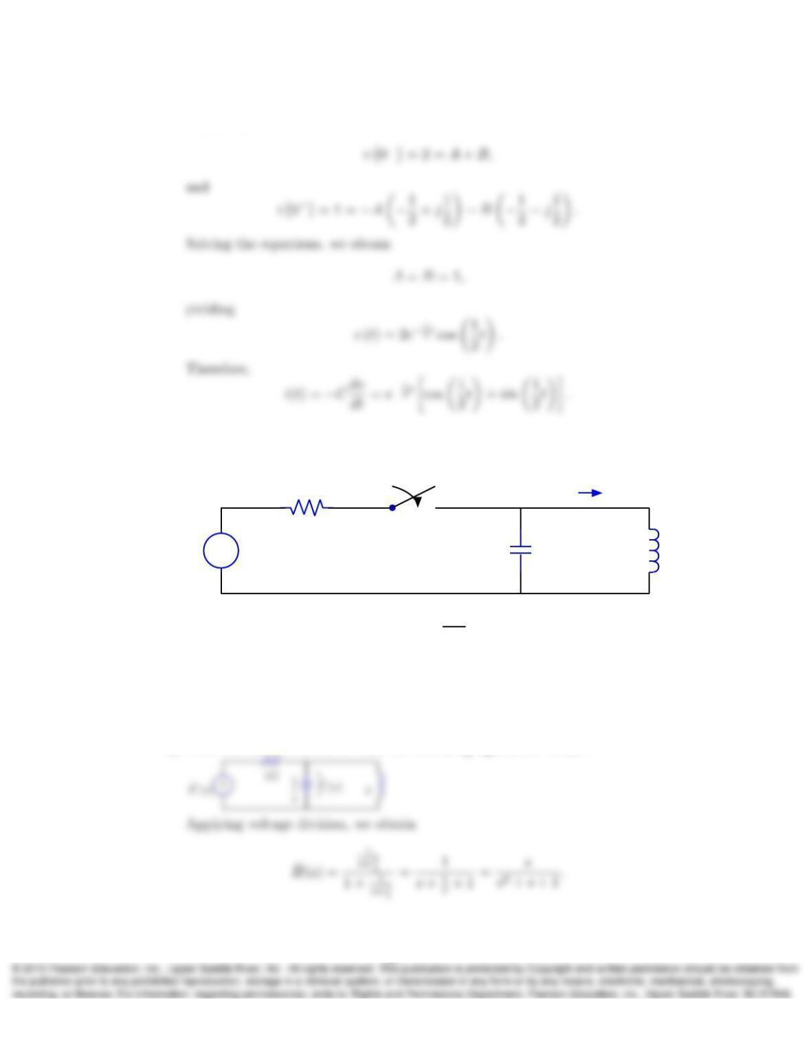
a) Before the switch opens, we have
2Ω 2Ω
i(t)
b) After the switch closes, we have
2Ω
ˆ
I(s)
c) The zero-input response is a linear combination of the characteristic modes,
then
26
Applying initial conditions, we have
22. In the circuit:
+
–
t= 0
1H
f(t)y(t)
+
–
1Ω
1F
i(t)
a) Determine the transfer function ˆ
H(s) = ˆ
Y(s)
ˆ
F(s)for t > 0.
b) Determine the zero-state response for t > 0if f(t) = e3t.
c) Determine the zero-input response for t > 0if y(0−) = 1 V and i(0−) = 0.
Solution:
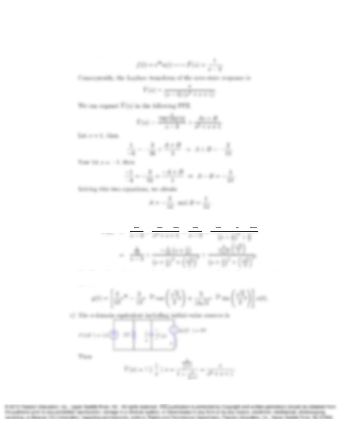
a) After the switch closes, we have the following equivalent circuit:
27
b) We are given the causal input
Hence, we have
ˆ
3
13
13 s+1
13
3
13
13 s+1
2+5/2
13
Finally, taking the inverse Laplace transform, we obtain the zero-state re-
sponse
s+s
28
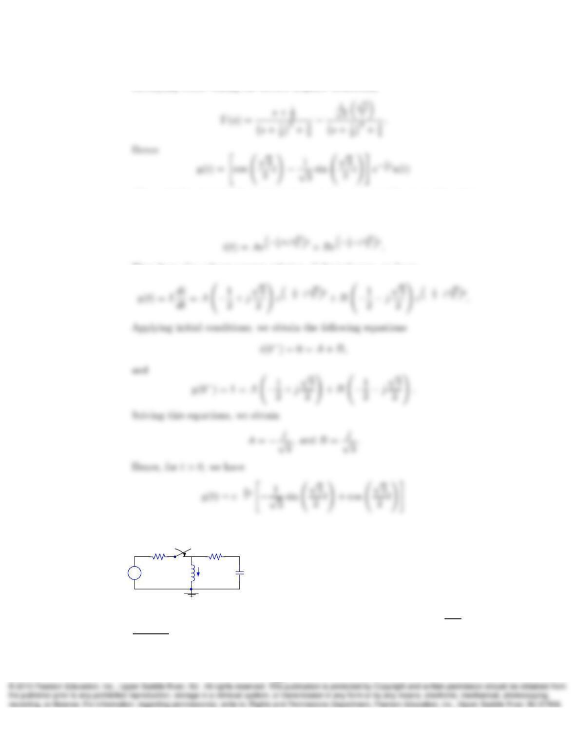
Modifying before taking the inverse Laplace transform,
Alternatively, we could form the zero-input response as a linear combination
of the characteristic modes. Since, for applying the initial conditions, we need
i(t), we can write
Then from the voltage-current relation of the inductor, we have
23. Consider the circuit:
+
–1H
f(t)
2Ω 1F
t= 0
2Ω
y(t)
+
–
i(t)
a) Show that the transfer function of the circuit for t > 0is ˆ
H(s) = ˆ
Y(s)
ˆ
F(s)=
s
4s2+5s+2 .
29
b) What are the characteristic modes of the circuit?
c) Determine y(t)for t > 0if f(t) = 1 V, y(0−) = 1 V, and i(0−) = 0.
Solution:
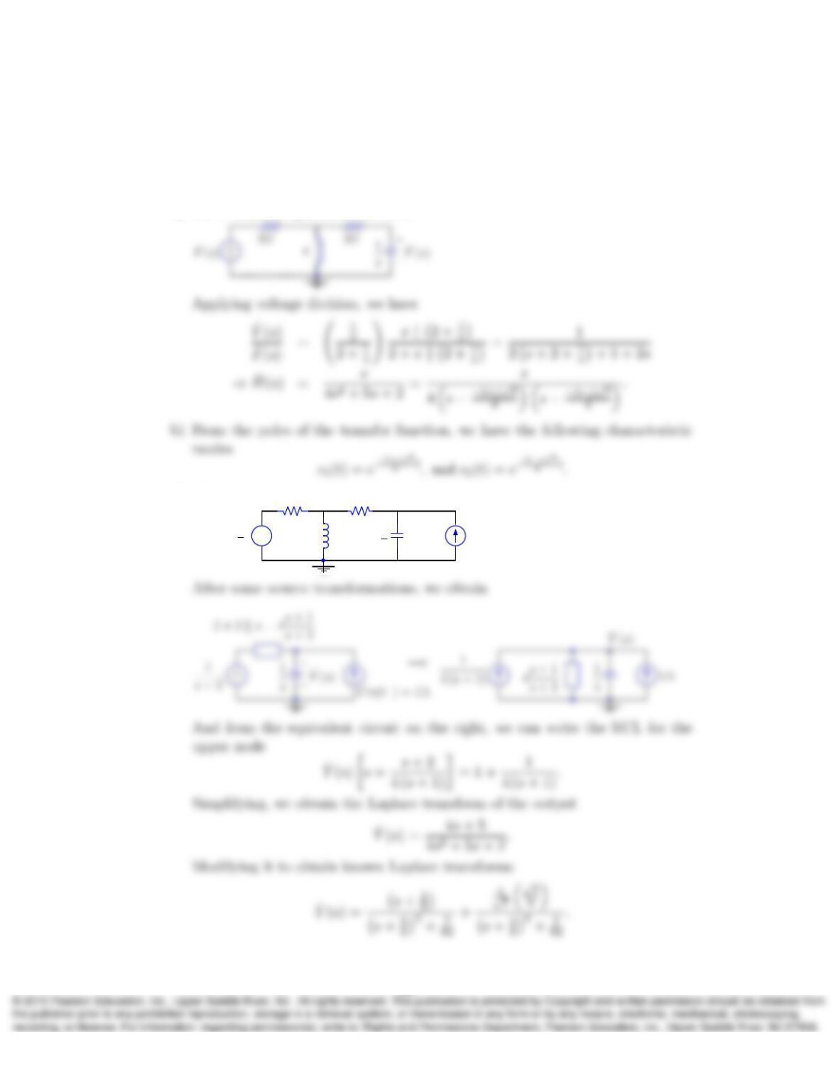
a) The s-domain equivalent circuit is
c) The s-domain equivalent including initial-value sources is
+
–s
ˆ
F(s) = 1
s
2Ω 1
s
2Ω ˆ
Y(s)
+
–Cv(0−) = 1A
30
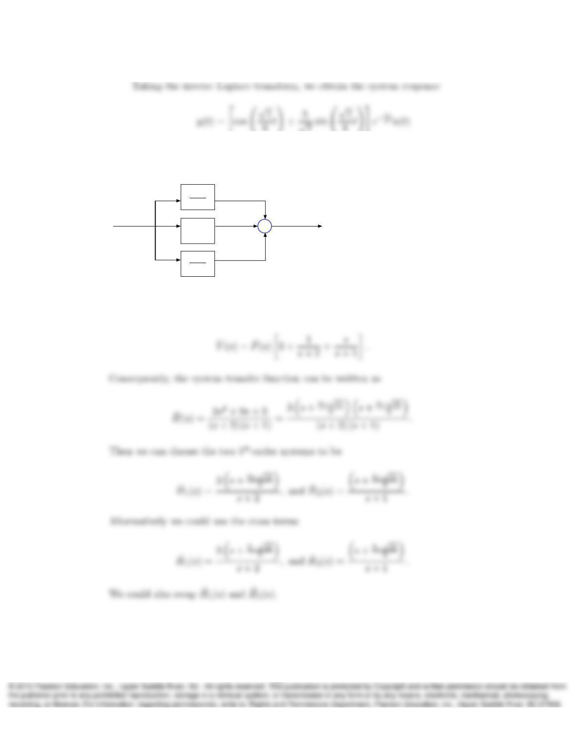
24. The system shown below can be implemented as a cascade of two 1st-order systems
ˆ
H1(s)and ˆ
H2(s). Identify the possible forms of ˆ
H1(s)and ˆ
H2(s).
Σ
ˆ
F(s)ˆ
Y(s)
1
s+ 2
2
s
s+ 1
Solution:
From the graph, we have
25. Determine the impulse response h(t)of the system shown below. Also determine
whether the system is BIBO stable.
31
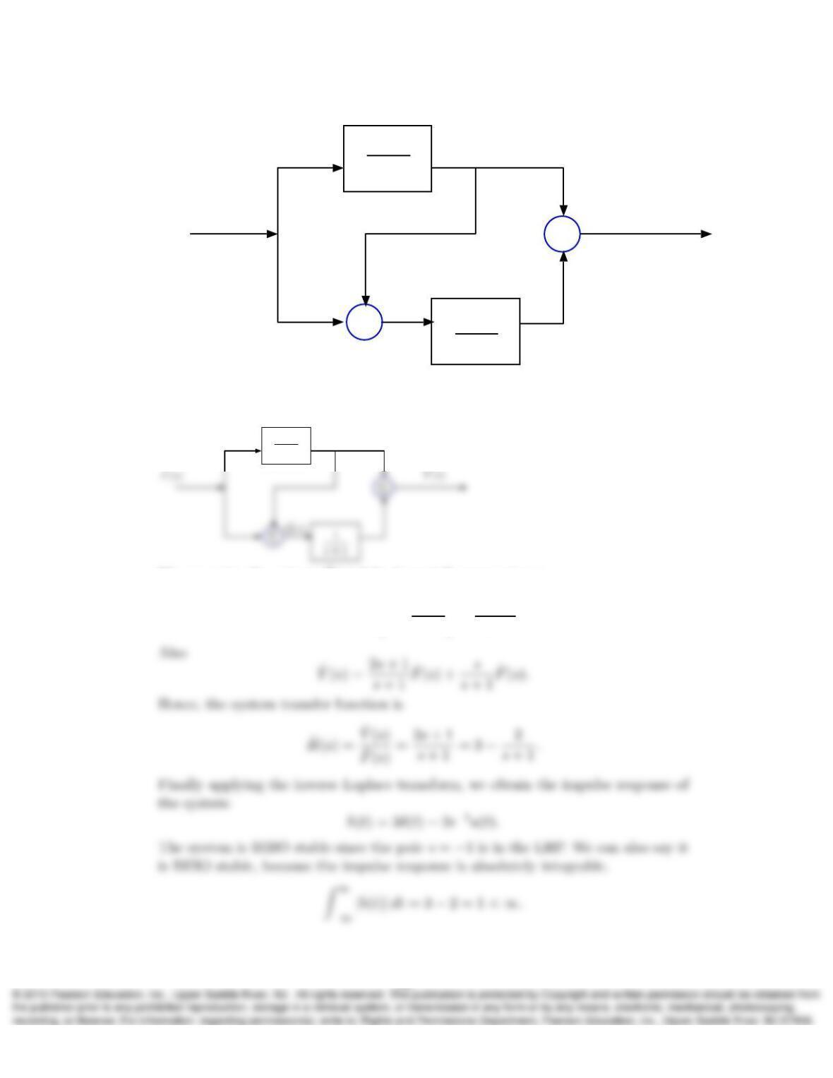
Σ
ˆ
F(s)ˆ
Y(s)
s
s+ 1
1
s+ 1
Σ
Solution:
Labeling the output of the summations
s
s+ 1
We can write the output ˆ
Q(s)of the lower-left summation as
ˆ
Q(s) = ˆ
F(s)1 + s
s+ 1=2s+ 1
s+ 1 ˆ
F(s).
32
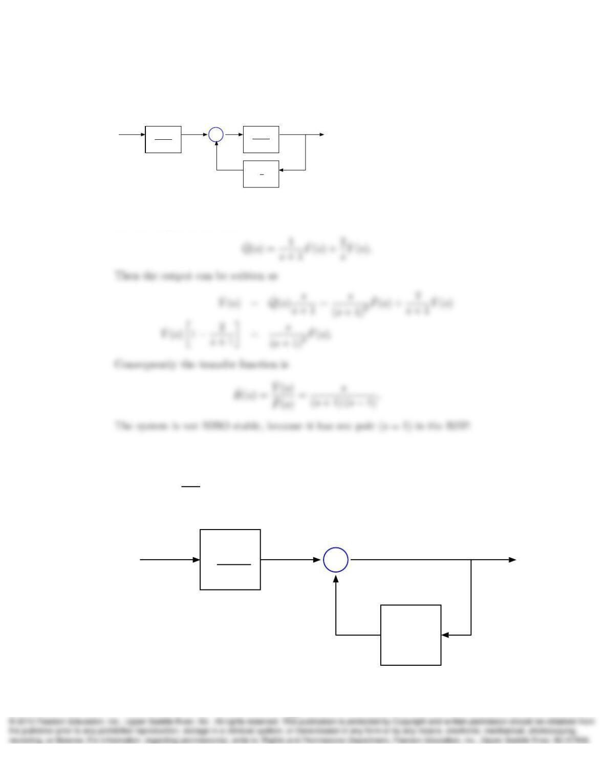
26. Determine the transfer function ˆ
H(s)of the system shown below. Also determine
whether the system is BIBO stable.
Σ
ˆ
F(s)ˆ
Y(s)
1
s+ 1
2
s
s
s+ 1
Solution:
Let the output of the sum be
27. Determine the transfer function ˆ
H(s)of the system shown below and determine
for which Kthe system is BIBO stable if
a) ˆ
Hf(s) = 1
s+K.
b) ˆ
Hf(s) = s+K.
Σ
Y(s)
1
s+ 1
Hf(s)
F(s)
33

Solution:
We can write the output as
ˆ
Y(s) = 1
s+ 1 ˆ
F(s) + ˆ
Hf(s)ˆ
Y(s)
ˆ
Y(s)h1−ˆ
Hf(s)i=1
s+ 1 ˆ
F(s).
Consequently, the general transfer function can be written as
b) For ˆ
Hf(s) = s+K, we have the following transfer function
ˆ
H(s) = 1
(s+ 1) (1 −s−K).
28. Consider a system with transfer function ˆ
H(s) = 2
s+1−j3.Draw a block diagram
that implements this transfer function. Individual blocks in the diagram may de-
note addition of real-valued signals, amplification by real values, and integration of
real-valued signals. Your diagram should contain no complex numbers. Hints: 1)
The transfer function ˆ
H(s) = a
s+bcorresponds in the time domain to the equation
dy
dt +by(t) = af (t)or, equivalently, y(t) = −bRy(τ)dτ +aRf(τ)dτ. So, it is easy
to draw a block diagram of this system. 2) In this homework exercise, you may
assume that f(t)is real-valued, but y(t)is complex-valued, which means that y(t)
34
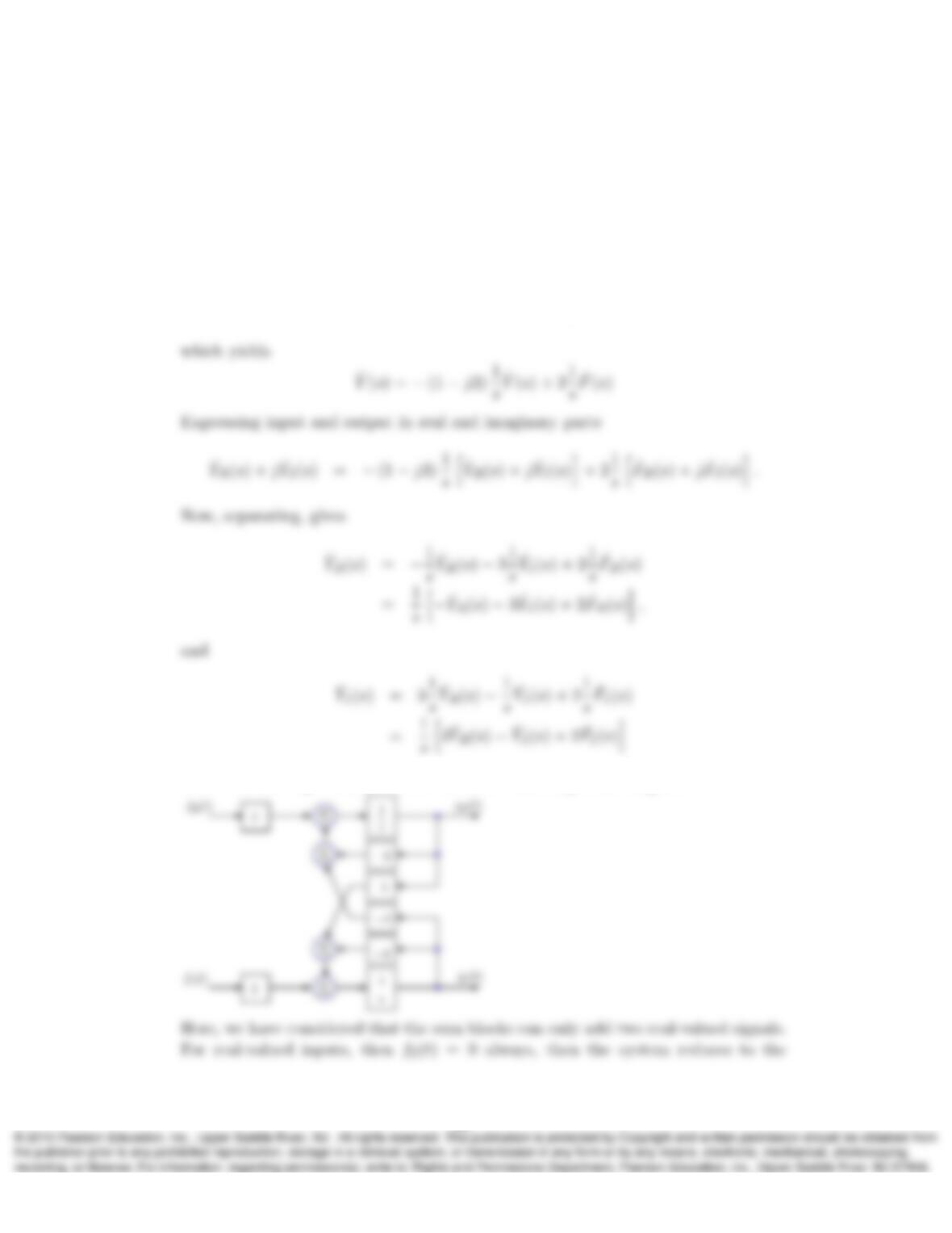
is a pair of real-valued signals. Your diagram will need to show yR(t)and yI(t),
the real and imaginary parts of y(t),separately. 3) Multiplication of a complex sig-
nal by a complex number involves four real multiplications. Addition of complex
signals requires two real additions.
Solution:
From the transfer function we can obtain the following relation
ˆ
Y(s) [s+ 1 −j3] = 2 ˆ
F(s),
With this two expressions, we can build the following block diagram
35
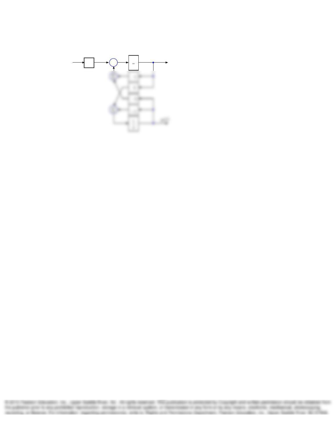
following diagram:
ΣyR(t)
fR(t)1
s
2
36