Chapter 11
1. Determine the Laplace transform ˆ
F(s), and the ROC, of the following signals f(t).
In each case identify the corresponding pole locations where |ˆ
F(s)|is not finite.
a) f(t) = u(t)−u(t−8)
b) f(t) = u(t)−u(t+ 8)
c) f(t) = u(t+ 8)
d) f(t) = 6
e) f(t) = rect(t−4
2)
f) f(t) = rect(t+8
3)
g) f(t) = te2tu(t)
h) f(t) = te2tu(t−2)
i) f(t) = 2te2t
j) f(t) = te−4t+δ(t) + u(t−2)
k) f(t) = e2tcos(t)u(t).
Solution:
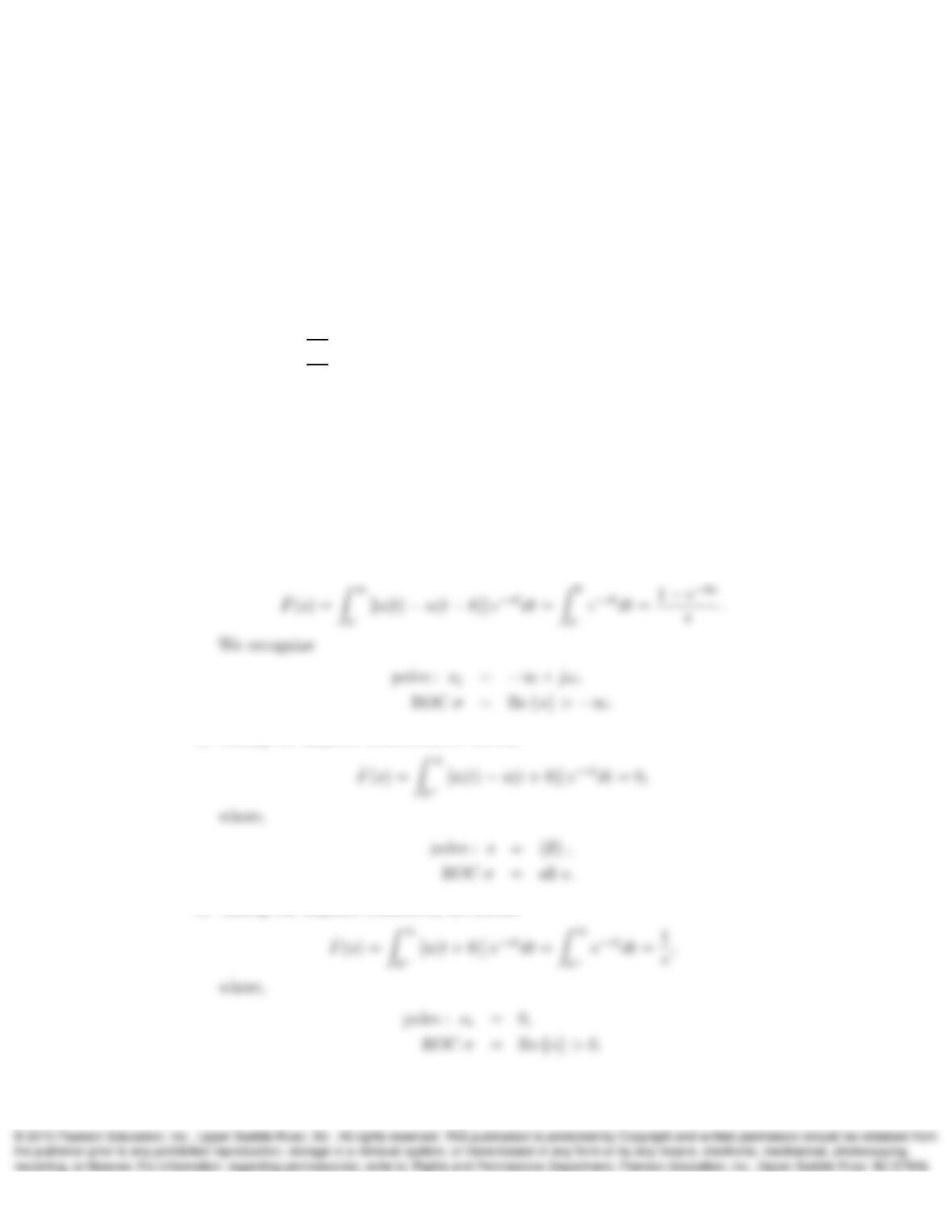
a) Using the Laplace transform definition, we have
b) Taking the Laplace transform, we obtain
c) Taking the Laplace transform, we obtain
1
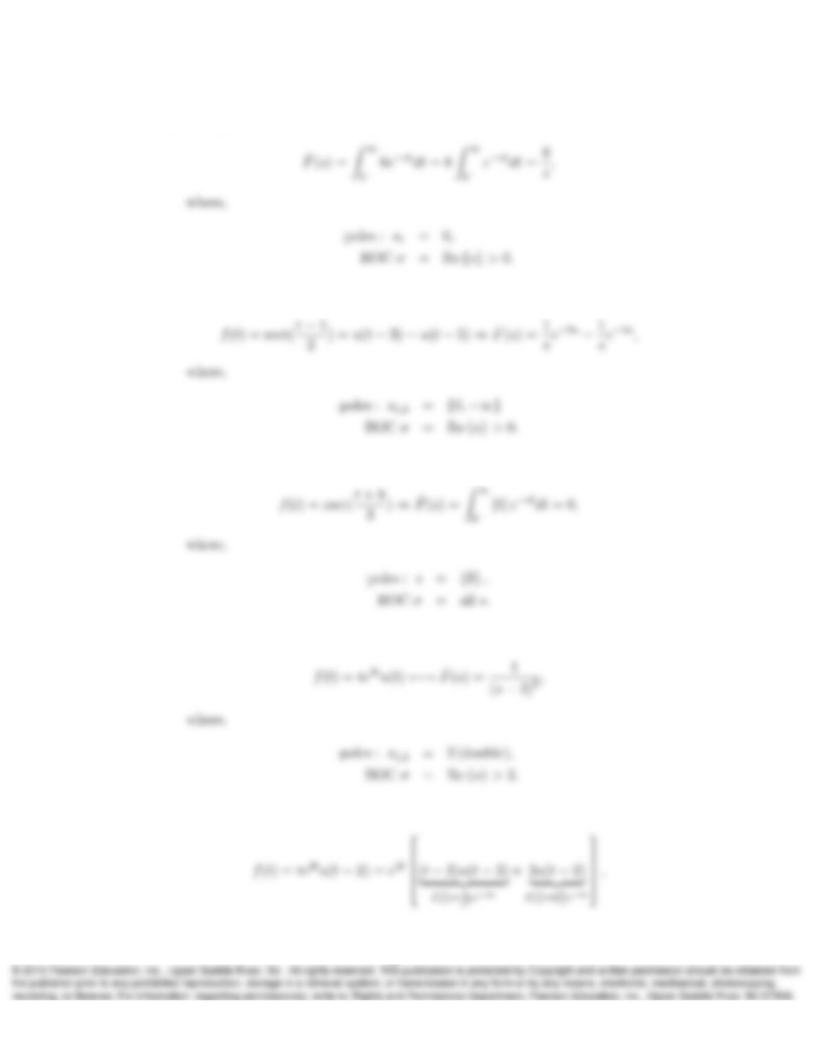
d) Taking the Laplace transform, we obtain
e) Using table 11.1 and Table 11.2 , we obtain
f) Taking the Laplace transform, we obtain
g) Using table 11.1 and Table 11.2 , we obtain
h) We first modify f(t)to resemble the items in the Laplace transform tables,
2
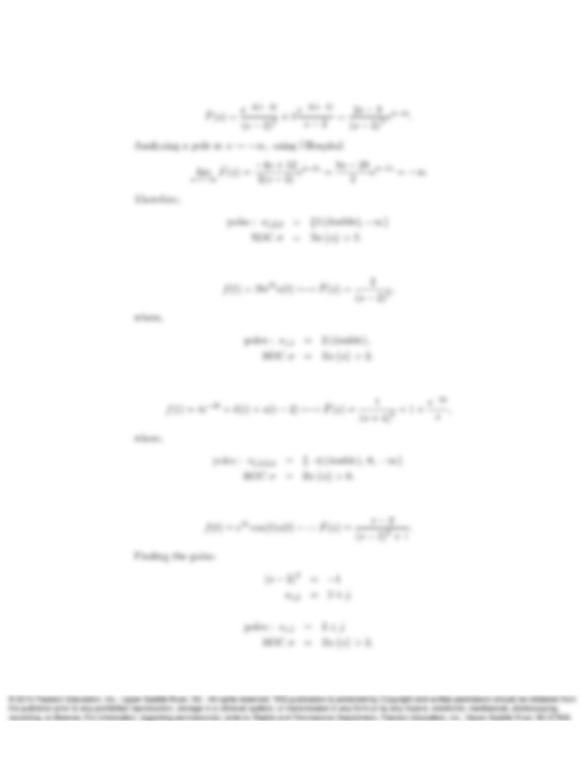
Now , using table 11.1 and Table 11.2 , we obtain
i) Since the Laplace transform starts at 0−, we have
j) Using table 11.1 and Table 11.2 , we obtain
k) Using table 11.1 , we obtain
3
2. For each of the following Laplace transforms ˆ
F(s),determine the inverse Laplace
transform f(t).
a) ˆ
F(s) = s+3
(s+2)(s+4)
b) ˆ
F(s) = s2
(s+2)(s+4)
c) ˆ
F(s) = 1
s(s−5)2
d) ˆ
F(s) = s2+2s+1
(s+1)(s+2)
e) ˆ
F(s) = s
s2+2s+5
f) ˆ
F(s) = s3
s2+4 .
Solution:
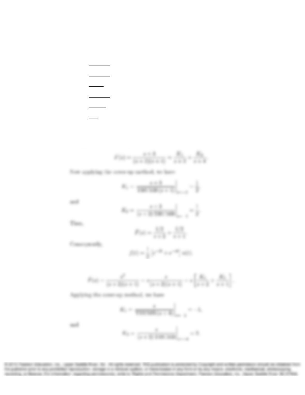
a) Using partial fraction expansion (PFE):
b) In this case we have an improper rational expression. Therefore,
4
c) Applying PFE,
Now trying s= 1 in the whole expression,
d) We first simplify the expression,
5
e) We first modify ˆ
F(s)to resemble the items in the Laplace transform tables,
ˆ
2
f) We first modify ˆ
F(s)to resemble the items in the Laplace transform tables,
ˆ
Consequently,
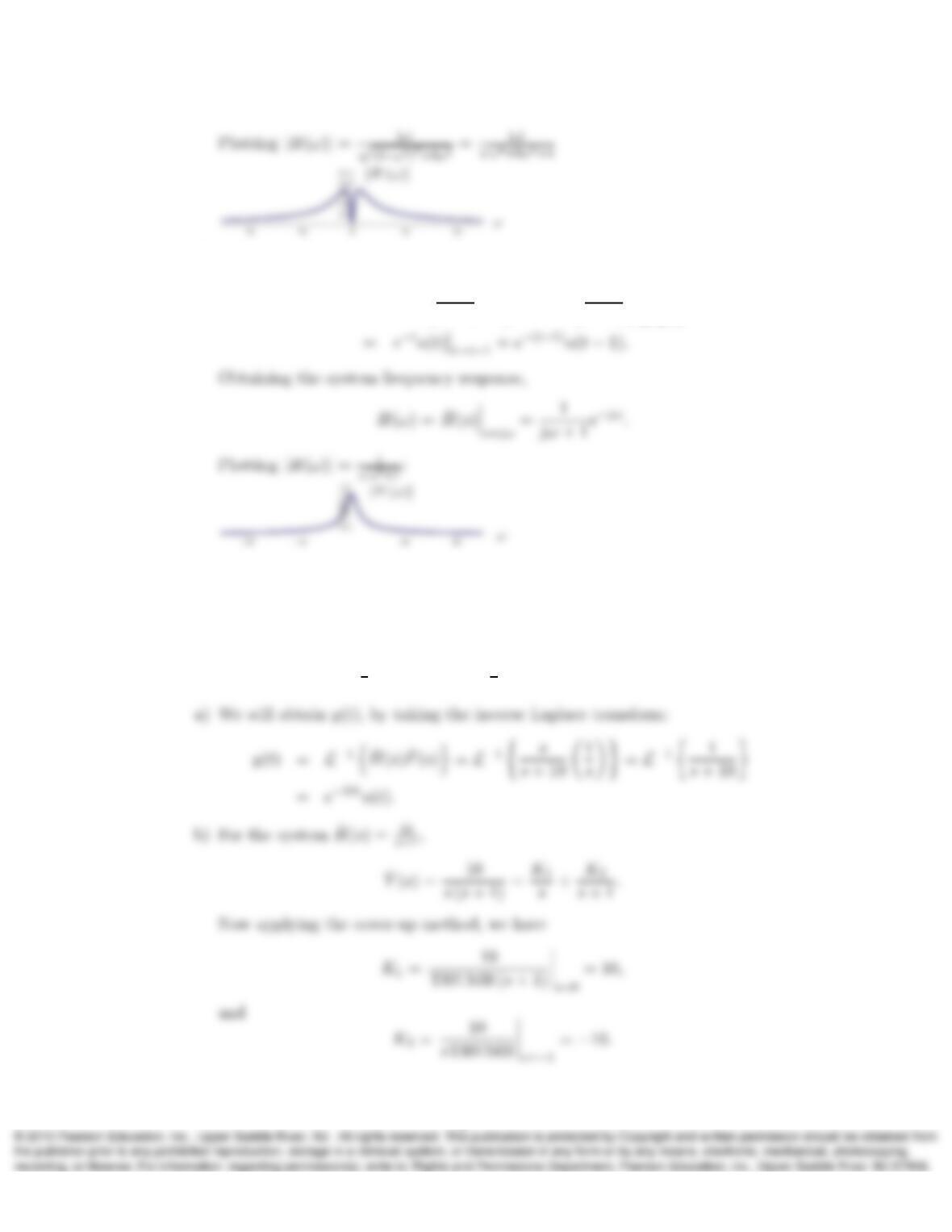
3. Sketch the amplitude response |H(ω)|and determine the impulse response h(t)of
the LTIC systems having the following transfer functions:
a) ˆ
H(s) = s
s+10
b) ˆ
H(s) = 10
s+1
c) ˆ
H(s) = s
s2+3s+2
d) ˆ
H(s) = 1
s+1 e−s.
Solution:
a) Taking the inverse Laplace transform
6
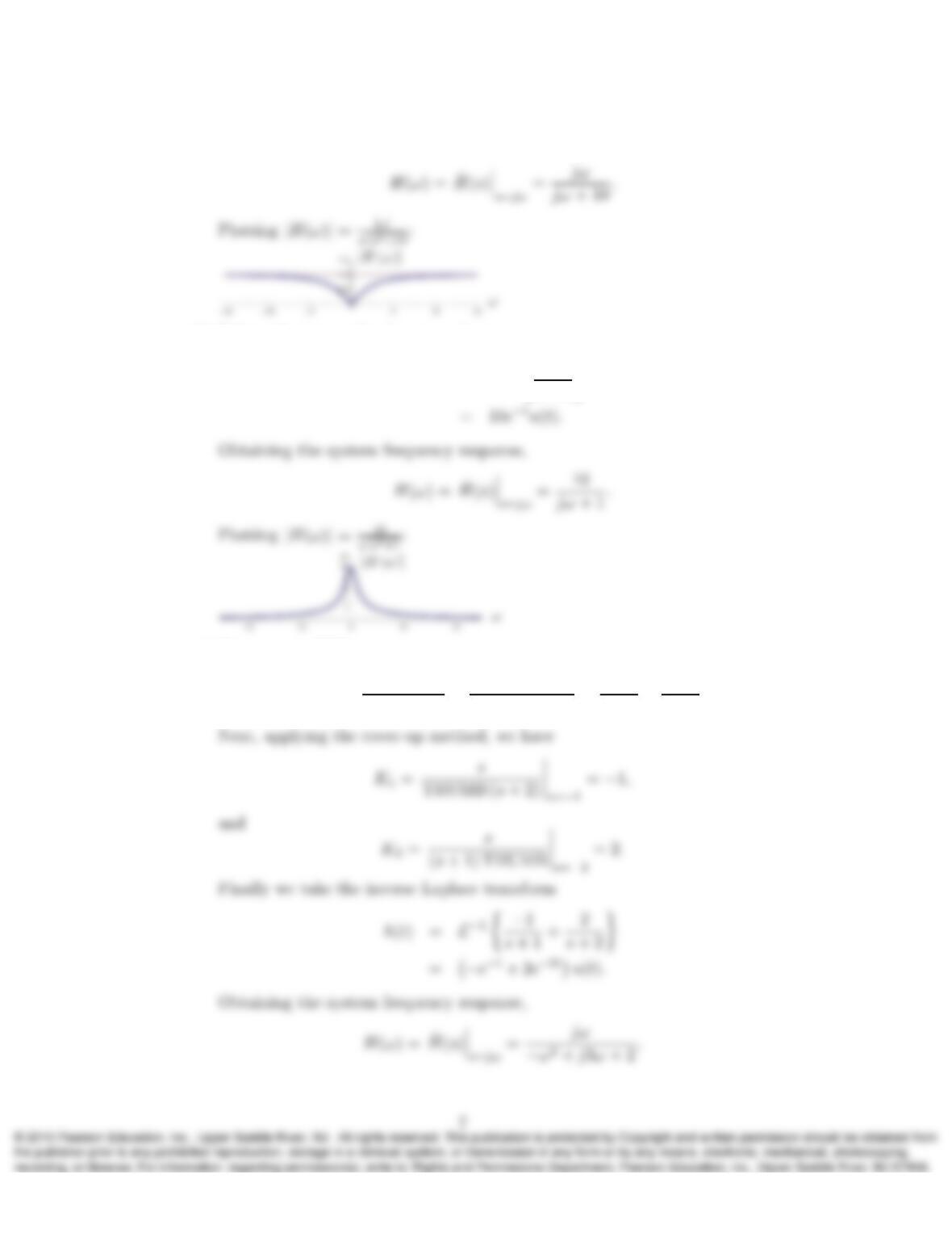
Obtaining the system frequency response,
b) Taking the inverse Laplace transform
h(t) = L−110
s+ 1
c) First we use PFE,
ˆ
H(ω) = s
s2+ 3s+ 2 =s
(s+ 1) (s+ 2) =K1
s+ 1 +K2
s+ 2.
d) Taking the inverse Laplace transform
h(t) = L−11
s+ 1e−s=L−11
s+ 1t→t−1
4. Determine the zero-state responses of the systems defined in Problem 11.3 to a
causal input f(t) = u(t). Use y(t) = h(t)∗f(t)or find the inverse Laplace transform
of ˆ
Y(s) = ˆ
H(s)ˆ
F(s), whichever is more convenient.
Solution:
We know that u(t)←→ 1
s. Hence ˆ
F(s) = 1
s.
8
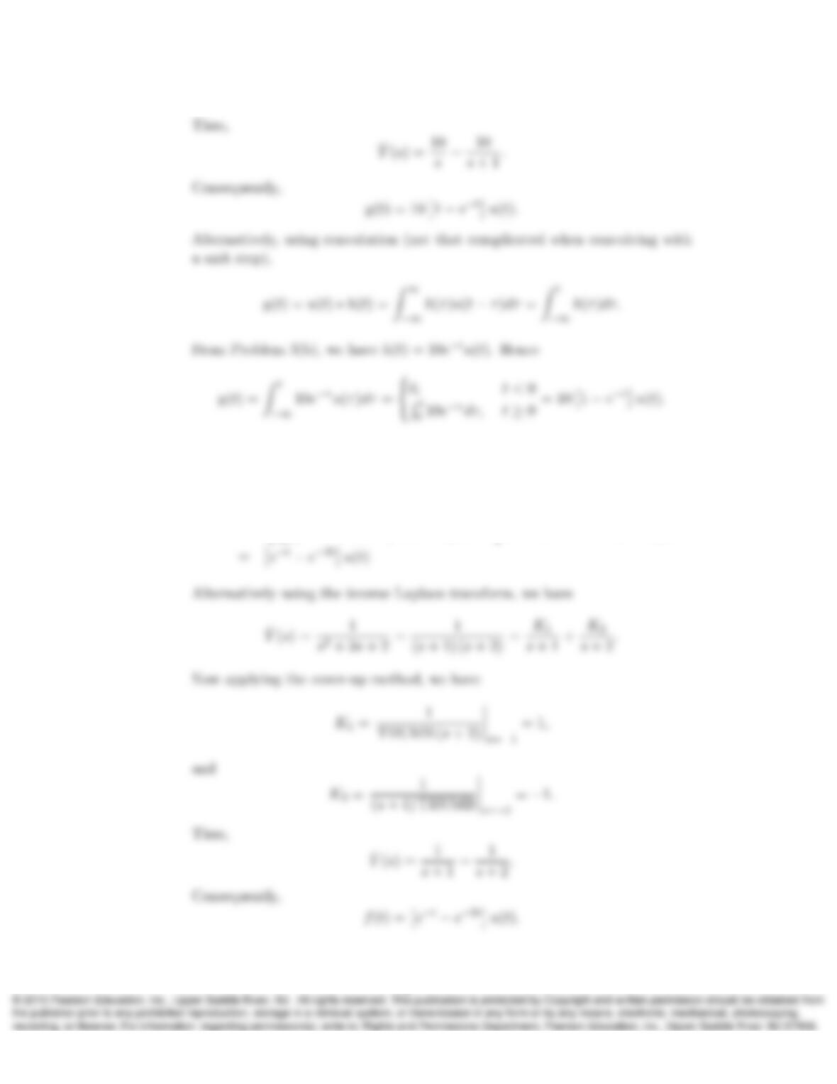
c) Similarly using convolution and from problem 3(c), we have h(t) = −e−t+ 2e−2tu(t).
Hence,
y(t) = (0, t < 0
Rt
0−e−τ+ 2e−2τdτ, t ≥0=(0, t < 0
e−t−1−e−2t+ 1, t ≥0.
9
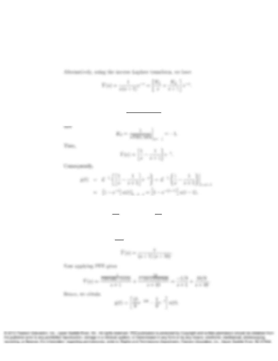
d) Using convolution, we have
y(t) = Zt
−∞
e−(τ−1)u(τ−1)dτ =(0, t < 1
Rt
1e−(τ−1)dτ, t ≥1=h1−e−(t−1)iu(t−1).
Now applying the cover-up method, we have
K1=1
THUMB (s+ 1)s=0
= 1,
5. Repeat Problem 4 with f(t) = e−tu(t).
We know that e−tu(t)←→ 1
s+1 . Hence ˆ
F(s) = 1
s+1 .
Solution:
We will solve this problem using the inverse Laplace transform.
a) For the system ˆ
H(s) = s
s+10 , we have
10
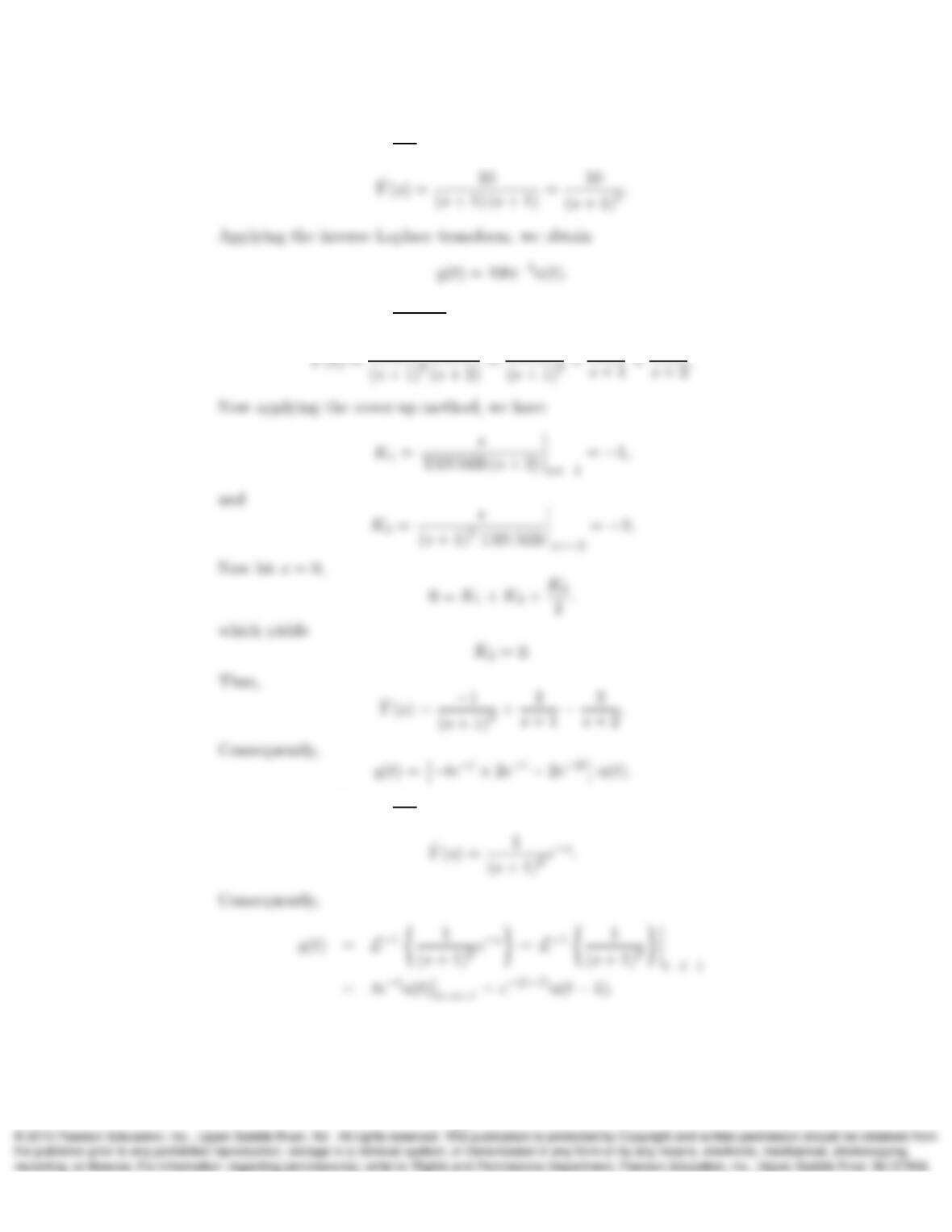
b) For the system ˆ
H(s) = 10
s+1 ,
c) For the system ˆ
H(s) = s
s2+3s+2 , we have
ˆ
d) For the system ˆ
H(s) = 1
s+1 e−s, we have
6. Given the frequency response H(ω), below, determine the system transfer function
ˆ
H(s)and impulse response h(t).
11
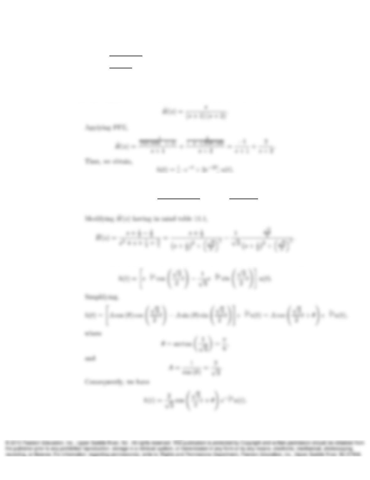
a) H(ω) = jω
(1+jω)(2+jω)
b) H(ω) = jω
1−ω2+jω .
Solution:
a) Replacing jω with s, we obtain the system transfer function,
b) Replacing jω with s, we obtain the system transfer function,
ˆ
H(s) = jω
1 + (jω)2+jω jω→s
=s
1 + s2+s.
Now using the Laplace transforms pairs 6 and 12 from table 11.1, we obtain
12
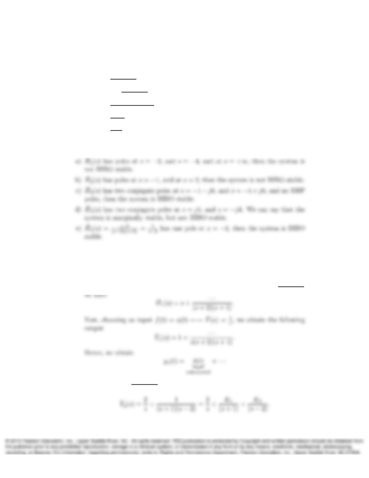
7. Determine whether the LTIC systems with the following transfer functions are
BIBO stable and explain why or why not.
a) ˆ
H1(s) = s3+1
(s+2)(s+4)
b) ˆ
H2(s) = 2 + s
(s+1)(s−2)
c) ˆ
H3(s) = s2+4s+6
(s+1+j6)(s+1−j6)
d) ˆ
H4(s) = 1
s2+16
e) ˆ
H5(s) = s−2
s2−4.
Solution:
8. For each unstable system in Problem 7 give an example of a bounded input that
causes an unbounded output.
Solution:
(a) First performing a long division operation to the improper ˆ
H1(s) == s3+1
(s+2)(s+4)
(b) For ˆ
H2(s) = 2 + s
(s+1)(s−2) , and using the unit step as input, we obtain
13
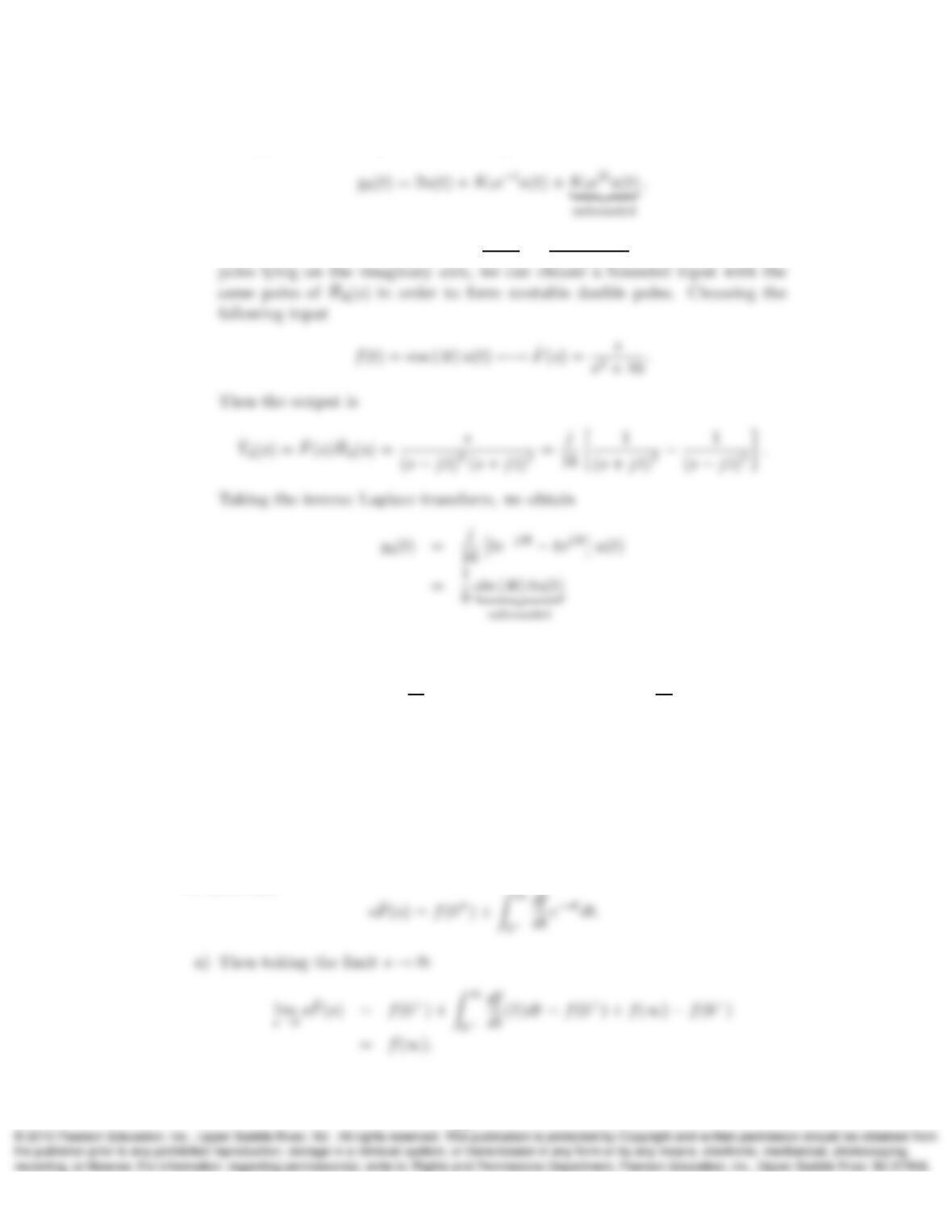
Taking the inverse Laplace transform gives
(d) For the marginally stable ˆ
H4(s) = 1
s2+16 =1
(s−j4)(s+j4) , with two conjugate
9. Given that
sˆ
F(s)−f(0−) = Z∞
0−
df
dt e−stdt =f(0+)−f(0−) + Z∞
0+
df
dt e−stdt,
and assuming that Laplace transforms of f(t)and f′(t)exist, show that
a) lims→0sˆ
F(s) = f(∞),
b) lims→∞ sˆ
F(s) = f(0+).
Solution:
We have that
14
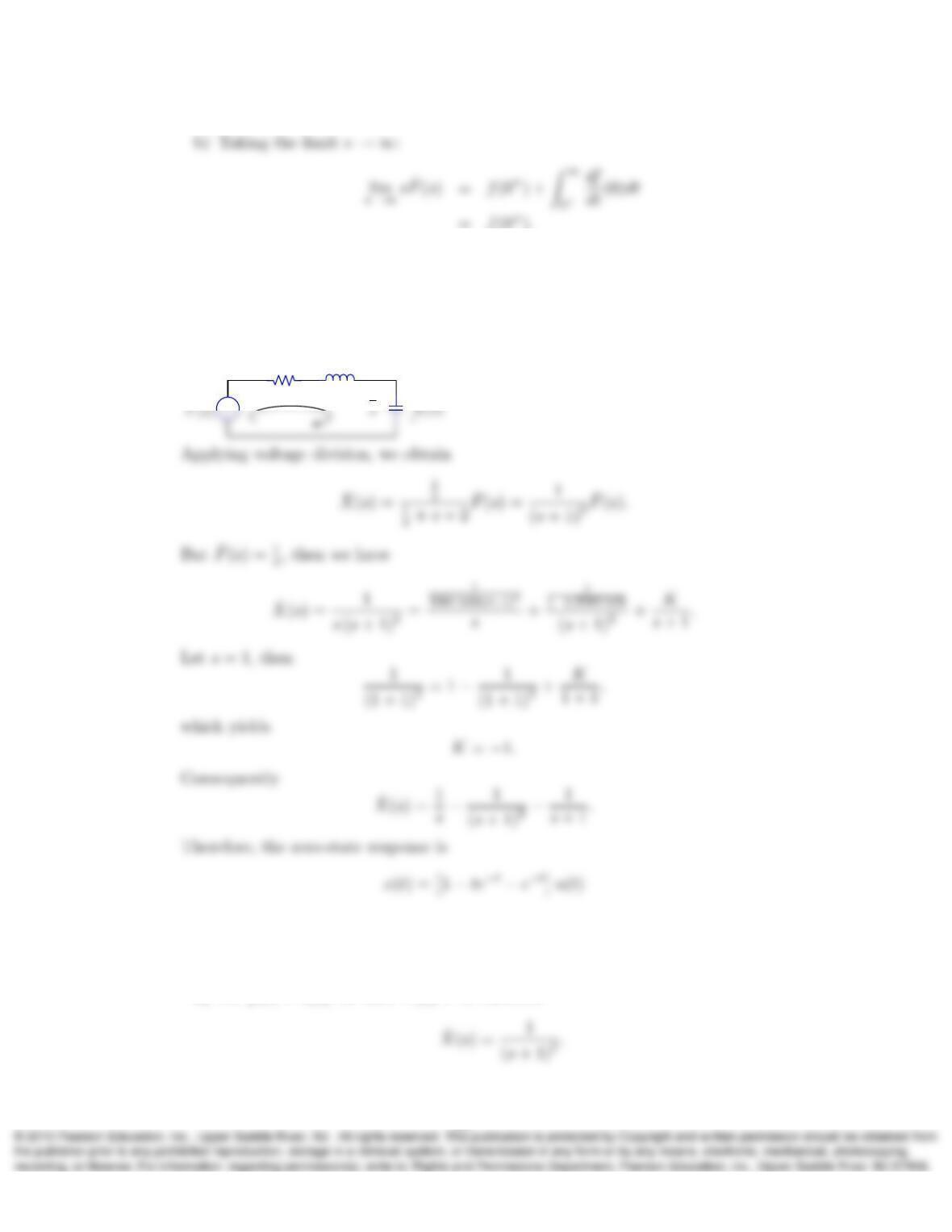
10. Consider the LTIC circuit shown in Figure 11.7a. What is the zero-state response
x(t)if the input is f(t) = u(t)? Hint: Use s-domain voltage division to relate ˆ
X(s)
to ˆ
F(s)in Figure 11.7b.
Solution:
From figure 11.7b we have
sΩ
+
2Ω 1
11. Repeat Problem 10 for (a) f(t) = δ(t), and (b) f(t) = tu(t).
Solution:
a) For f(t) = δ(t), we have ˆ
F(s) = 1, therefore
15
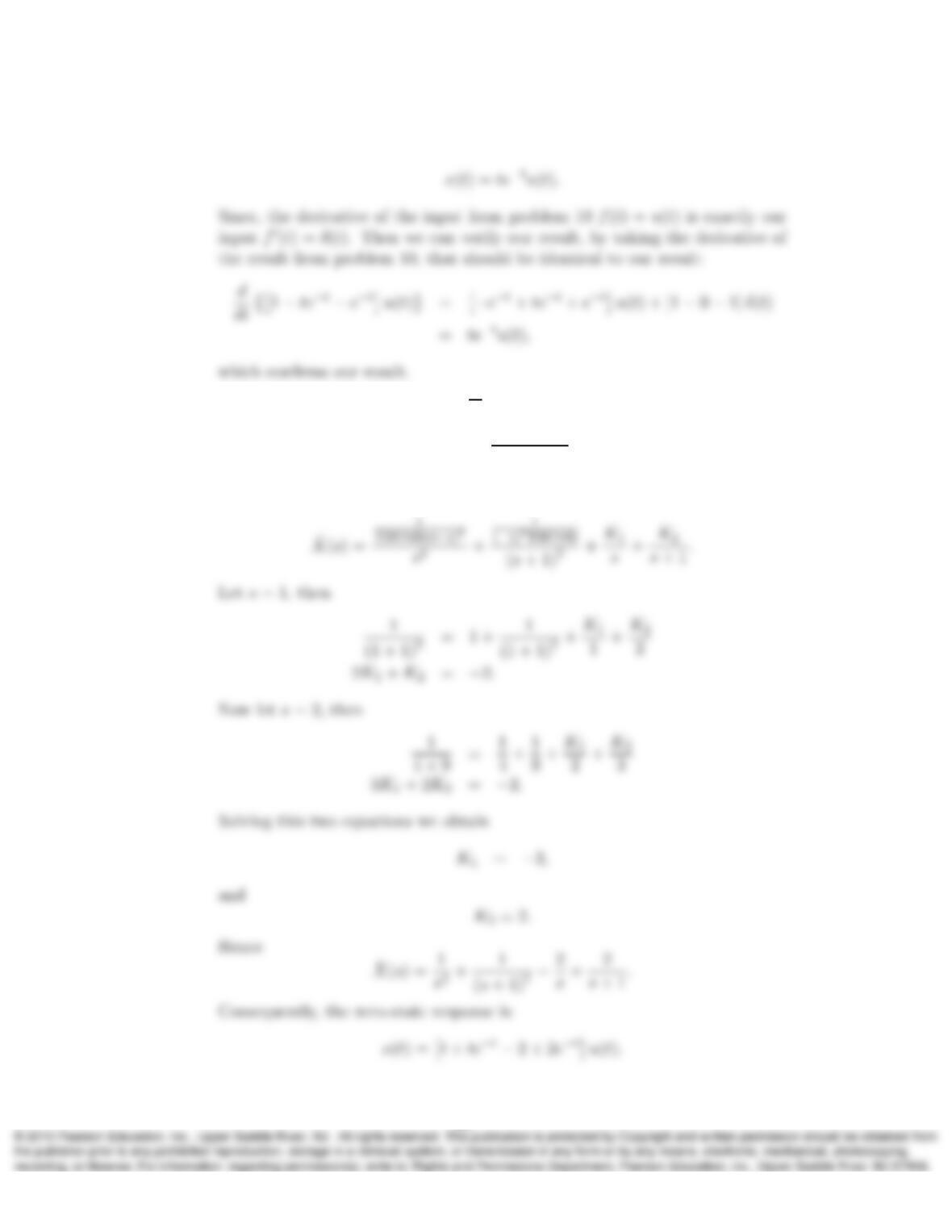
Consequently, the zero-state response is
b) For f(t) = tu(t), we have ˆ
F(s) = 1
s2, therefore
ˆ
X(s) = 1
s2(s+ 1)2.
Applying PFE we have
16
Since, the derivative of the input f(t) = tu(t)is exactly the input in problem
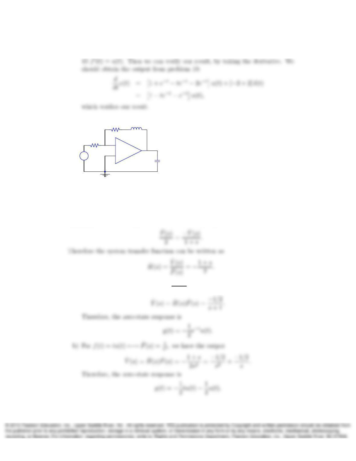
12. Consider the following circuit with C > 0:
+
–
f(t)+
–
y(t)
1H
2 Ω 1 Ω
C
a) Determine the zero-state response y(t)if f(t) = te−tu(t)
b) Determine the zero-state response y(t)if f(t) = tu(t).
Solution:
Applying KCL at the negative terminal of the op-amp:
a) For f(t) = te−tu(t)←→ ˆ
F(s) = 1
(s+1)2, we have the output
17
13. Determine the transfer functions ˆ
H(s)and the zero-state responses for LTIC sys-
tems described by the following ODEs:
a) d2y
dt2+ 3dy
dt + 2y(t) = e3tu(t)
b) d2y
dt2+y(t) = cos(2t)u(t)
c) d2y
dt2+y(t) = cos(t)u(t).
Solution:
a) Taking the Laplace transform with zero initial conditions, we obtain
b) Taking the Laplace transform with zero initial conditions, we obtain
18