Problems 9–41
12Ia+ (12 + j4)Ig+j20 5(j4) = 0.
P 9.63
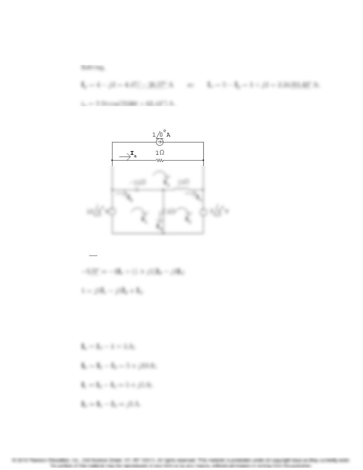
10/0= (1 j1)I11I2+j1I3;
Solving,
I1= 11 + j10 A; I2= 11 + j5 A; I3= 6 A;
9–42 CHAPTER 9. Sinusoidal Steady State Analysis
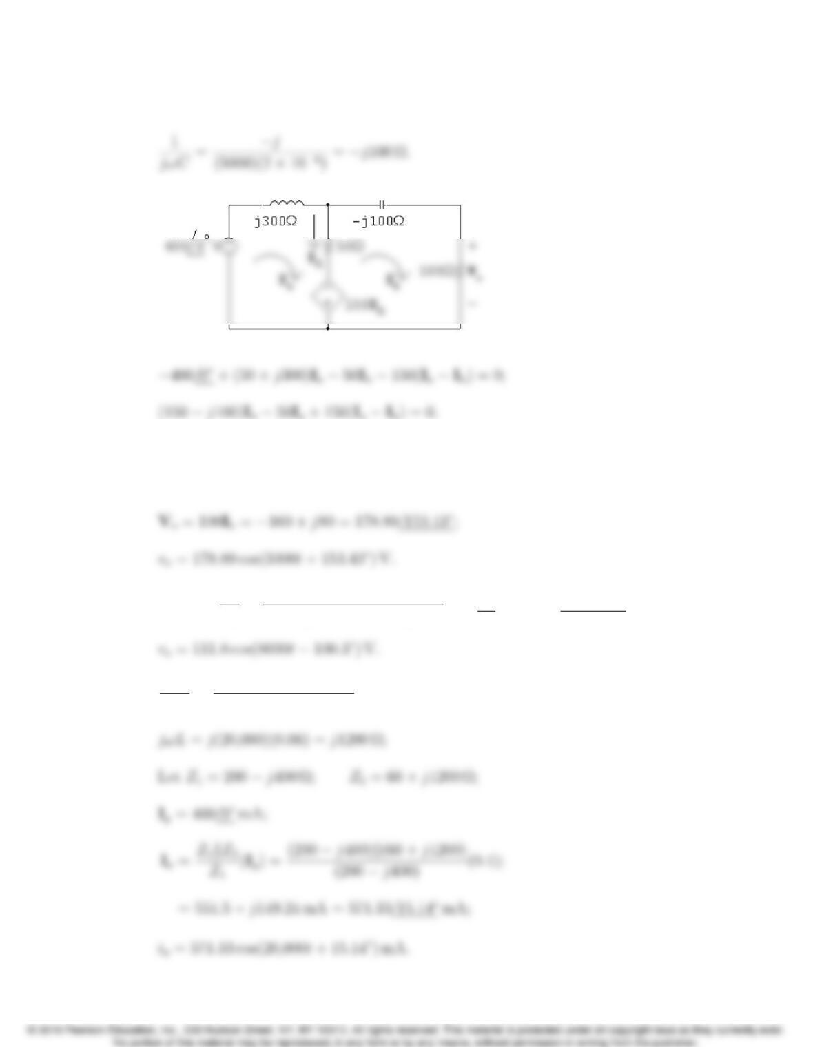
P 9.64 jωL=j5000(60 ⇥103)=j300 Ω;
Solving,
Ia=0.81.6 A; Ib=1.6+j0.8 A;
P 9.65 Vo=Vg
Zo
ZT
=500 j1000
300 + j1600 + 500 j1000(100/0) = 111.8/100.3V;
P 9.66 1
jωC=j
(20,000)(125 ⇥109)=j400 Ω;
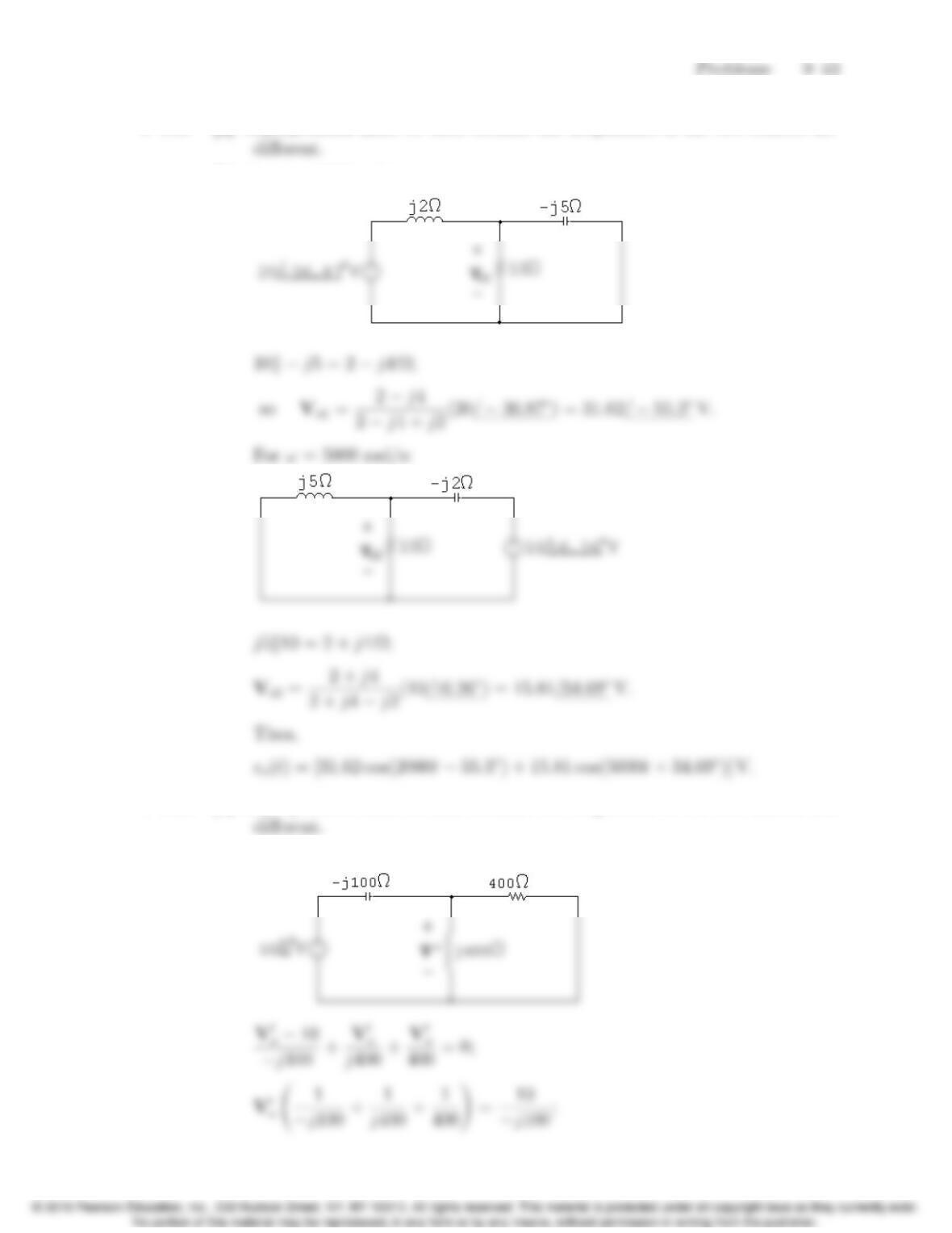
P 9.67 [a] Superposition must be used because the frequencies of the two sources are
[b] For ω= 2000 rad/s:
P 9.68 [a] Superposition must be used because the frequencies of the two sources are
[b] For ω= 16,000 rad/s:
9–44 CHAPTER 9. Sinusoidal Steady State Analysis
For ω= 4000 rad/s:
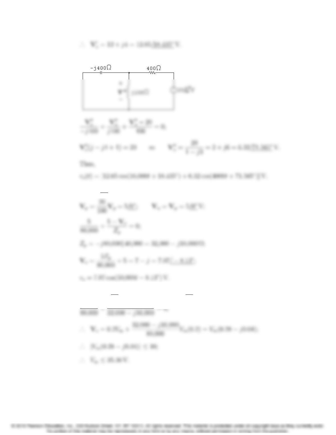
P 9.69 [a] Vg= 25/0V;
[b] Vp=0.2Vm/0;Vn=Vp=0.2Vm/0;
0.2Vm
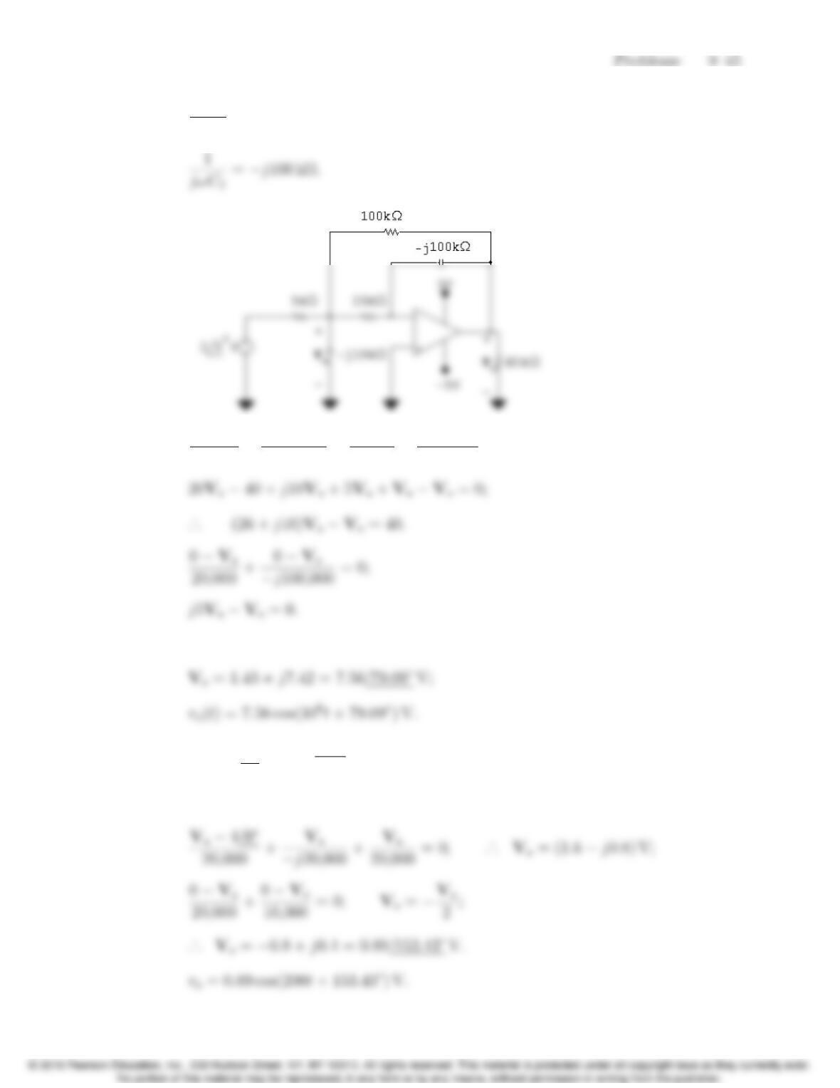
P 9.70 1
jωC1
=j10 kΩ;
Va2
5000 +Va
j10,000 +Va
20,000 +VaVo
100,000 = 0;
Solving,
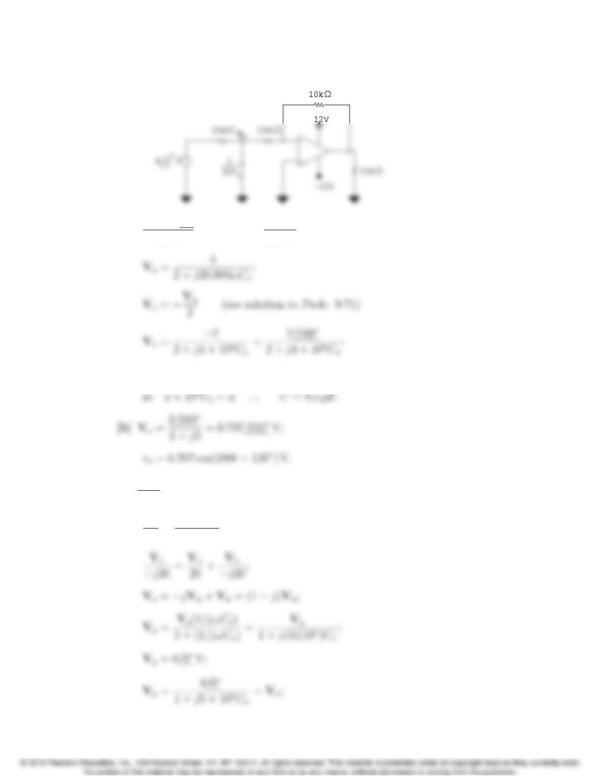
P 9.71 Vg=4
/0V; 1
jωC=j20 kΩ.
Let Va= voltage across the capacitor, positive at upper terminal.
Then:
9–46 CHAPTER 9. Sinusoidal Steady State Analysis
P 9.72 [a]
Va4/0
20,000 +jωCoVa+Va
20,000 = 0;
·
.. denominator angle = 45
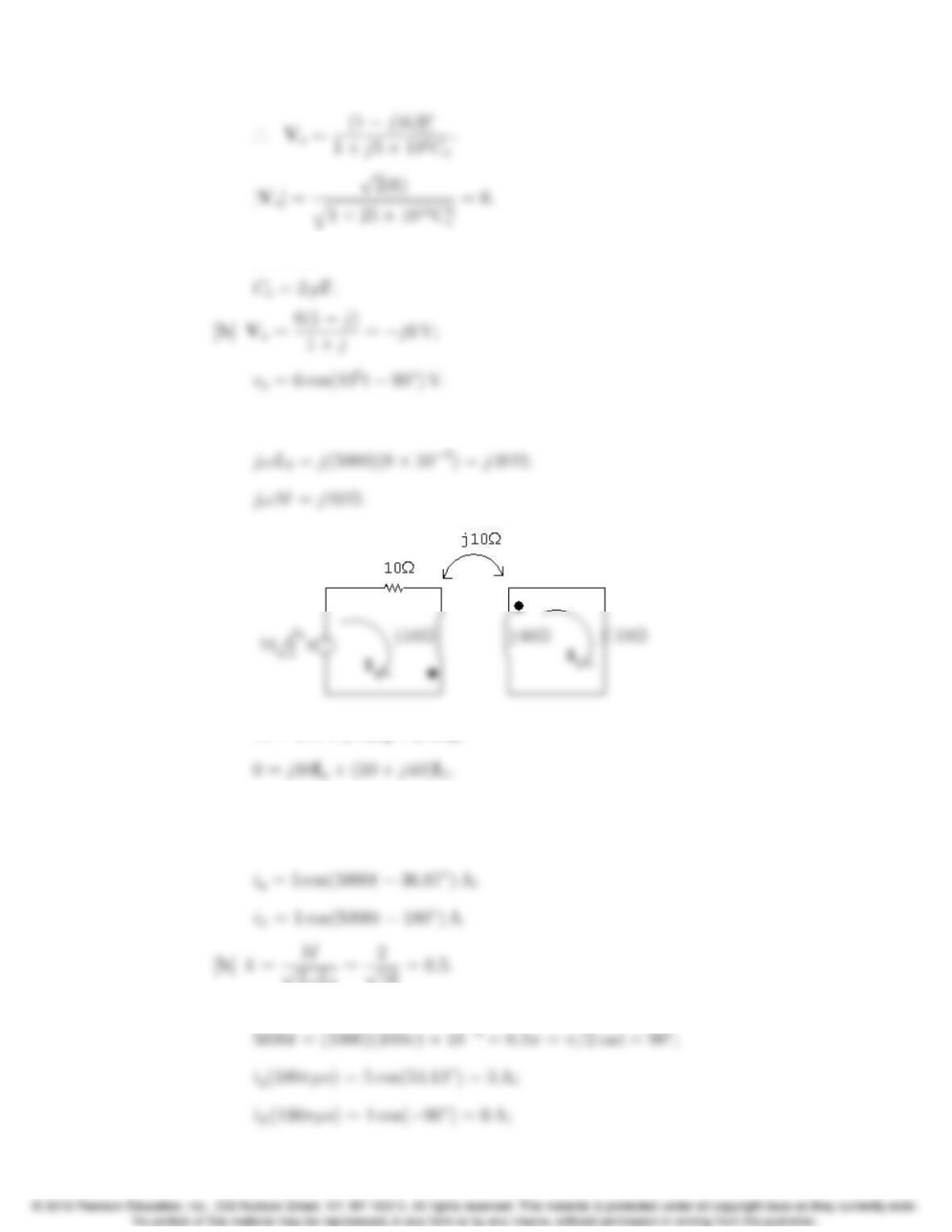
P 9.73 [a] 1
jωC=j20 Ω;
Vn
20 +VnVo
j20 = 0;
Problems 9–47
Solving,
P 9.74 [a] jωL1=j(5000)(2 ⇥103)=j10 Ω;
70 = (10 + j10)Ig+j10IL;
Solving,
Ig=4j3 A; IL=1 A;
[c] When t= 100πµs,
9–48 CHAPTER 9. Sinusoidal Steady State Analysis
w=1
2L1i2
1+1
2L2i2
2+Mi1i2=1
2(2 ⇥103)(9) + 0 + 0 = 9 mJ.
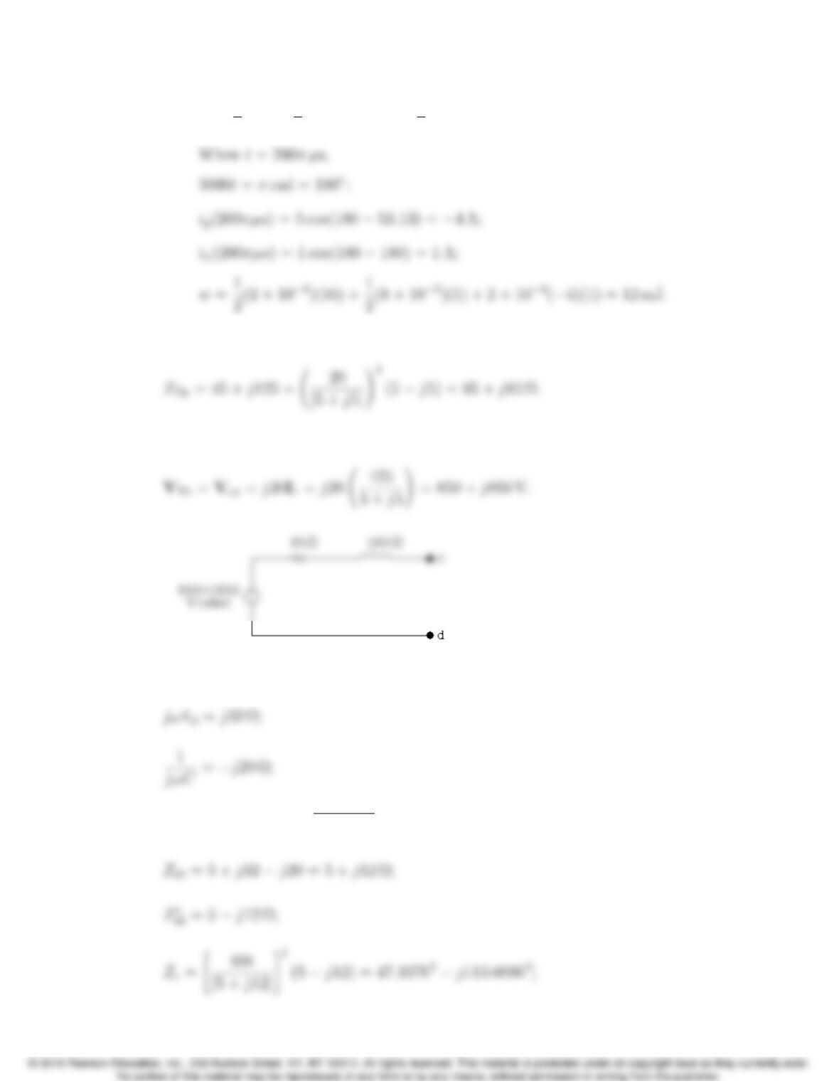
P 9.75 Remove the voltage source to find the equivalent impedance:
Using voltage division:
P 9.76 jωL1=j50 Ω;
jωM=j(4 ⇥103)kq(12.5)(8) ⇥103=j40kΩ;
Problems 9–49
Zab is resistive when
P 9.77 [a] jωL1=j(200 ⇥103)(103)=j200 Ω;
jωL2=j(200 ⇥103)(4 ⇥103)=j800 Ω;
M=kqL1L2=2k⇥103;
d|Zin|
[b] Zin (min) = 200 + 192(0.125) + j[200 0.125(256)]
9–50 CHAPTER 9. Sinusoidal Steady State Analysis
Note — You can test that the kvalue obtained from setting d|Zin|/dt =0
leads to a minimum by noting 0 k1. If k= 1,
P 9.78 [a] jωLL=j100 Ω
jωL2=j500 Ω
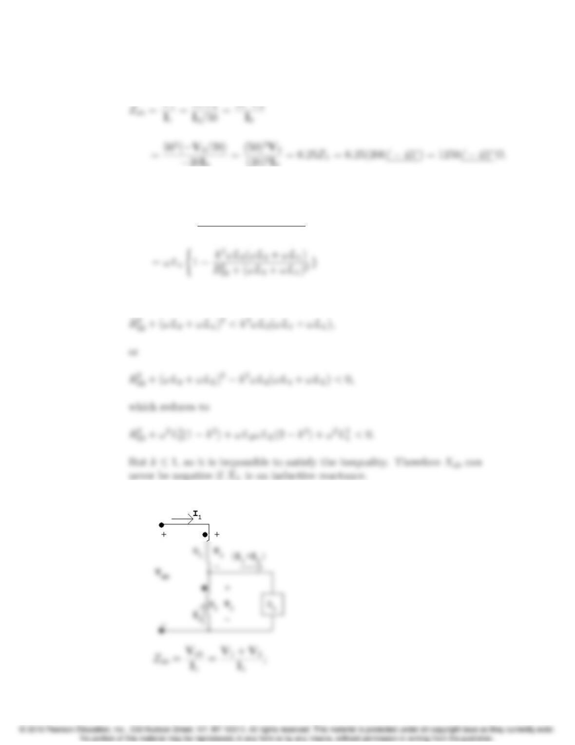
P 9.79
ZL=V3
I3
;
Problems 9–51
Substituting,
P 9.80 In Eq. 9.34 replace ω2M2with k2ω2L1L2and then write Xab as
Xab =ωL1k2ω2L1L2(ωL2+ωLL)
R2
22 +(ωL2+ωLL)2
For Xab to be negative requires
P 9.81 [a]
9–52 CHAPTER 9. Sinusoidal Steady State Analysis
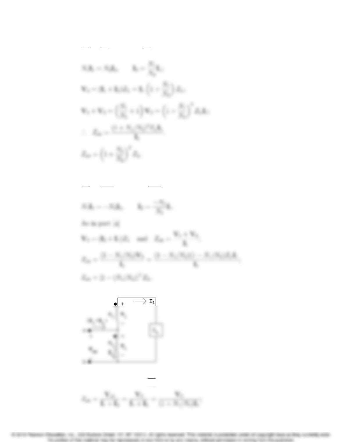
V1
N1
=V2
N2
,V2=N2
N1
V1;
[b] Assume dot on N2is moved to the lower terminal, then
V1
N1
=V2
N2
,V1=N1
N2
V2;
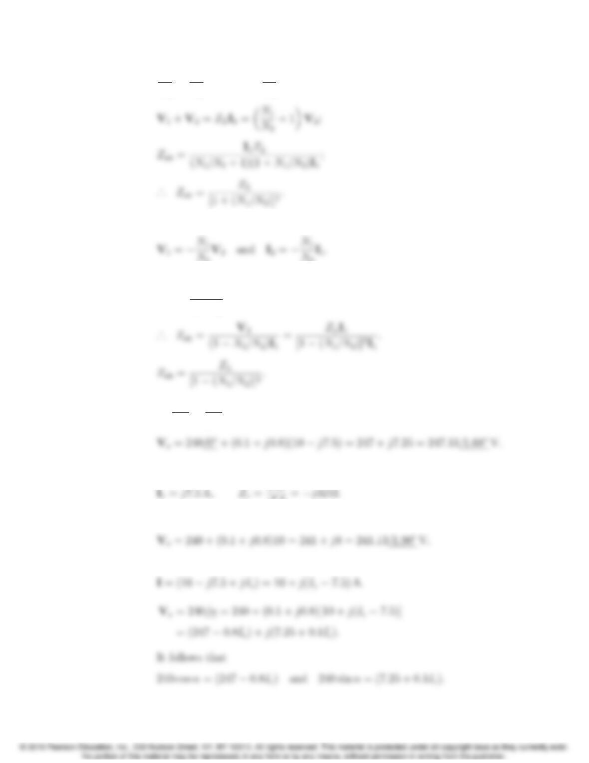
P 9.82 [a]
N1I1=N2I2,I2=N1
N2
I1;
Problems 9–53
V1
V2
=N1
N2
,V1=N1
N2
V2;
[b] Assume dot on the N2coil is moved to the lower terminal. Then
N2
N2
As before
Zab =V2
I1+I2
and V1+V2=ZLI1;
P 9.83 [a] I =240
24 +240
j32 = (10 j7.5) A;
[b] Use the capacitor to eliminate the jcomponent of I,therefore
j7.5=j32 Ω.
The capacitive reactance is 32 Ω.
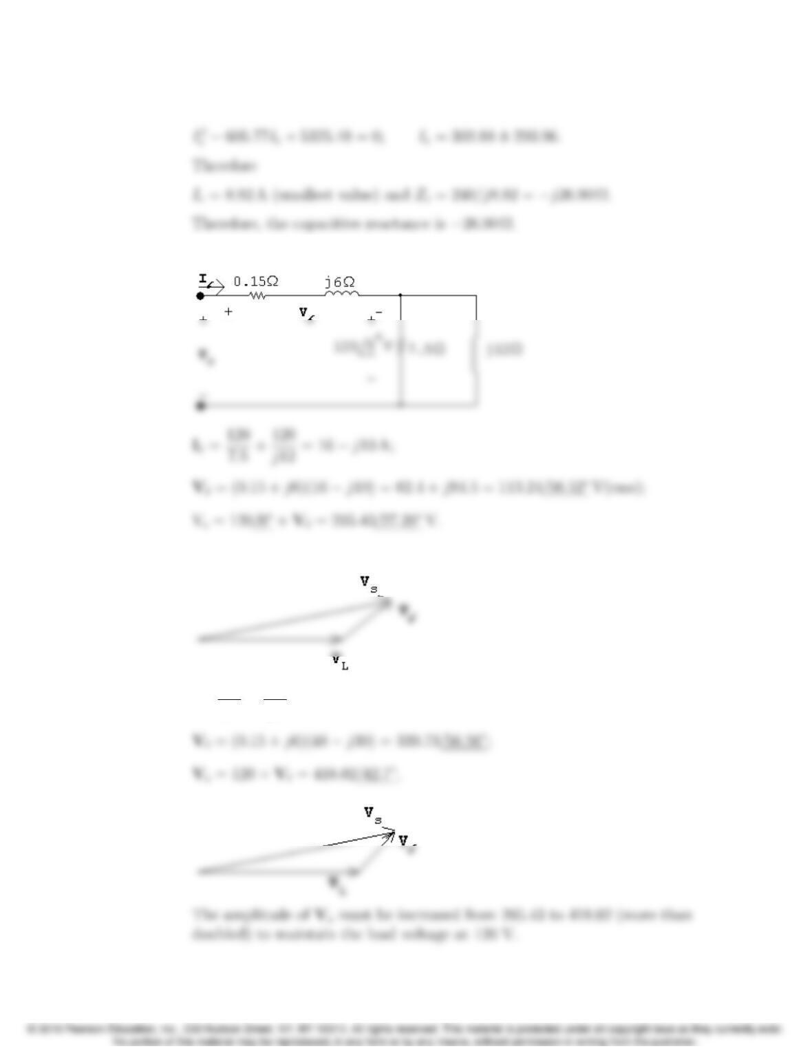
[c] Let Icdenote the magnitude of the current in the capacitor branch. Then
9–54 CHAPTER 9. Sinusoidal Steady State Analysis
Now square each term and then add to generate the quadratic equation
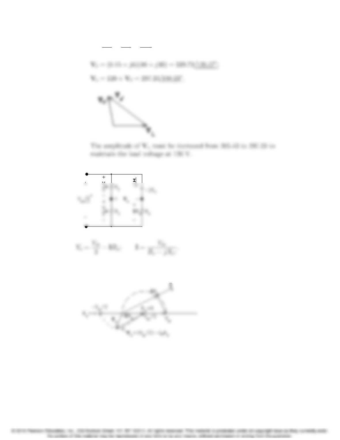
P 9.84 [a]
[b]
[c] I`=120
2.5+120
j4= 48 j30 A;
Problems 9–55
[d] I`=120
2.5+120
j4+120
j2= 48 + j30 A;
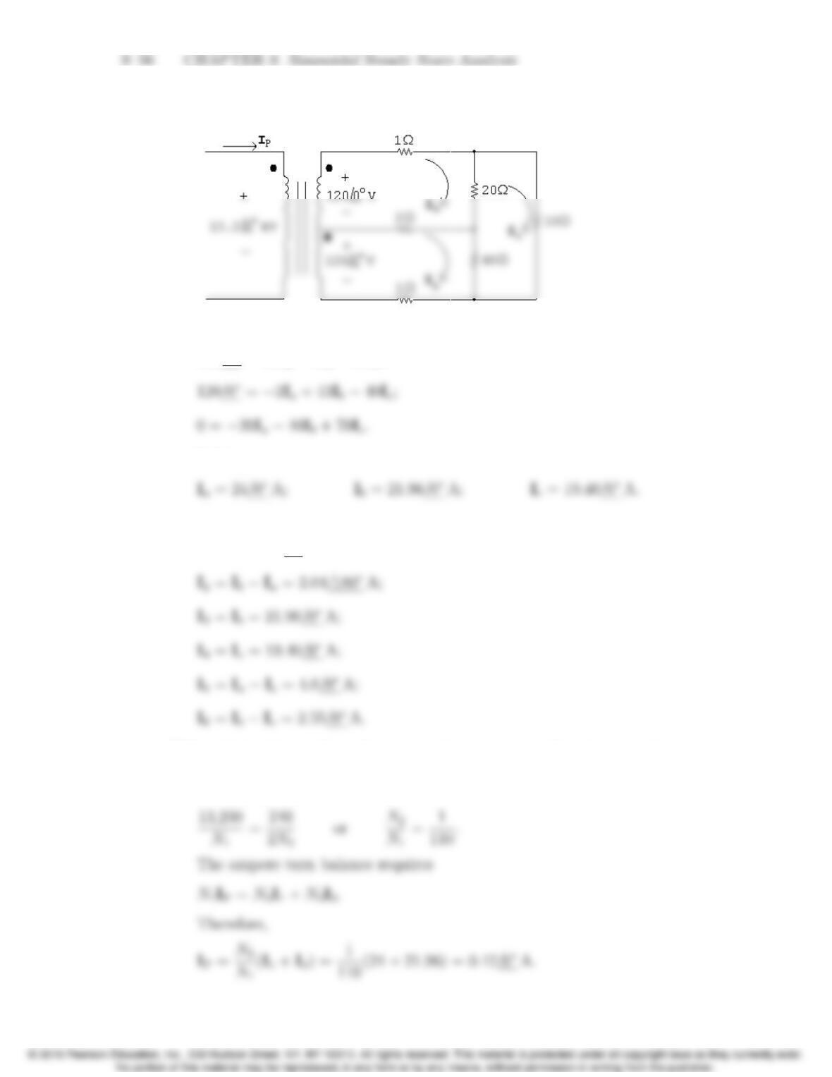
P 9.85 The phasor domain equivalent circuit is
As Rxvaries from 0 to 1,the amplitude of voremains constant and its phase
angle increases from 0to 180, as shown in the following phasor diagram:
P 9.86 [a] The circuit is redrawn, with mesh currents identified:
The mesh current equations are:
120/0= 23Ia2Ib20Ic;
Solving,
The branch currents are:
I1=Ia= 24/0A;
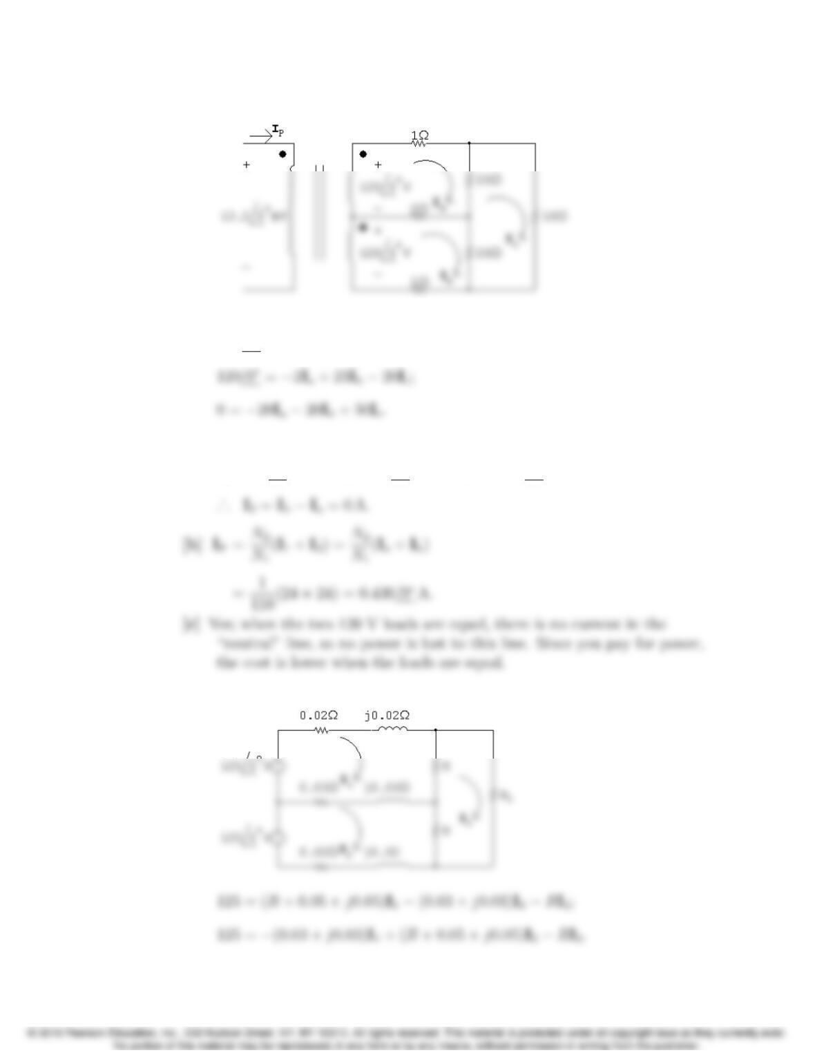
[b] Let N1be the number of turns on the primary winding; because the
secondary winding is center-tapped, let 2N2be the total turns on the
secondary. Therefore,
Problems 9–57
P 9.87 [a]
The three mesh current equations are
120/0= 23Ia2Ib20Ic;
Solving,
Ia= 24/0A; Ib= 24/0A; Ic= 19.2/0A;
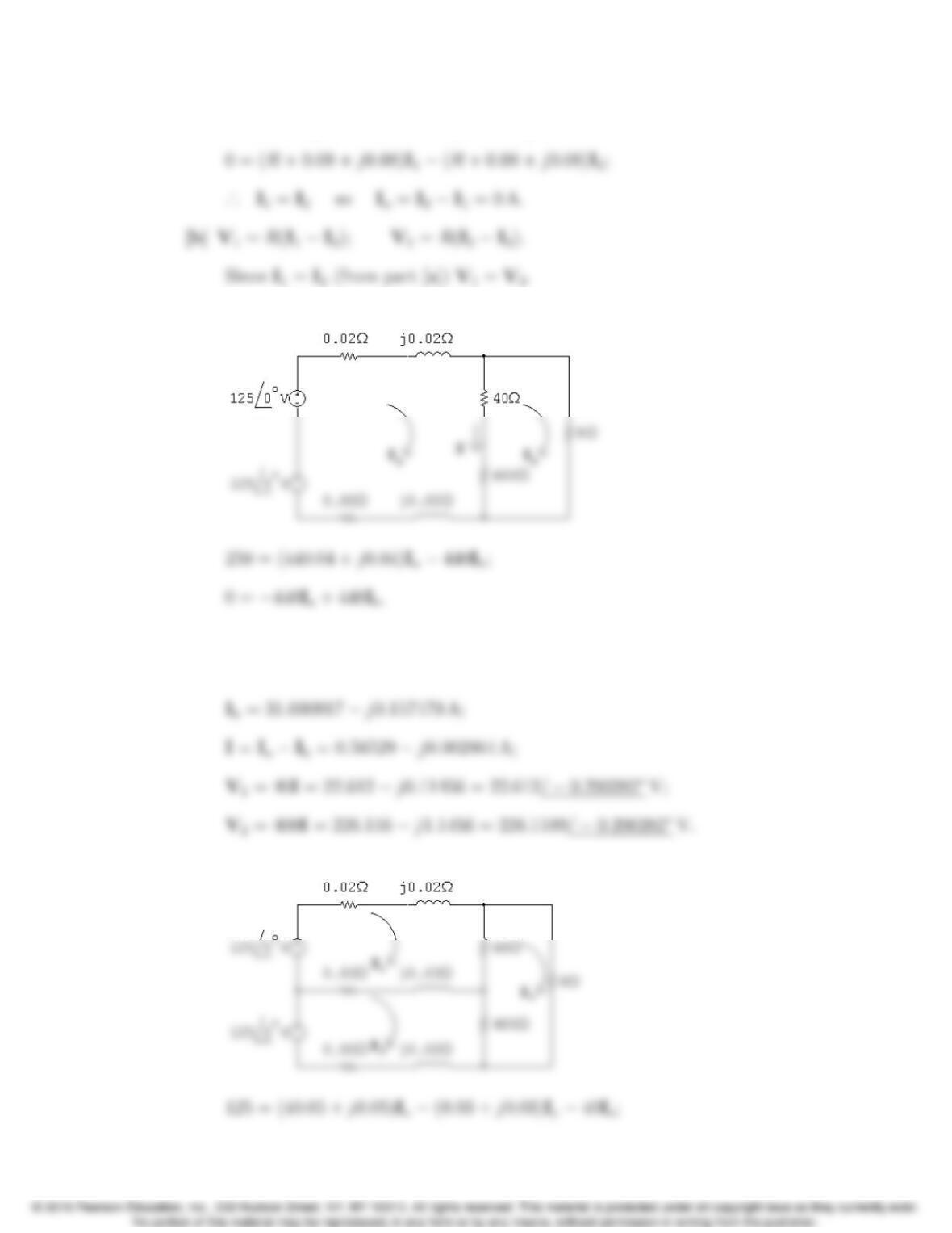
P 9.88 [a]
9–58 CHAPTER 9. Sinusoidal Steady State Analysis
Subtracting the above two equations gives
[c]
Solving,
Ia= 31.656207 j0.160343 A;
[d]
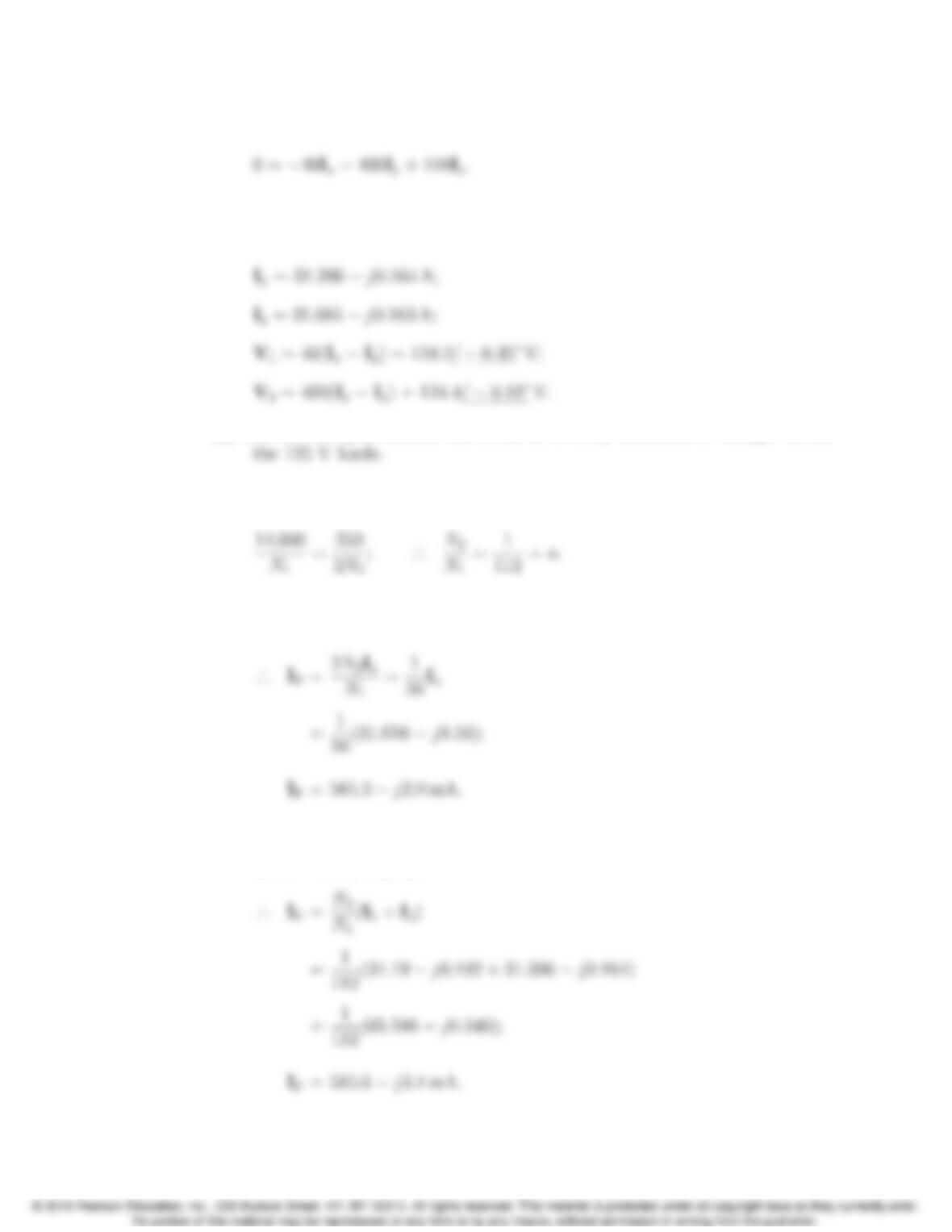
Problems 9–59
125 = (0.03 + j0.03)Ix+ (400.05 + j0.05)Iy400Iz;
Solving,
Ix= 34.19 j0.182 A;
[e] Because an open neutral can result in severely unbalanced voltages across
P 9.89 [a] Let N1= primary winding turns and 2N2= secondary winding turns.
Then
In part c),
IP=2aIa;
In part d),
IPN1=I1N2+I2N2;
9–60 CHAPTER 9. Sinusoidal Steady State Analysis