CHAPTER 9
Exercises
E9.1 The equivalent circuit for the sensor and the input resistance of the
amplifier is shown i Figure 9.2 in the book. Thus the input voltage is
E9.2 (a) A very precise instrument can be very inaccurate because
E9.4 The range of input voltages is from -5 V to +5 V or 10 V in all. We
E9.6 The file containing the vi is named Figure 9.17.vi and can be found on
Problems
P9.1 The elements of a computer-based instrumentation system include
P9.2* The equivalent circuit of a sensor is shown in Figure 9.2 in the book.
Loading effects are caused by the voltage drop across
Rsensor
that
P9.3 The equivalent circuit for a sensor for which the short-circuit current
is proportional to the measurand is
P9.4* The equivalent circuit for the sensor and the input resistance of the
P9.5* We need a current-to-voltage converter that converts the short-
circuit current into a voltage that can be applied to an analog-to–
digital converter. The equivalent circuit is:
P9.6 Bias errors are the same each time a measurement is repeated under
P9.8* Because the accuracy is stated as 0.5% of full scale which is 1 m, the
P9.9 Accuracy is the maximum expected difference in magnitude between
measured and true values (often expressed as a percentage of the
P9.10* (a) Instrument
B
is the most precise because the repeated
measurements vary the least. Instrument
A
is the least precise.
P9.11 The functions of signal conditioners include amplification, conversion
of currents to voltages, supply of (ac or dc) excitations to the sensors
P9.12 One of the two input terminals of a single-ended amplifier is
connected to ground. Neither input terminal of a differential
P9.13 If the input voltages are equal, the differential input voltage is zero.
P9.14*
V 004.0
21
vvvd
P9.15 Refer to Figure 9.7 in the book. We can write
d
cm vvv
2
1
1
and
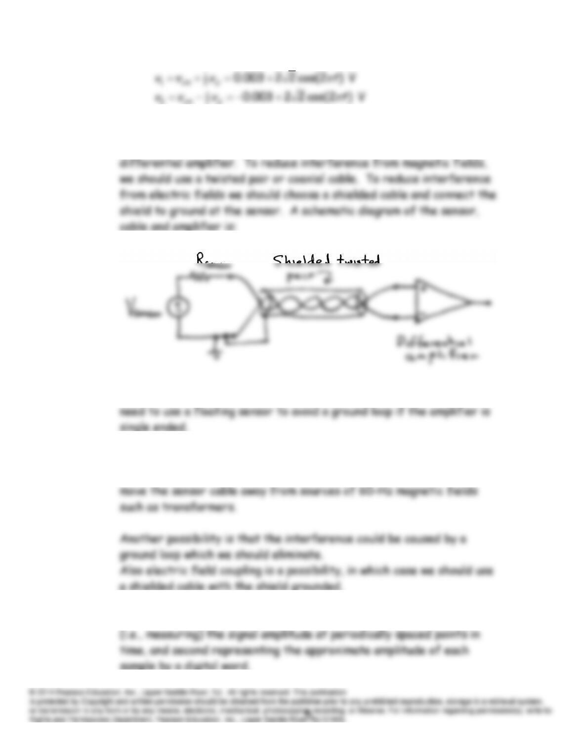
P9.16* To avoid ground loops, we must not have grounds at both ends of the
5-m cable. Because the sensor is grounded, we need to use a
P9.17 Neither terminal of a “floating” sensor is connected to ground. We
P9.18* 60-Hz interference can be caused by magnetic fields linked with the
sensor circuit. We could try a coaxial or twisted pair cable and/or
P9.19 In principle, analog-to-digital conversion consists of first sampling
P9.20 Aliasing is a condition in which a component of a sampled signal has a
P9.21 Quantization noise occurs because finite length digital words can
represent signal amplitudes only approximately. If we reconstruct a
P9.22* The minimum sampling rate is twice the highest frequency. Thus in
theory the sampling rate should be at least 60 kHz. In practice it is
(b) The rms quantization noise is
mV. 705.0)32/(
rms
q
N
This
noise voltage would deliver
P9.25* Refer to Figure 9.14 in the book. For
10
f
kHz, the sampling
frequency must be greater than 20 kHz to avoid aliasing. For each
P9.26 (a) We have
)3/cos()120cos()(
nAnTAnx s
P9.27 We create LabVIEW programs, which are called virtual instruments or
VIs, by positioning and interconnecting icons on a computer screen.
P9.28 LabVIEW uses data flow concepts. This means that the calculations
associated with a specific block are not carried out until all of the
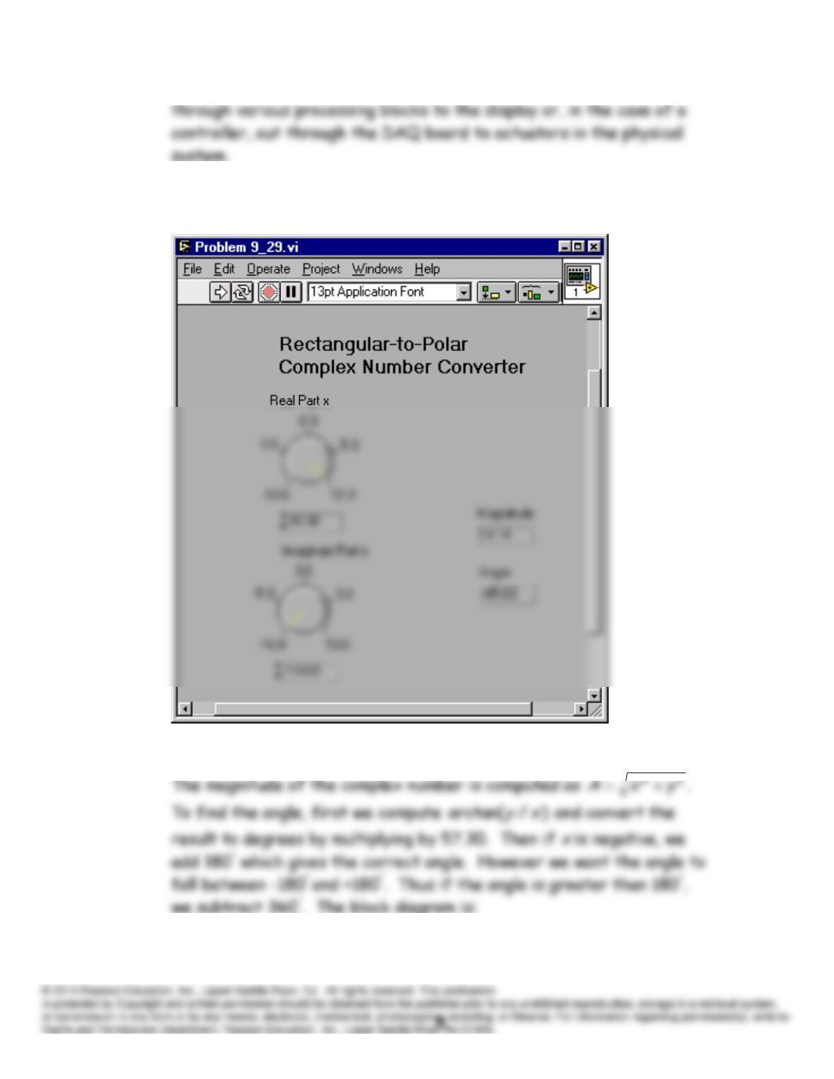
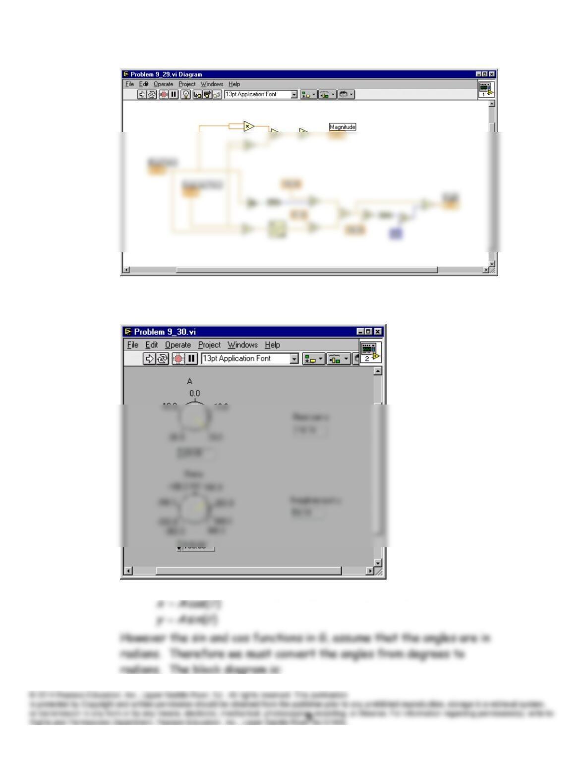
P9.29* The front panel is:
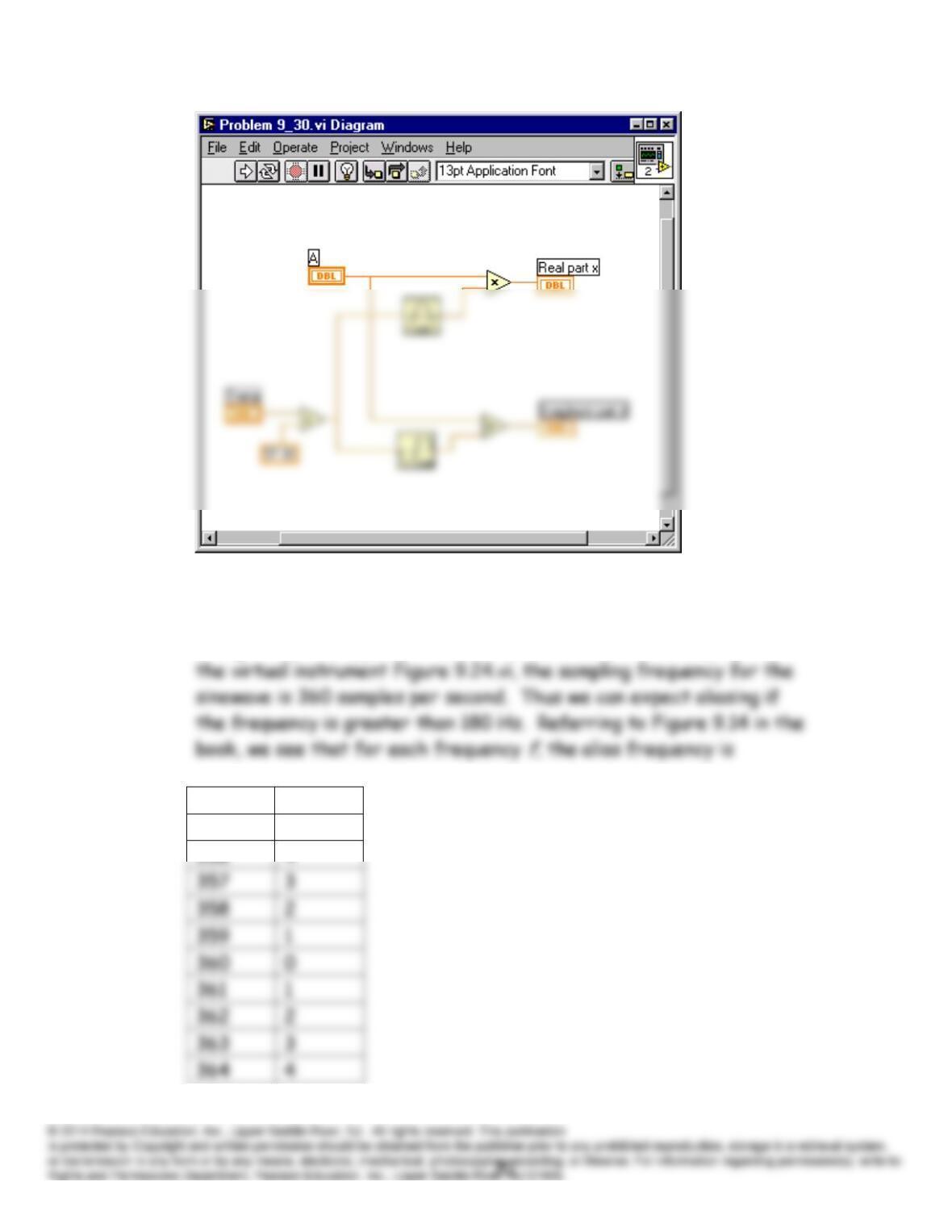
P9.30 The front panel is:
We compute the real and imaginary parts using the equations
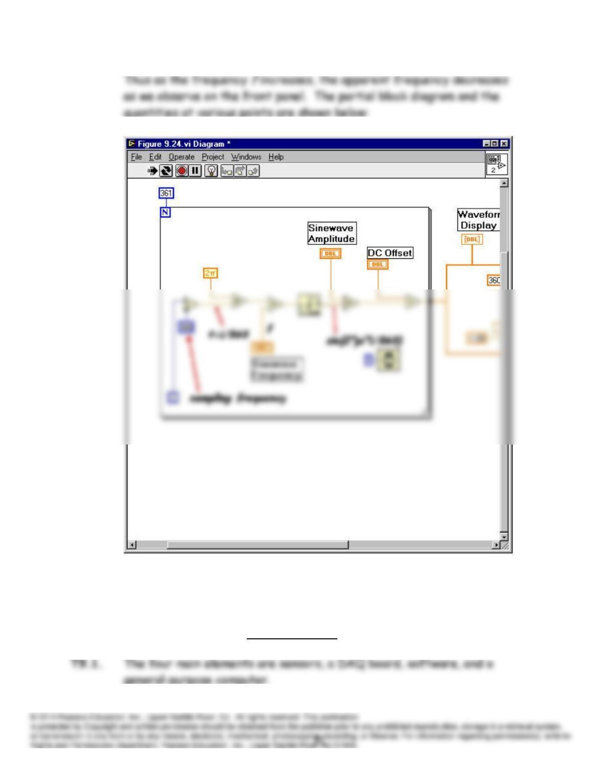
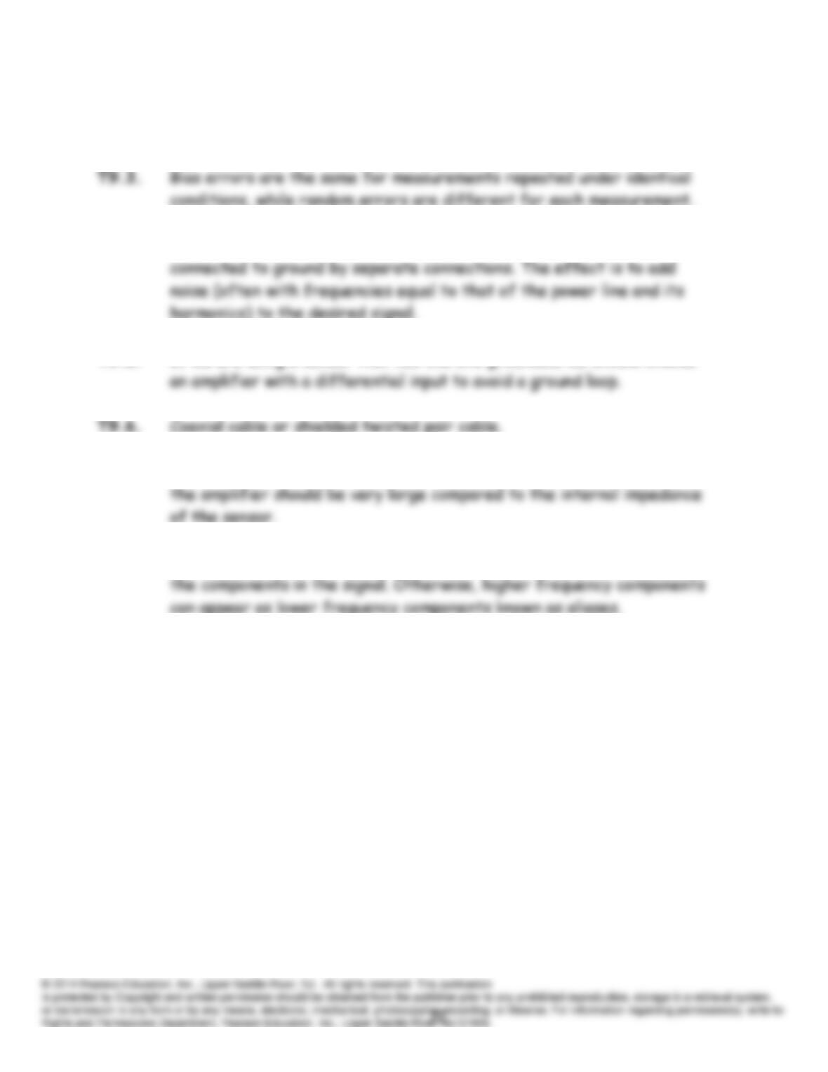
P9.31* We must keep in mind that G-programs deal with sampled signals even
though they may appear to be continuous in time on the displays. In
f
f
alias
355
5
P9.32 Many excellent answers exist.
Practice Test
T9.2. The four types of systematic (bias) errors are offset, scale error,
nonlinearity, and hysteresis.
T9.4. Ground loops occur when the sensor and the input of the amplifier are
T9.5. If we are using a sensor that has one end grounded, we should choose
T9.7. If we need to sense the open-circuit voltage, the input impedance of
T9.8. The sampling rate should be more than twice the highest frequency of