CHAPTER 7
Exercises
E7.1 (a) For the whole part, we have:
Quotient
Remainders
23/2
11
1
11/2
5
1
5/2
2
1
2/2
1
0
1/2
0
1
Reading the remainders in reverse order, we obtain:
(b) For the whole part, we have:
Quotient
Remainders
17/2
8
1
8/2
4
0
4/2
2
0
2/2
1
0
1/2
0
1
Reading the remainders in reverse order, we obtain:
(c) For the whole part we have:
Quotient
Remainders
4/2
2
0
2/2
1
0
1/2
0
1
For the fractional part, we have
Thus we have
E7.3 (a) Using the procedure of Exercise 7.1, we have
(b) Similarly
E7.4 (a) 728 = 111 010 = 1110102
E7.6 To represent a distance of 20 inches with a resolution of 0.01 inches, we
E7.7 (a) First we convert to binary
(b) First we convert +30 to binary form
E7.8 First we convert 1910 and -410 to eight-bit two’s complement form then we
add the results.
E7.10 See Table 7.5 in the book.
finally we invert the entire expression so we have
(b) Following the steps of part (a) we have
E7.12 For the AND gate we use De Morgan’s laws to write
E7.13 The truth table for the exclusive-OR operation is
0
1
1
1
0
1
Focusing on the rows in which the result is 1, we can write the SOP
expression
The corresponding logic diagram is shown in Figure 7.25a in the book.
Focusing on the rows in which the result is 0, we can write the POS
expression
The corresponding logic diagram is shown in Figure 7.25b in the book.
A
B
A
B
0
0
0
E7.14 The truth table is shown in Table 7.7 in the book. Focusing on the rows in
which the result is 1, we can write the SOP expression
Focusing on the rows in which the result is 0, we can write the POS
expression
E7.18 See Figure 7.35 in the book.
E7.19 Because
S
is high at
t
= 0,
Q
is high and remains so until
R
becomes high
Problems
P7.1* 1. When noise is added to a digital signal, the logic levels can still be
3. Very complex digital logic circuits (containing millions of components)
P7.2 The noise margins for a logic circuit are defined as
P7.3 A bit is a binary symbol that can assume values of 0 or 1. A byte is a
P7.4 In positive logic, the logic value 1 is represented by a higher voltage
P7.5 The noise margins for the logic circuits in use are
P7.6 In serial transmission, the bits of a word are transmitted one after
P7.7 Seven-bit words are needed to express the decimal integers 0 through
P7.8 (a)* 5.625
(b) 6.510 = 0110.12 = 0110.0101BCD
P7.11 (a)* FA.F16 = 11111010.11112 = 372.748 = 250.937510
P7.13 (a) Counting in decimal, 378 follows 377.
P7.14 (a)* 313.062510 = 100111001.00012 = 471.048 = 139.116
P7.16 (a)* 777.78 = 111111111.1112 = 1FF.E16 = 511.87510
P7.17 (a) A 4-bit binary number can represent the decimal integers 0 through
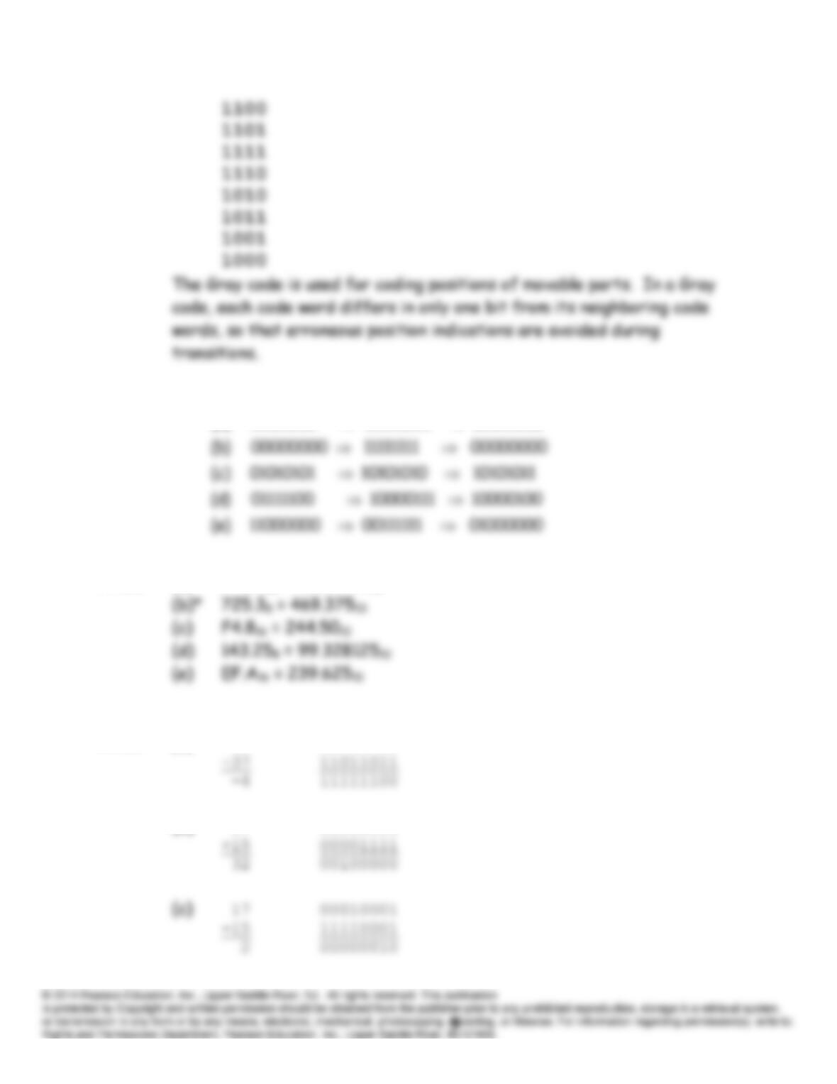
P7.18* Write the 3-bit code shown in Figure 7.9. Then, extend the list by
The resulting four-bit Gray code is:
0000
P7.19
P7.20 (a)* FA5.616 = 4005.37510
P7.21 (a)* 33 00100001
(b) 17 00010001
00011000 00010111 11101000 *(a)
Complement sTwo‘Complement sOne’
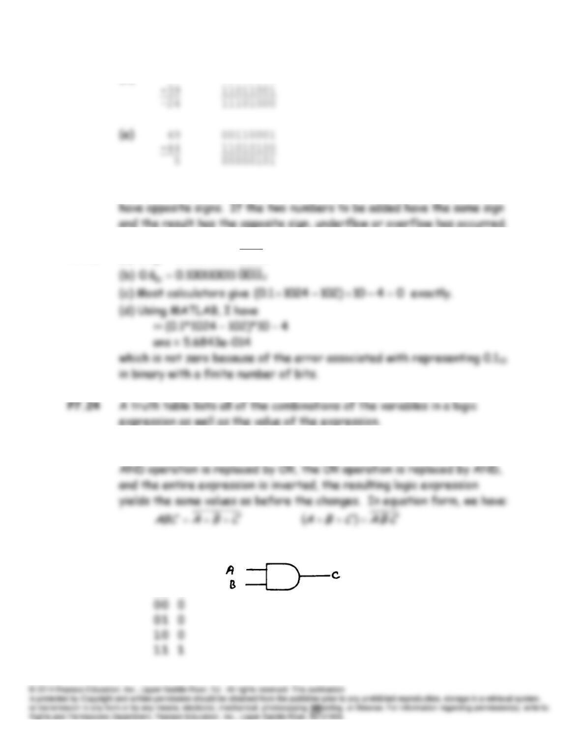
(d) 15 00001111
P7.22 Overflow and underflow are not possible if the two numbers to be added
P7.23 (a)
2
10 0011000110011.01.0
P7.25 If the variables in a logic expression are replaced by their inverses, the
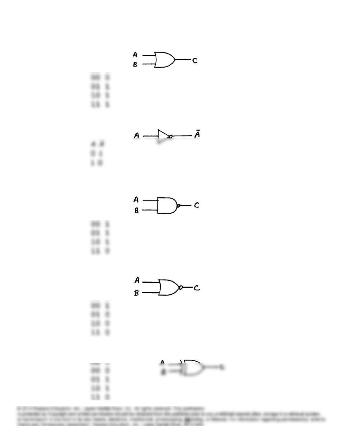
P7.26 AND gate:
AB C
OR gate:
AB C
Inverter:
NAND gate:
AB C
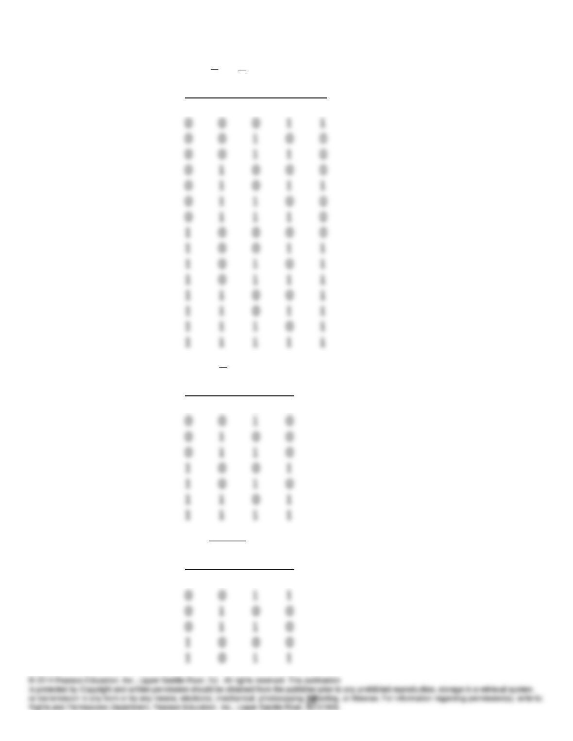
NOR gate:
AB C
Exclusive OR gate:
P7.27 (a)*
DCCBAABE
A B C D E
0 0 0 0 0
(b)
CAABCD
A B C D
0 0 0 0
(c)
YXWXZ
X Y W Z
0 0 0 1
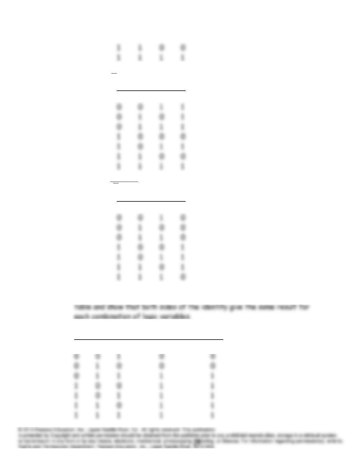
(d)
CBAD
A B C D
0 0 0 0
(e)
BCAD
A B C D
0 0 0 0
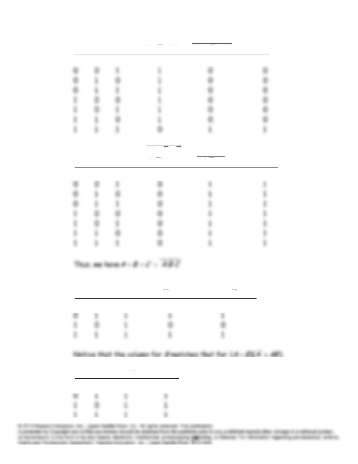
P7.28 One method to prove the validity of a Boolean identity is to list the truth
P7.29*
A B C
(
A
+
B
)(
A
+
C
)
A
+
BC
0 0 0 0 0
P7.30
ABCCBACBACBA
0 0 0 1 0 0
Thus, we have
CBAABC
CBACBACBACBA
0 0 0 1 0 0
P7.31
))((
ABABAABABABA
0 0 0 1 0
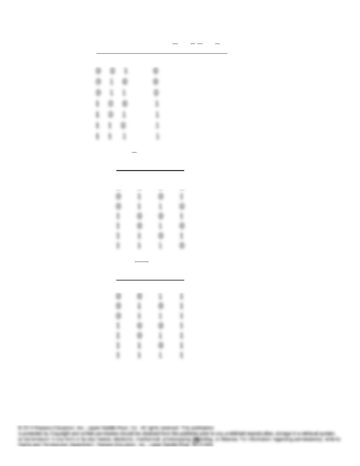
P7.32
BABAABA
0 0 0 0
P7.33
P7.34 (a)
CBAF
A B C F
0 0 0 0
0 0 1 0
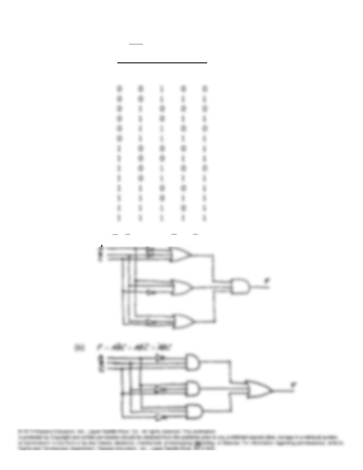
(b)
BCBAF
A B C F
0 0 0 1
0 0 0 0
)(
CBACBACABABCCBA
(c)
DBCABF
A B C D F
0 0 0 0 1
0 0 0 1 1
P7.35 (a)*
CBACBACBAF
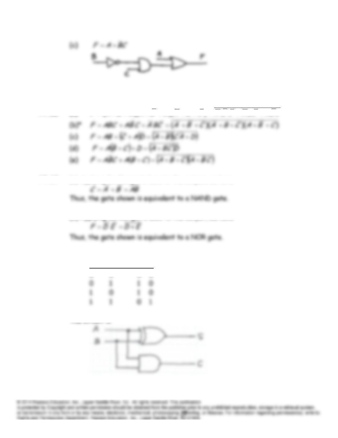
P7.36 (a)*
CBACBACBACBACBACBAF
))()((
P7.37 (a) Applying De Morgan’s laws to the output, we have
(b) Applying De Morgan’s laws to the output, we have
P7.38 The truth table is
A B S C
P7.39 The truth table is
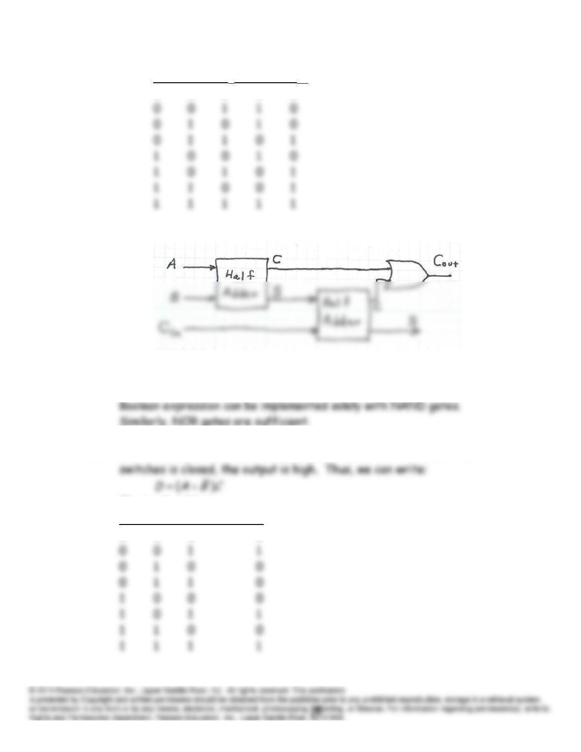
A
B
Cin
S Cout
0 0 0 0 0
The circuit is
P7.40 NAND gates are said to be sufficient for combinatorial logic because any
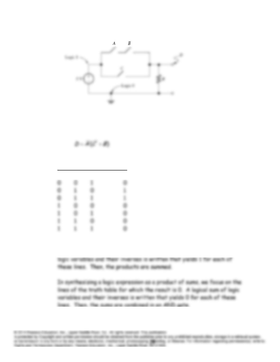
P7.41 In this circuit, if switch
C
is closed and if either of the other two
The truth table is:
A B C D
0 0 0 0
P7.42
P7.43 In this circuit, the output is high only if switch
A
is open (
A
low) and if
either of the other two switches is open. Thus, we can write
The truth table is:
A B C D
0 0 0 1
P7.44 In synthesizing a logic expression as a sum of products, we focus on the
lines of the truth table for which the result is 1. A logical product of

P7.45*
ABCCBACBACBAF
P7.46
BCACBACBAG
P7.47
BCACBACBACBACBAH
P7.48
ABCCABBCACBAI
P7.49
ABCCABBCACBAJ
P7.50
CBACBABCACBAK
P7.51 Applying De Morgan’s Laws to the output of the circuit, we have