Problems 7–77
[b]
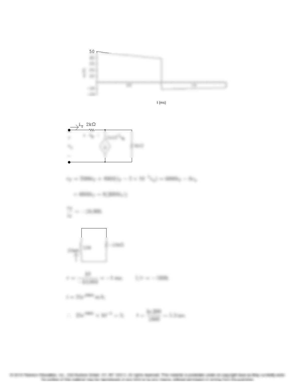
P 7.85
P 7.86 t>0:
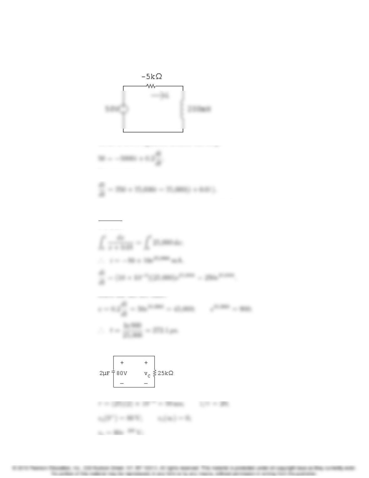
vT= 12 ×104i∆+16×103iT;
P 7.87 Find the Th´evenin equivalent with respect to the terminals of the capacitor.
RTh calculation:
Problems 7–79
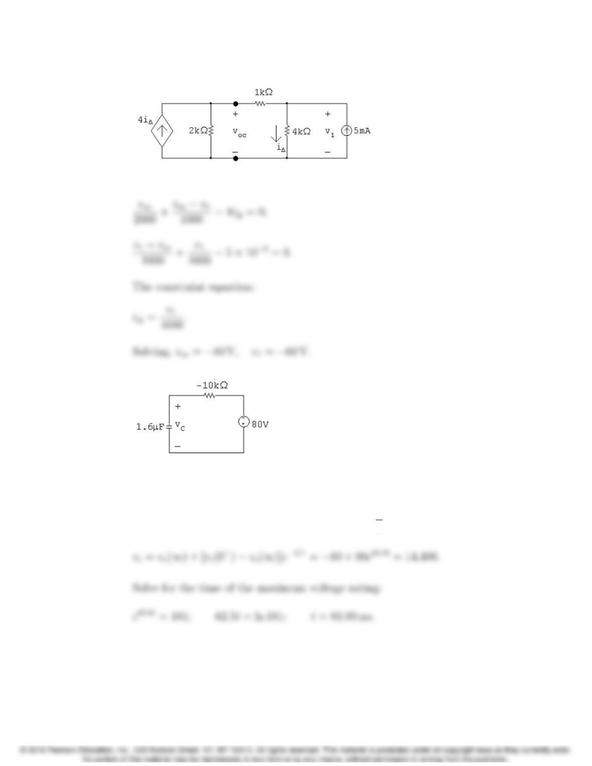
Open circuit voltage calculation:
The node voltage equations:
vc(0) = 0; vc(∞)=−80 V;
τ=RC =(−10,000)(1.6×10⁻⁶)=−16 ms; 1
τ=−62.5;
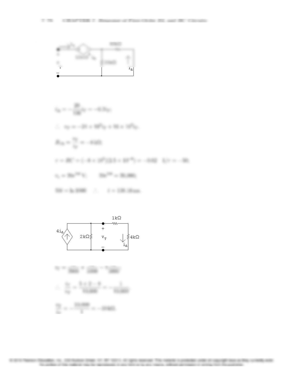
P 7.88 [a]
Using Ohm’s law,
vT= 5000iσ.
Using current division,
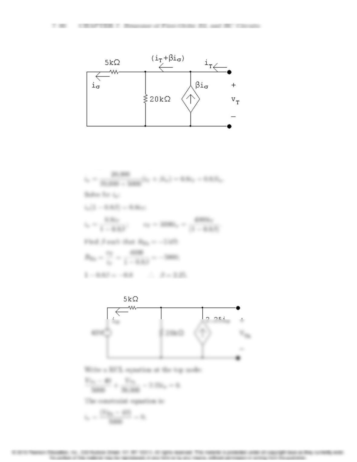
[b] Find VTh:
Problems 7–81
Solving,
VTh = 50 V.
Write a KVL equation around the loop:
Rearranging:
Separate the variables and integrate to find i:
di
i+0.01 = 25,000 dt;
P 7.89 [a]
7–82 CHAPTER 7. Response of First-Order RL and RC Circuits
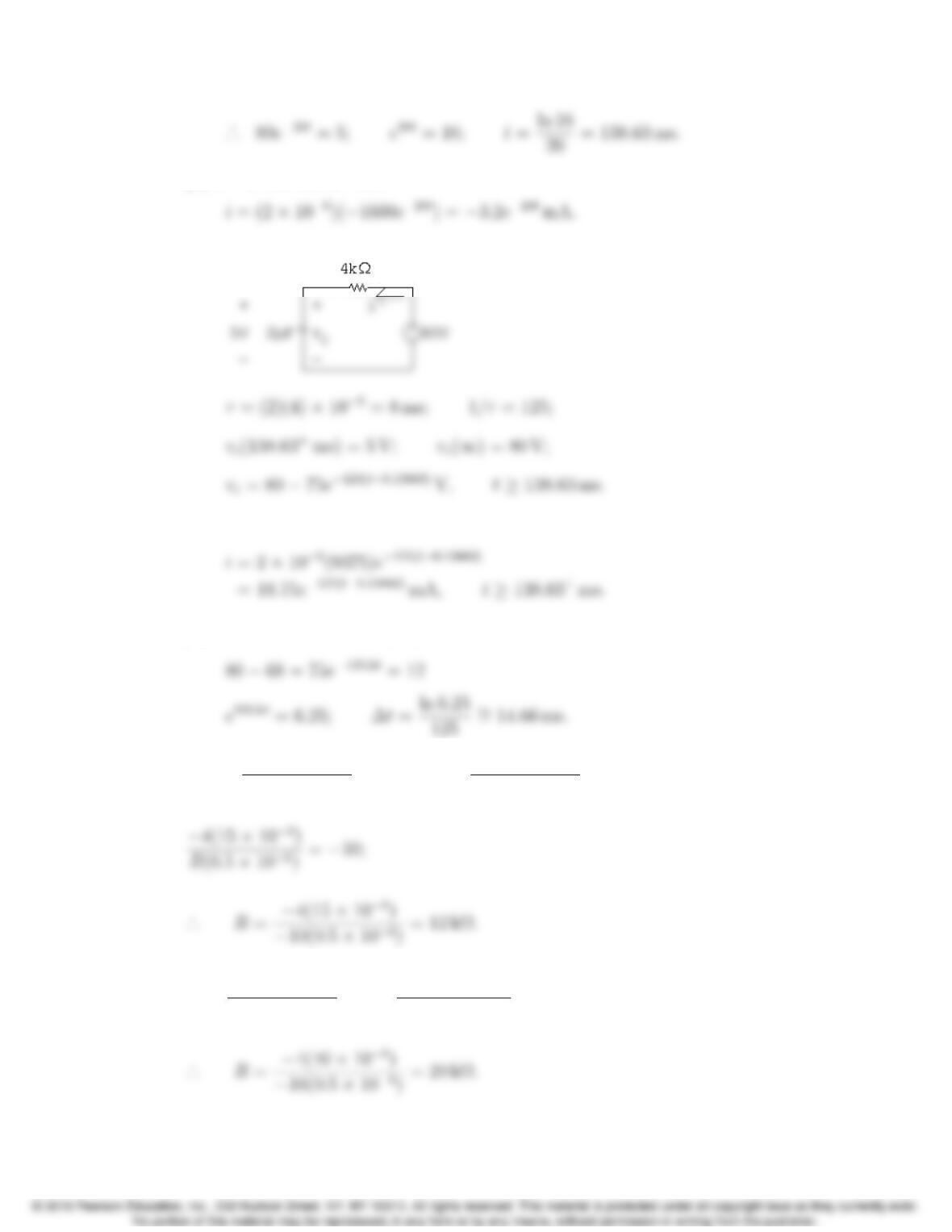
[b] 0+≤t≤138.63−ms:
t≥138.63+ms:
[c] 80 −75e−125∆t=0.85(80) = 68;
P 7.90 vo=−1
R(0.5×10⁻⁶)Zt
04dx +0= −4t
R(0.5×10⁻⁶);
P 7.91 vo=−4t
R(0.5×10⁻⁶)+6= −4(40 ×10−3)
R(0.5×10⁻⁶)+6=−10;
Problems 7–83
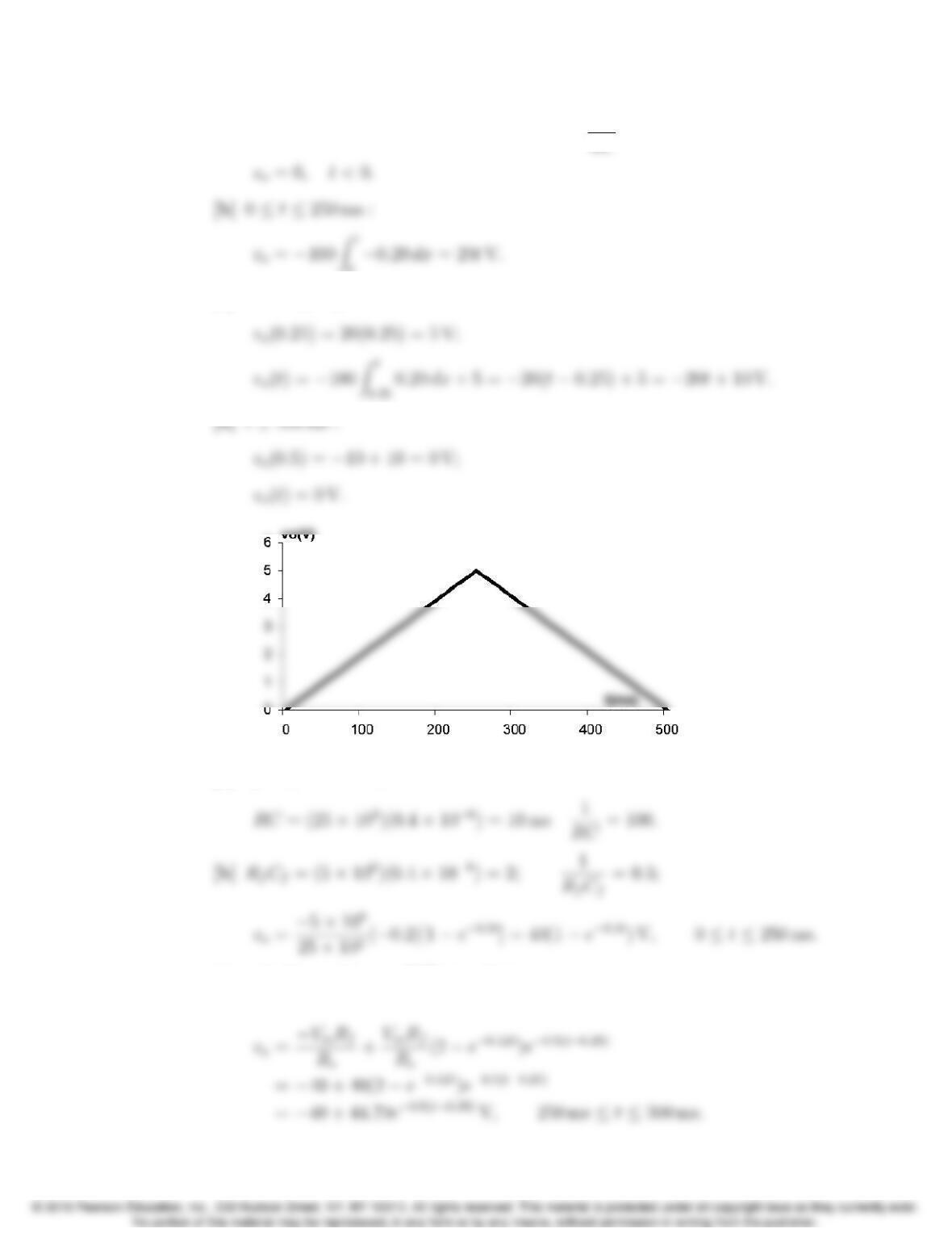
P 7.92 [a] RC = (25 ×103)(0.4×10⁻⁶) = 10 ms; 1
RC = 100;
0
[c] 250 ms ≤t≤500 ms;
P 7.93 [a] vo=0,t<0;
[c] vo(0.25) = 40(1 −e−0.125)∼
=4.70 V;
7–84 CHAPTER 7. Response of First-Order RL and RC Circuits
[d] vo(0.5) = −40 + 44.70e−0.125 ∼
=−0.55 V;
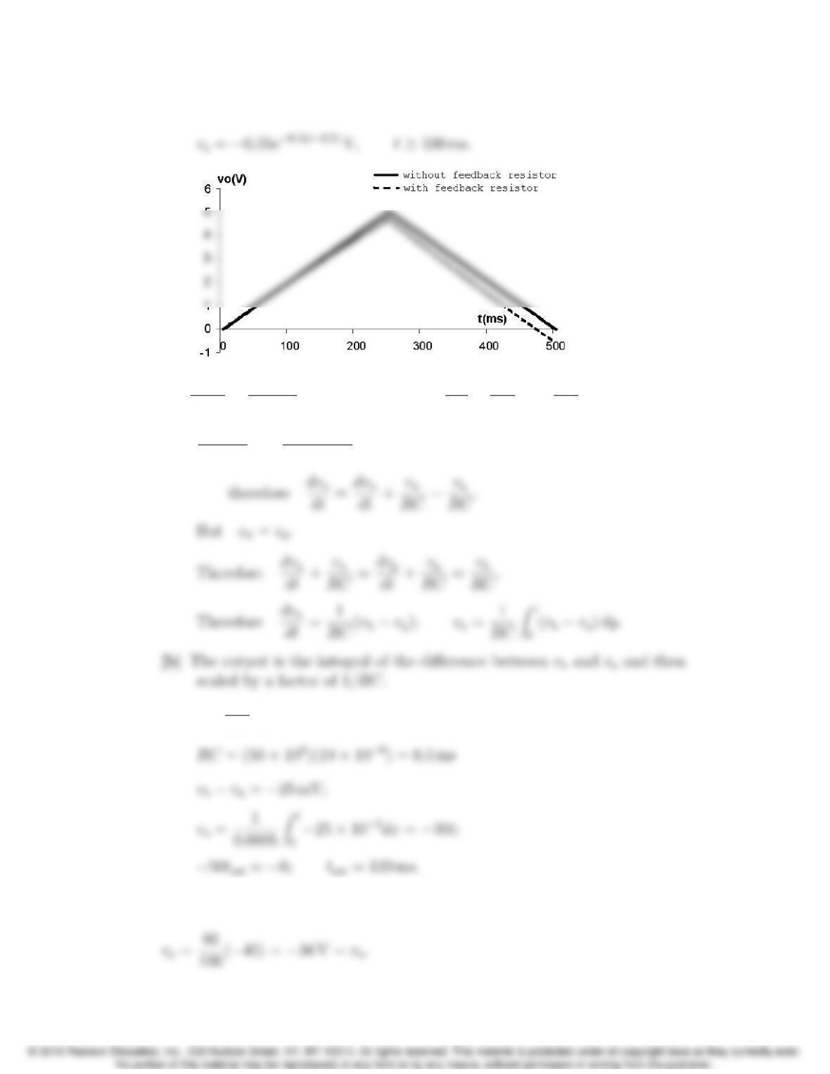
P 7.94 [a] Cdvp
dt +vp−vb
R= 0; therefore dvp
dt +1
RC vp=vb
RC ;
vn−va
R+Cd(vn−vo)
dt = 0;
[c] vo=1
RC Zt
0(vb−va)dx;
P 7.95 Use voltage division to find the voltage at the non-inverting terminal:
Problems 7–85
Write a KCL equation at the inverting terminal:
Separate the variables and integrate:
Find the time when the voltage reaches 0:
P 7.96 [a] RC = (1000)(800 ×10−12) = 800 ×10−9;1
RC =1,250,000.
0≤t≤1µs:
7–86 CHAPTER 7. Response of First-Order RL and RC Circuits
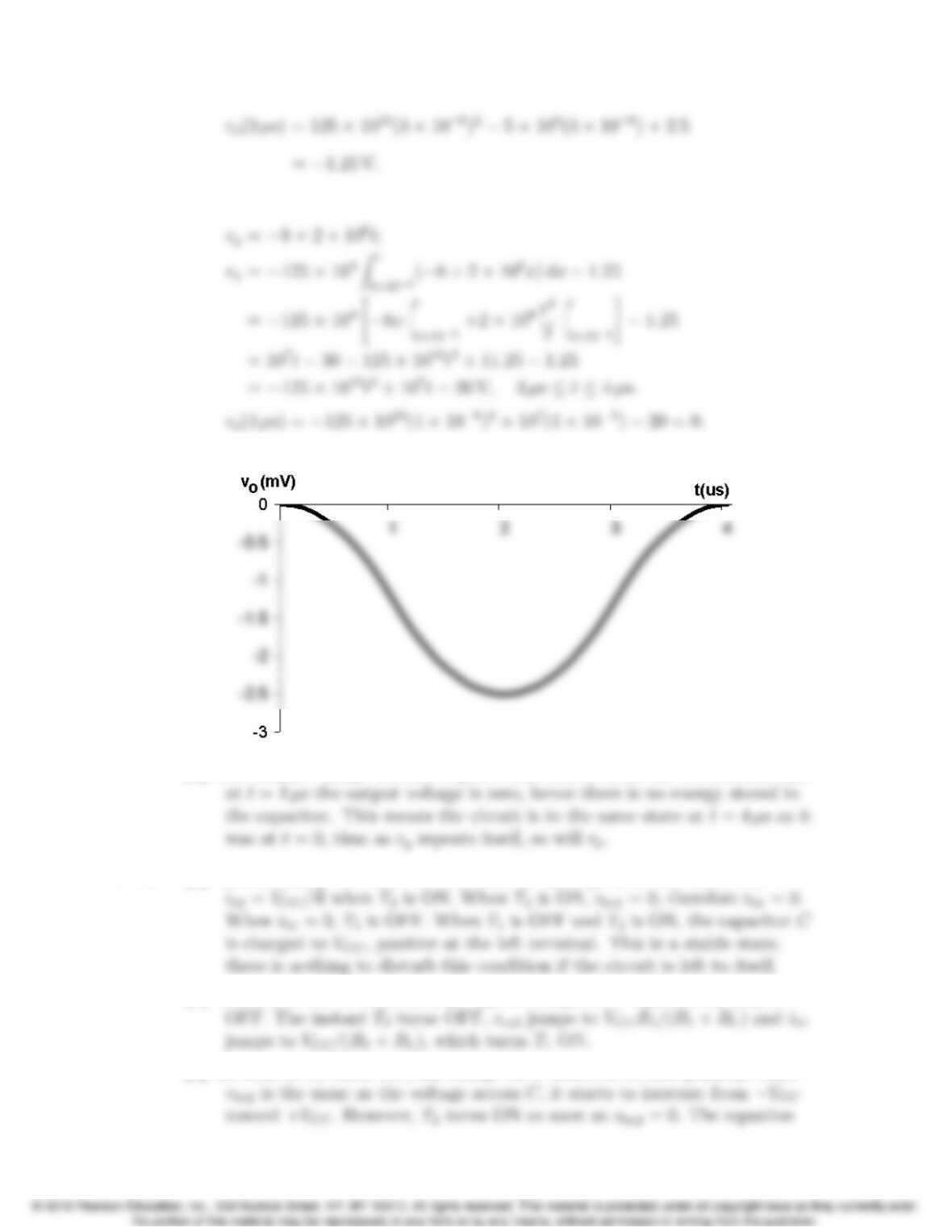
3µs≤t≤4µs:
[b]
[c] The output voltage will also repeat. This follows from the observation that
P 7.97 [a] T2is normally ON since its base current ib2 is greater than zero, i.e.,
[b] When Sis closed momentarily, vbe2 is changed to −VCC and T2snaps
[c] As soon as T1turns ON, the charge on Cstarts to reverse polarity. Since
Problems 7–87
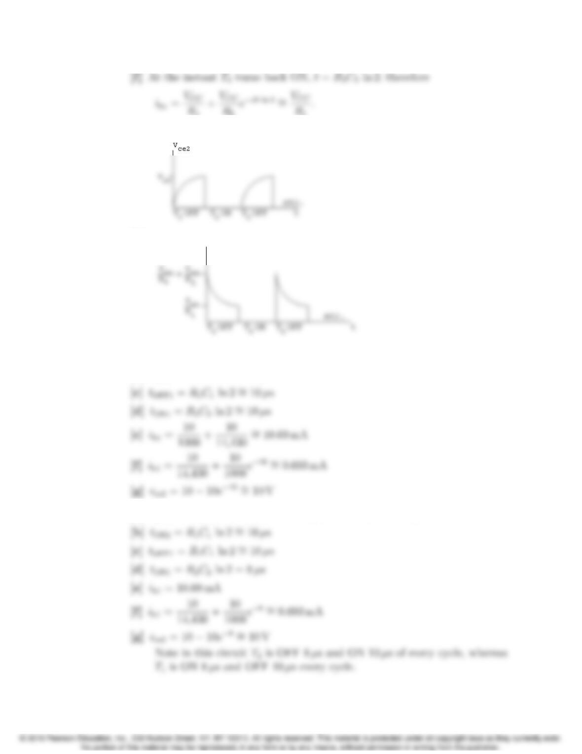
P 7.98 [a] For t<0,v
ce2 =0.When the switch is momentarily closed, vce2 jumps to
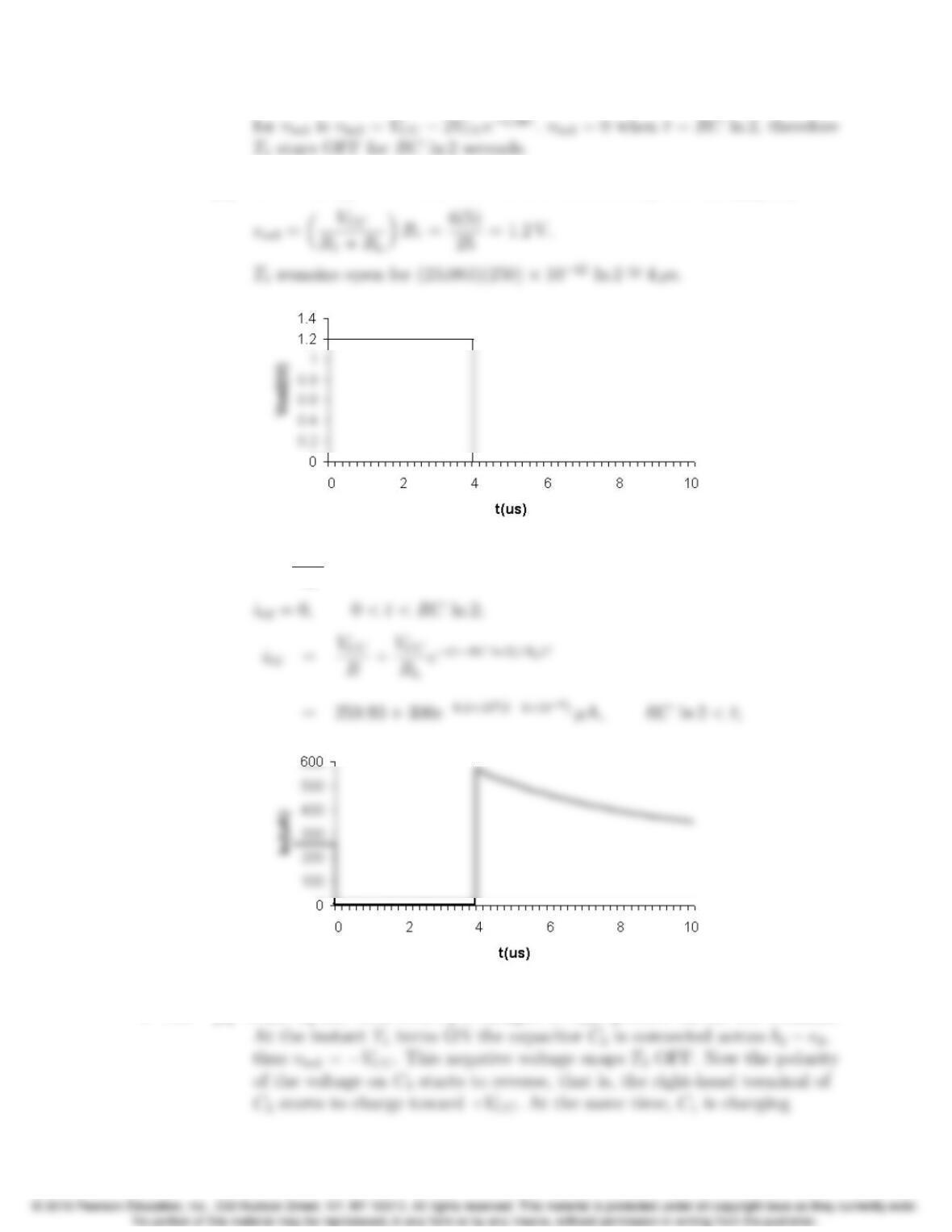
[b] ib2 =VCC
R= 259.93 µA,−5≤t≤0µs;
P 7.99 [a] While T2has been ON, C2is charged to VCC,positive on the left terminal.
7–88 CHAPTER 7. Response of First-Order RL and RC Circuits
[b] While T2is OFF and T1is ON, the output voltage vce2 is the same as the
voltage across C1,thus
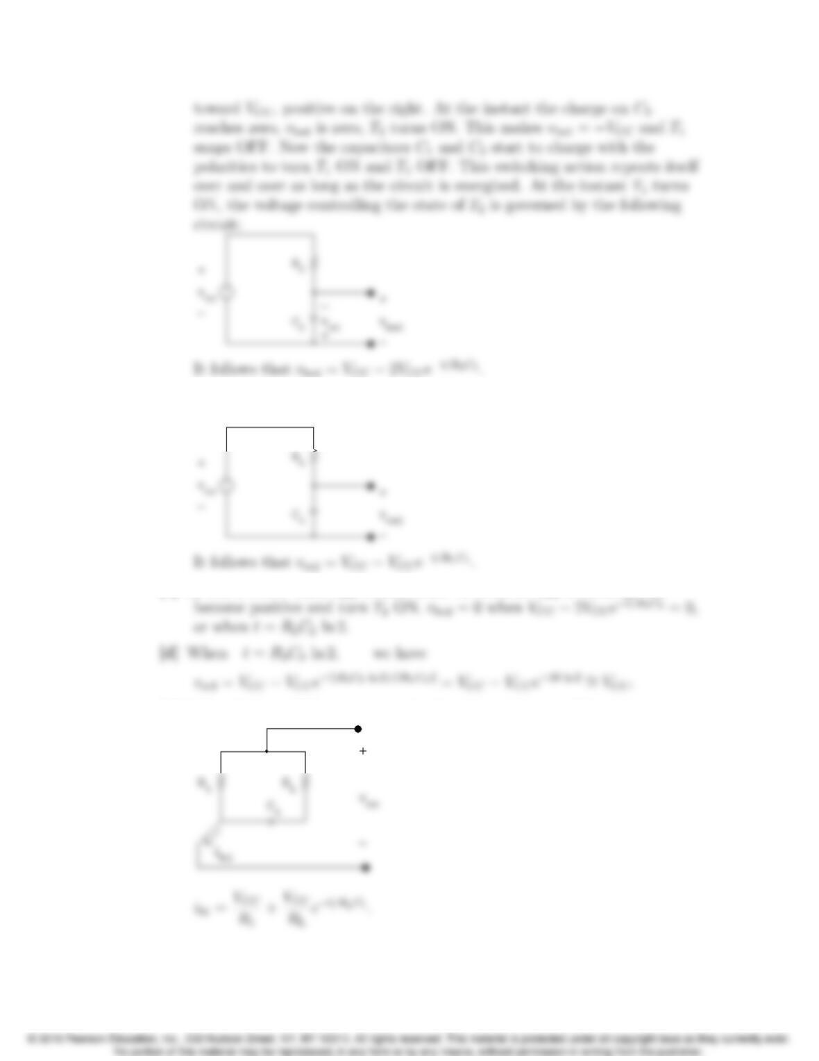
[c] T2will be OFF until vbe2 reaches zero. As soon as vbe2 is zero, ib2 will
[e] Before T1turns ON, ib1 is zero. At the instant T1turns ON, we have
Problems 7–89
[g]
[h]
P 7.100 [a] tOFF2 =R2C2ln 2 = 14.43 ×10³(1 ×10⁻⁹) ln 2 ∼
=10 µs
[b] tON2 =R1C1ln 2 ∼
=10 µs
P 7.101 [a] tOFF2 =R2C2ln 2 = (14.43 ×10³)(0.8×10⁻⁹) ln 2 ∼
=8µs
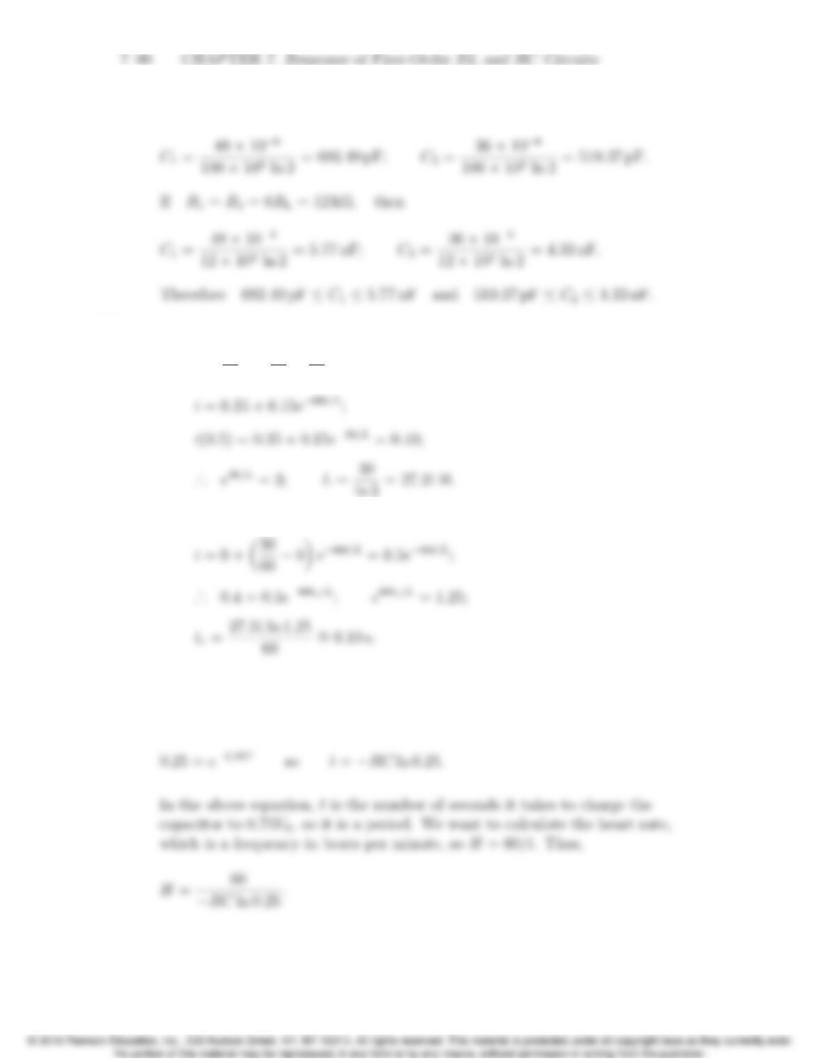
P 7.102 If R1=R2= 50RL= 100 kΩ,then
P 7.103 [a] 0≤t≤0.5:
i=21
60 +✓30
60 −21
60◆e−t/τwhere τ=L/R.
[b] 0≤t≤tr, where tris the time the relay releases:
P 7.104 From the Practical Perspective,
vC(t)=0.75VS=VS(1 −e−t/RC ).
P 7.105 In this problem, Vmax =0.6VS, so the equation for heart rate in beats per
minute is
H=60
−RC ln 0.4.
P 7.106 From the Practical Perspective,
Solve this equation for the resistance R:
Then, −t
RC = ln ✓1−Vmax
VS◆;
In the above equation, tis the time it takes to charge the capacitor to a
voltage of Vmax. But tand the heart rate Hare related as follows:
P 7.107 From Problem 7.106,
7–92 CHAPTER 7. Response of First-Order RL and RC Circuits
Note that from the problem statement,