Response of First-Order RL and
RC Circuits
Assessment Problems
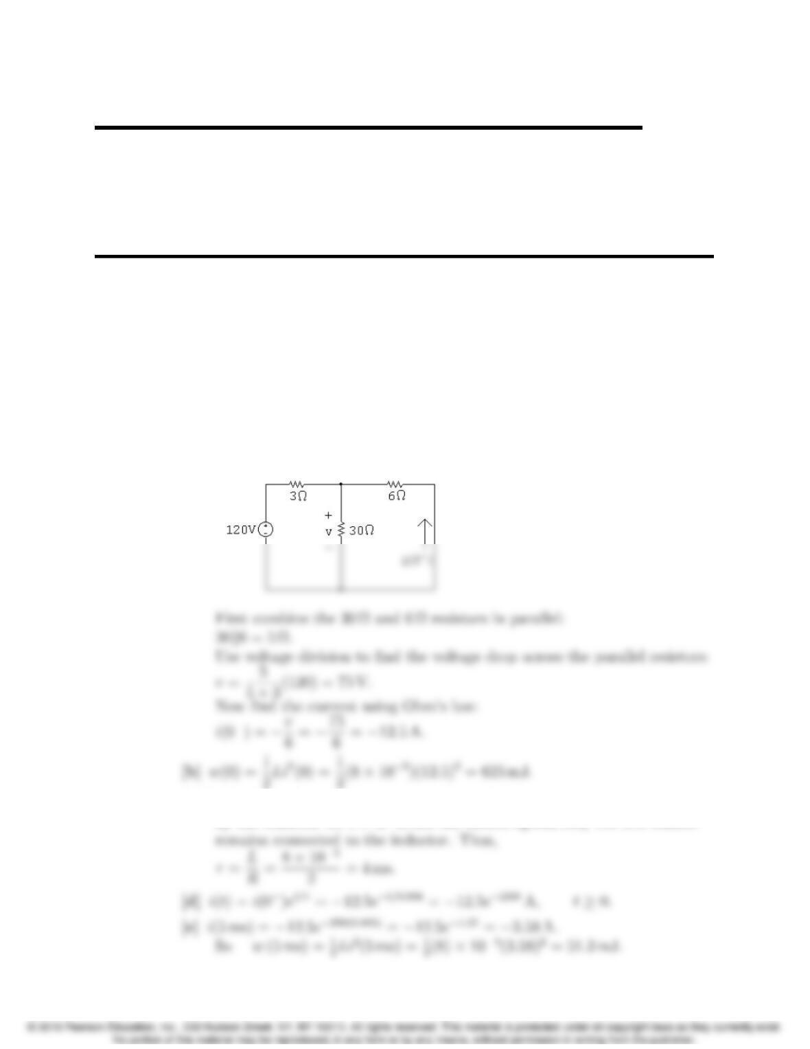
AP 7.1 [a] The circuit for t<0 is shown below. Note that the inductor behaves like a
short circuit, effectively eliminating the 2 Ωresistor from the circuit.
[c] To find the time constant, we need to find the equivalent resistance seen
by the inductor for t>0. When the switch opens, only the 2 Ωresistor
7–1
7
7–2 CHAPTER 7. Response of First-Order RL and RC Circuits
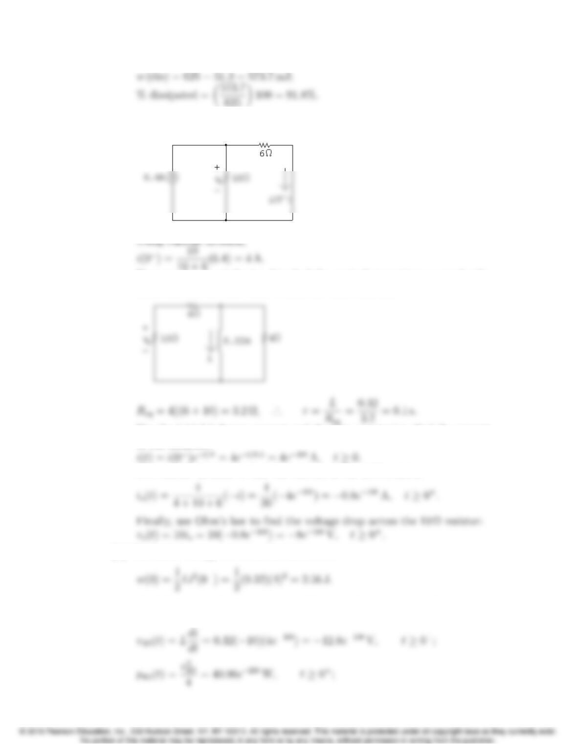
AP 7.2 [a] First, use the circuit for t<0 to find the initial current in the inductor:
Now use the circuit for t>0 to find the equivalent resistance seen by the
inductor, and use this value to find the time constant:
Use the initial inductor current and the time constant to find the current
in the inductor:
Use current division to find the current in the 10 Ωresistor:
[b] The initial energy stored in the inductor is
Find the energy dissipated in the 4 Ωresistor by integrating the power
over all time:
Problems 7–3
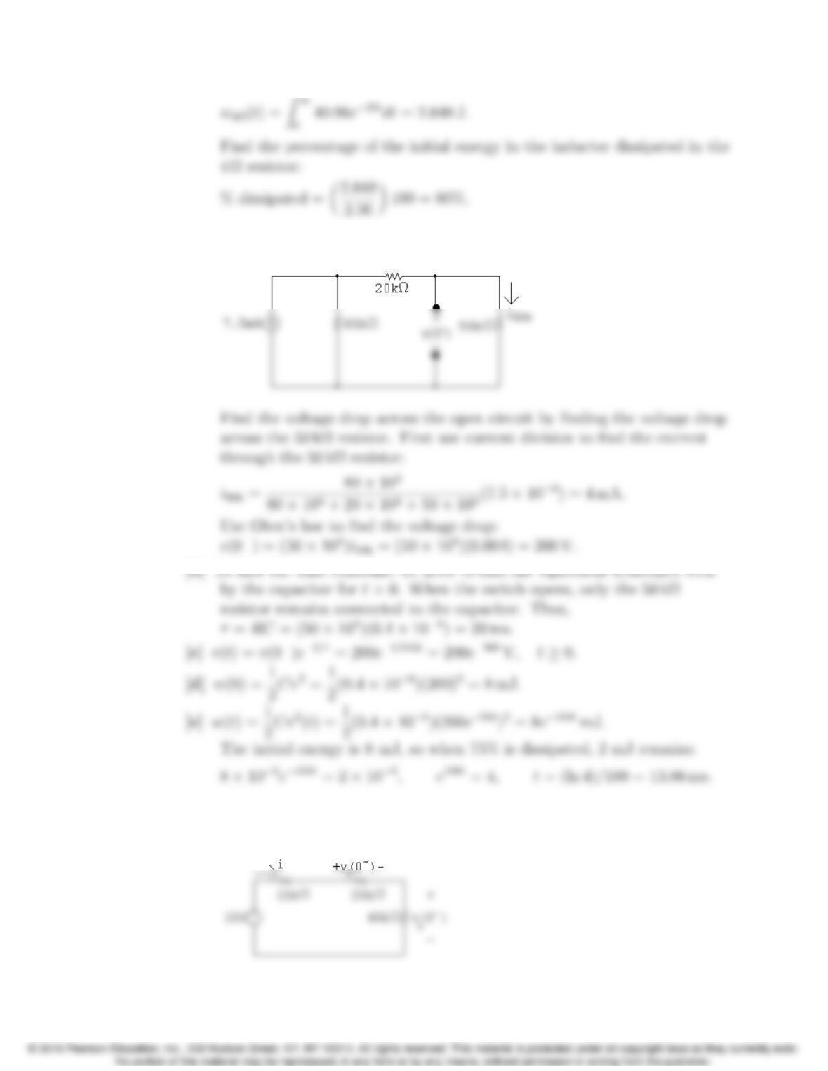
AP 7.3 [a] The circuit for t<0 is shown below. Note that the capacitor behaves like
an open circuit.
AP 7.4 [a] This circuit is actually two RC circuits in series, and the requested
voltage, vo, is the sum of the voltage drops for the two RC circuits. The
circuit for t<0 is shown below:
7–4 CHAPTER 7. Response of First-Order RL and RC Circuits
Find the current in the loop and use it to find the initial voltage drops
across the two RC circuits:
[b] Find the value of the voltage at 60 ms for each subcircuit and use the
voltage to find the energy at 60 ms:
v1(60 ms) = 8e−25(0.06) ⇠
=1.79 V,v
5(60 ms) = 4e−10(0.06) ⇠
=2.20 V;
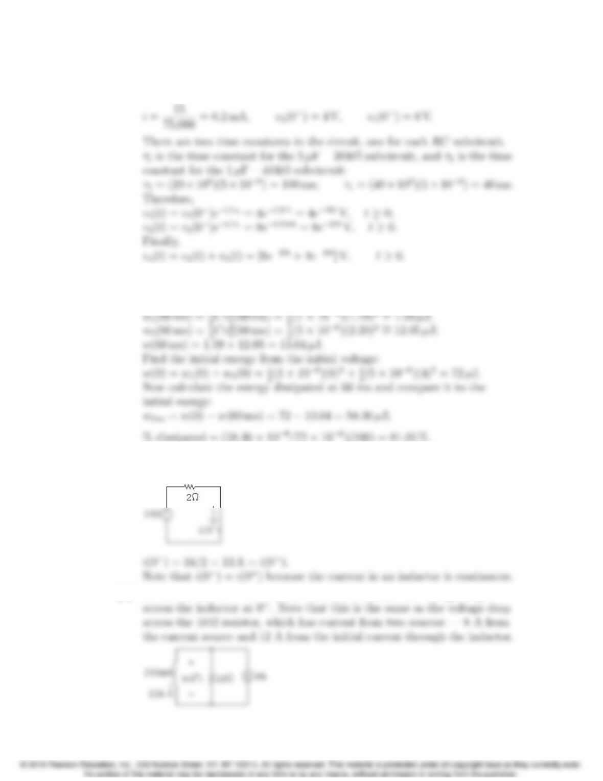
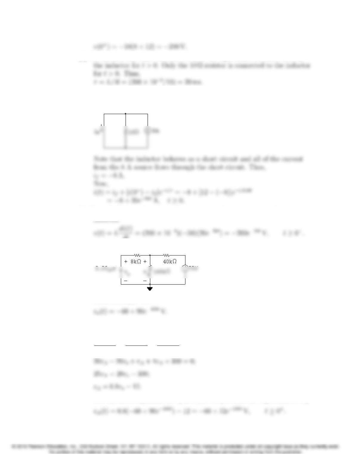
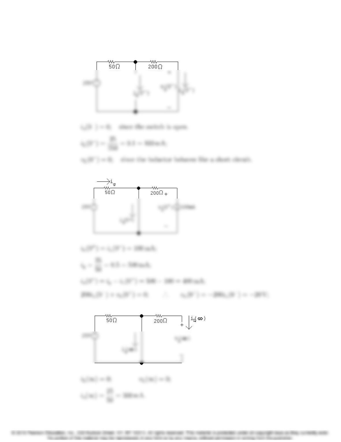
AP 7.5 [a] Use the circuit at t<0, shown below, to calculate the initial current in
the inductor:
[b] Use the circuit at t=0
+, shown below, to calculate the voltage drop
Problems 7–5
[c] To calculate the time constant we need the equivalent resistance seen by
[d] To find i(t), we need to find the final value of the current in the inductor.
When the switch has been in position a for a long time, the circuit
reduces to the one below:
[e] To find v(t), use the relationship between voltage and current for an
dt = (200 ⇥10−3)(50)(20e−50t)=200e−50tV,t0+.
AP 7.6 [a]
From Example 7.6,
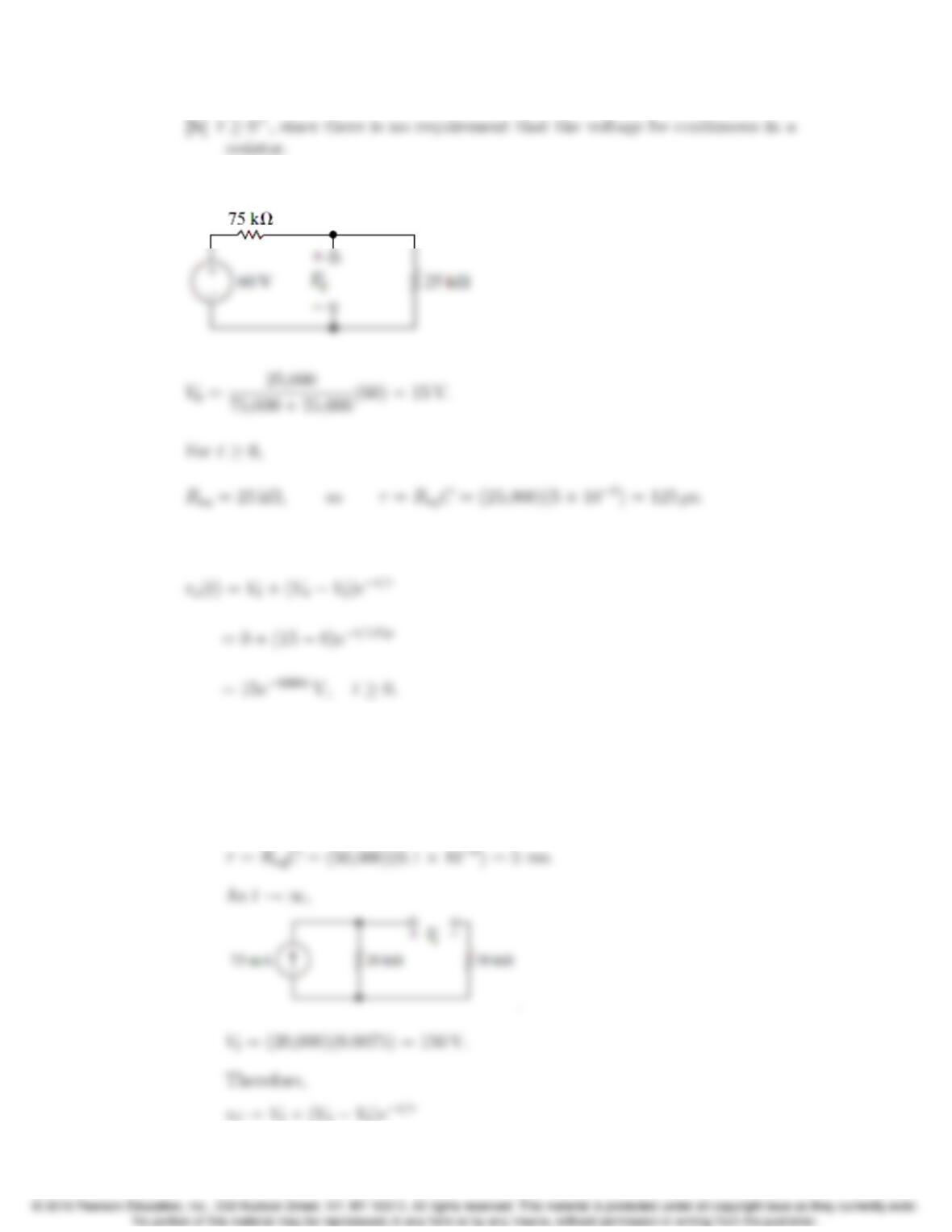
Write a KCL equation at the top node and use it to find the relationship
between voand vA:
vAvo
8000 +vA
160,000 +vA+75
40,000 = 0;
Use the above equation for vAin terms of voto find the expression for vA:
7–6 CHAPTER 7. Response of First-Order RL and RC Circuits
AP 7.7 For t<0,
There is no source in the circuit as t!1so Vf= 0. Thus,
AP 7.8 [a] Find the voltage across the capacitor in the direction of the capacitor
current. Call this voltage vc. The initial capacitor charge is zero, so
V0= 0. For t0,
Req = 20,000 + 30,000 = 50,000 Ω;
Problems 7–7
Thus,
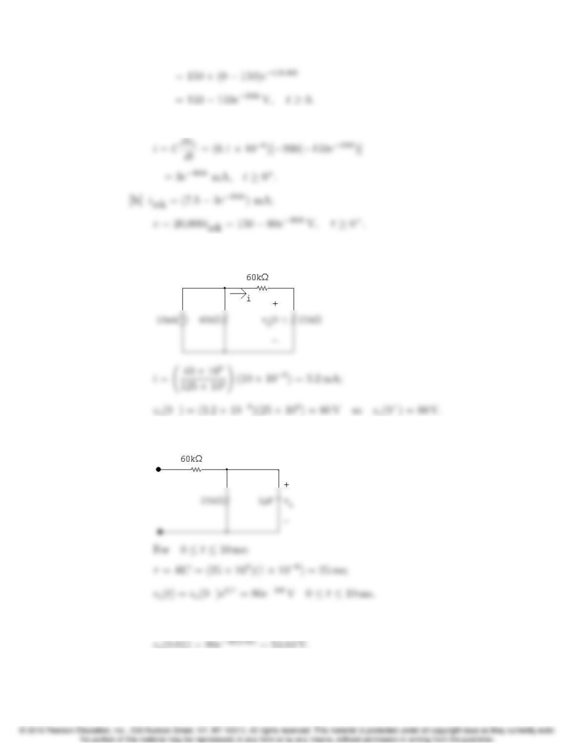
AP 7.9 [a] Use the circuit shown below, for t<0, to calculate the initial voltage drop
across the capacitor:
Now use the next circuit, valid for 0 t10 ms, to calculate vc(t) for
that interval:
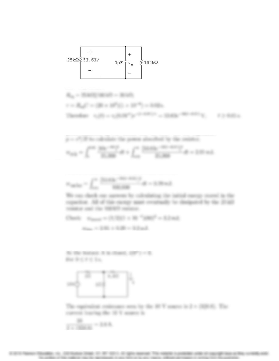
[b] Calculate the starting capacitor voltage in the interval t10 ms, using
the capacitor voltage from the previous interval:
7–8 CHAPTER 7. Response of First-Order RL and RC Circuits
Now use the next circuit, valid for t10 ms, to calculate vc(t) for that
interval:
For t10 ms :
[c] To calculate the energy dissipated in the 25 kΩresistor, integrate the
power absorbed by the resistor over all time. Use the expression
[d] Repeat the process in part (c), but recognize that the voltage across this
resistor is non-zero only for the second interval:
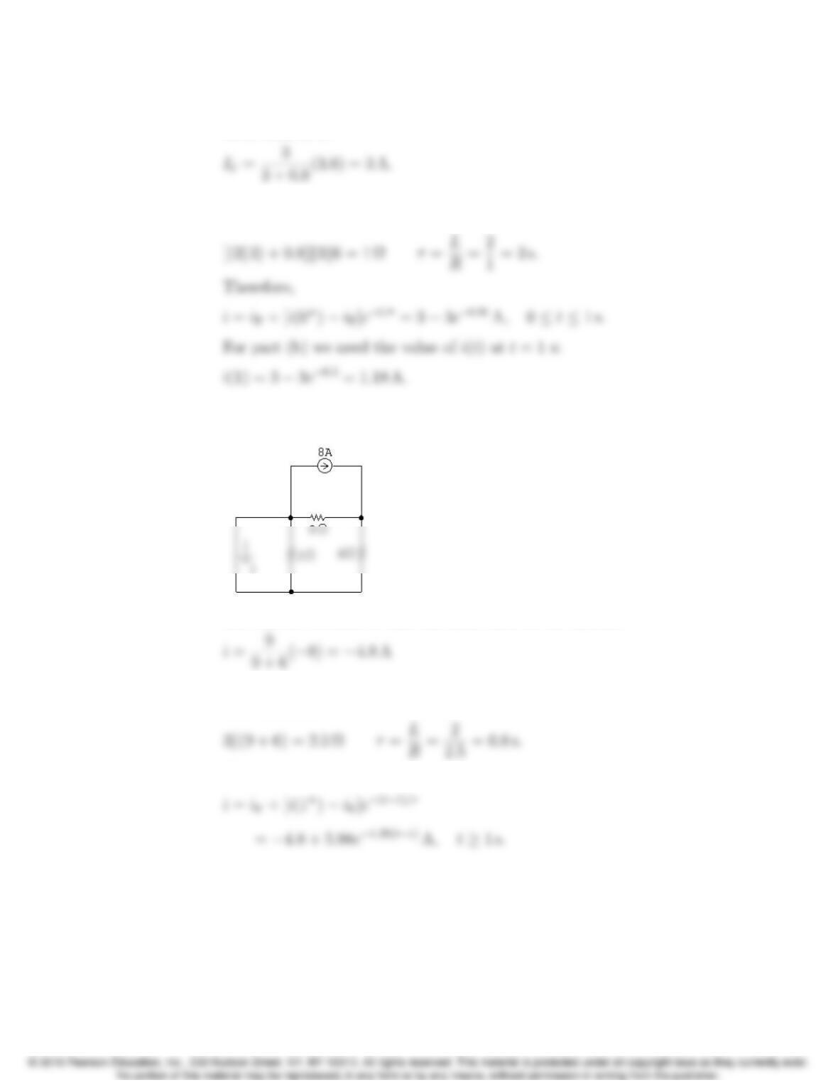
AP 7.10 [a] Prior to switch a closing at t= 0, there are no sources connected to the
inductor; thus, i(0−)=0.
Problems 7–9
The final current in the inductor, which is equal to the current in the
0.8Ωresistor is
The resistance seen by the inductor is calculated to find the time
constant:
.
[b] For t>1s
Use current division to find the final value of the current:
The equivalent resistance seen by the inductor is used to calculate the
time constant:
Therefore,
7–10 CHAPTER 7. Response of First-Order RL and RC Circuits
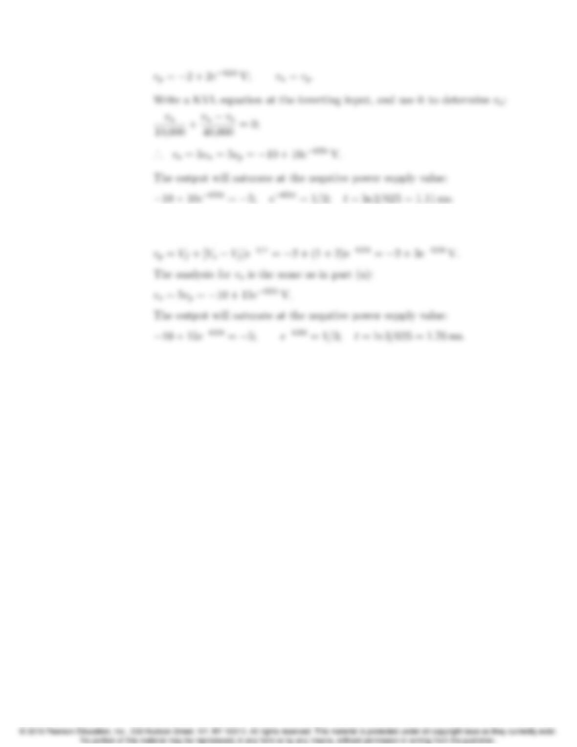
AP 7.11 0 t32 ms:
vo=1
RCfZ32×10−3
010 dt +0=1
RCf
(10t)
32×10−3
0
=1
RCf
(320 ⇥10−3);
t32 ms:
The output will saturate at the negative power supply value:
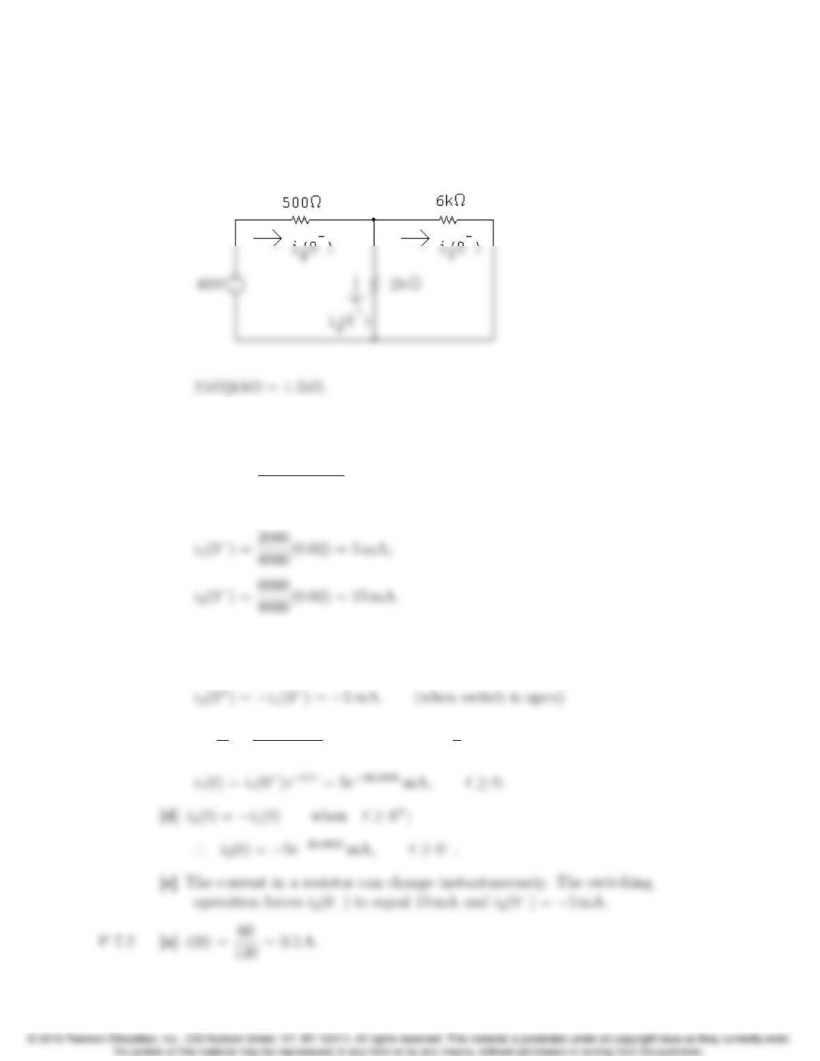
AP 7.12 [a] Use RC circuit analysis to determine the expression for the voltage at the
non-inverting input:
Problems 7–11
[b] Use RC circuit analysis to determine the expression for the voltage at the
non-inverting input:
7–12 CHAPTER 7. Response of First-Order RL and RC Circuits
Problems
P 7.1 [a] t<0:
Find the current from the voltage source by combining the resistors in
series and parallel and using Ohm’s law:
ig(0−)= 40
(1500 + 500) = 20 mA.
Find the branch currents using current division:
[b] The current in an inductor is continuous. Therefore,
i1(0+)=i1(0−) = 5 mA;
[c] τ=L
R=0.4⇥10−3
8⇥103=5⇥10−5s; 1
τ
= 20,000;
Problems 7–13
[c] i=0.5e−500tA,t0;
[d] w(0) = 1
2(0.32)(0.5)2= 40 mJ;
P 7.3 [a] iL(0) = 12
6= 2 A;
[b] iL=2e−t/τ;τ=L
R=1
4s;
7–14 CHAPTER 7. Response of First-Order RL and RC Circuits
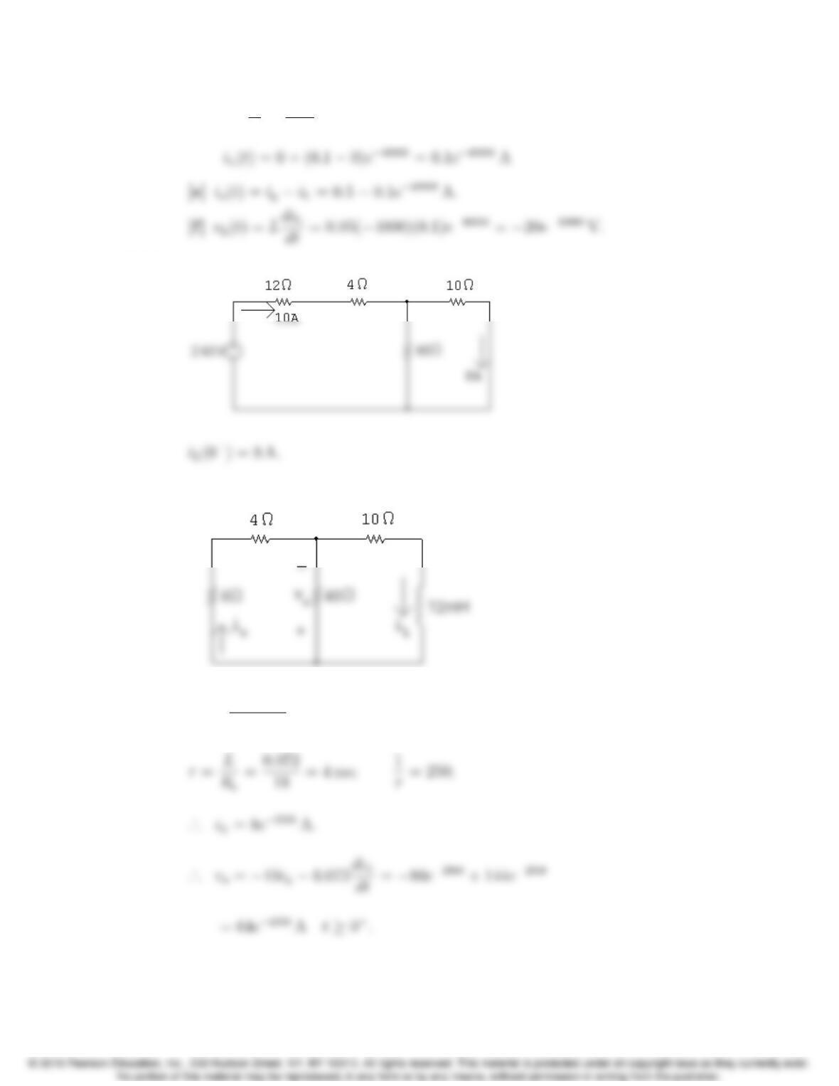
P 7.4 [a] For t=0
−the circuit is:
[b] For t=0
+the circuit is:
[c] As t!1the circuit is:
Problems 7–15
[d] τ=L
R=0.05
200 =0.25 ms;
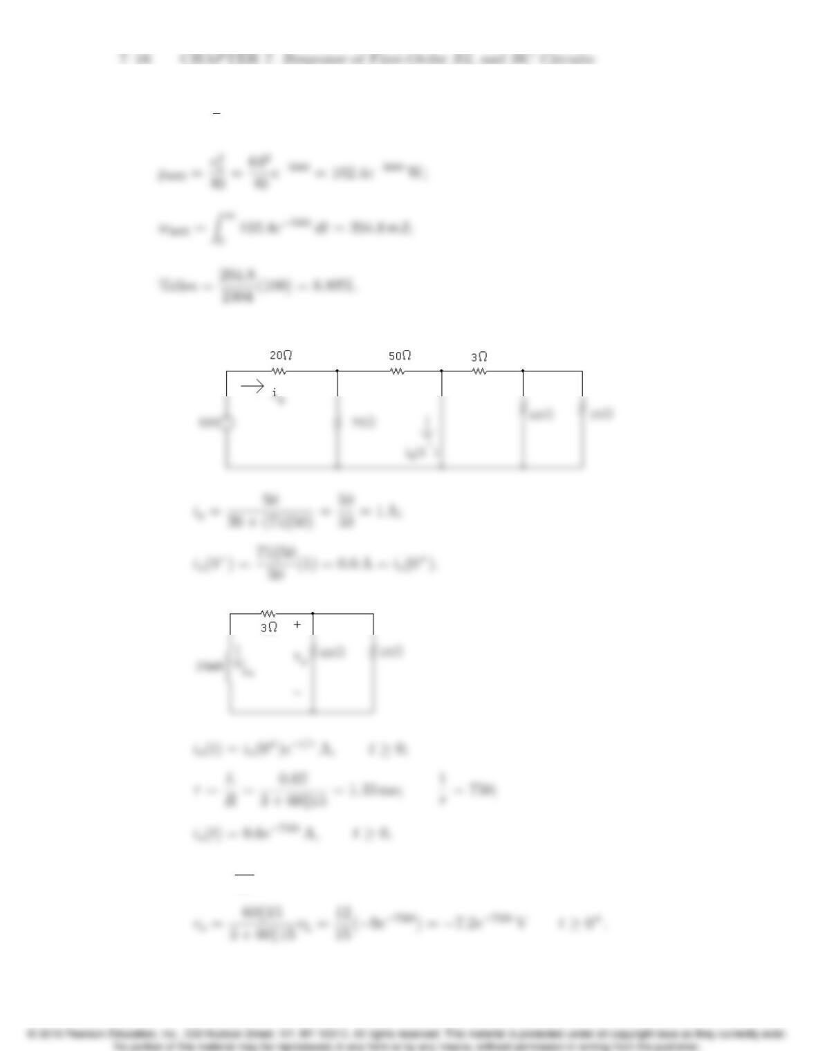
P 7.5 t<0:
t>0:
Re=(10)(40)
50 + 10 = 18 Ω;
P 7.6 w(0) = 1
2(72 ⇥10−3)(8)2= 2304 mJ;
P 7.7 [a] For t<0
For t>0
[b] vL=Ldio
dt =0.02(750)(0.6e−750t)=9e−750tV;
Problems 7–17
P 7.8 [a] v
i=R=400e−5t
10e−5t= 40 Ω.
P 7.9 [a] Note that there are several different possible solutions to this problem,
and the answer to part (c) depends on the value of inductance chosen.
τ
Choose a 10 mH inductor from Appendix H. Then,
[c] w(0) = 1
2LI2
o=1
2(0.01)(0.01)2=0.5µJ;
7–18 CHAPTER 7. Response of First-Order RL and RC Circuits
P 7.10 [a] vo(t)=vo(0+)e−t/τ;
[b] vo(0+)=10iL(0+)=10(1/10)(30 ⇥10−3)=30 mV;
P 7.11 w(0) = 1
2(30 ⇥10−3)(32) = 135 mJ;
Problems 7–19
P 7.12 [a] w(0) = 1
2LI2
g.
P 7.13 [a] t<0
7–20 CHAPTER 7. Response of First-Order RL and RC Circuits
t>0:
wdiss =Zt
00.10e−8000xdx = 12.5⇥10−6[1 e−8000t] J;
[b] wdiss(total) = 75(1 e−8000t)µJ;