Problems 6–21
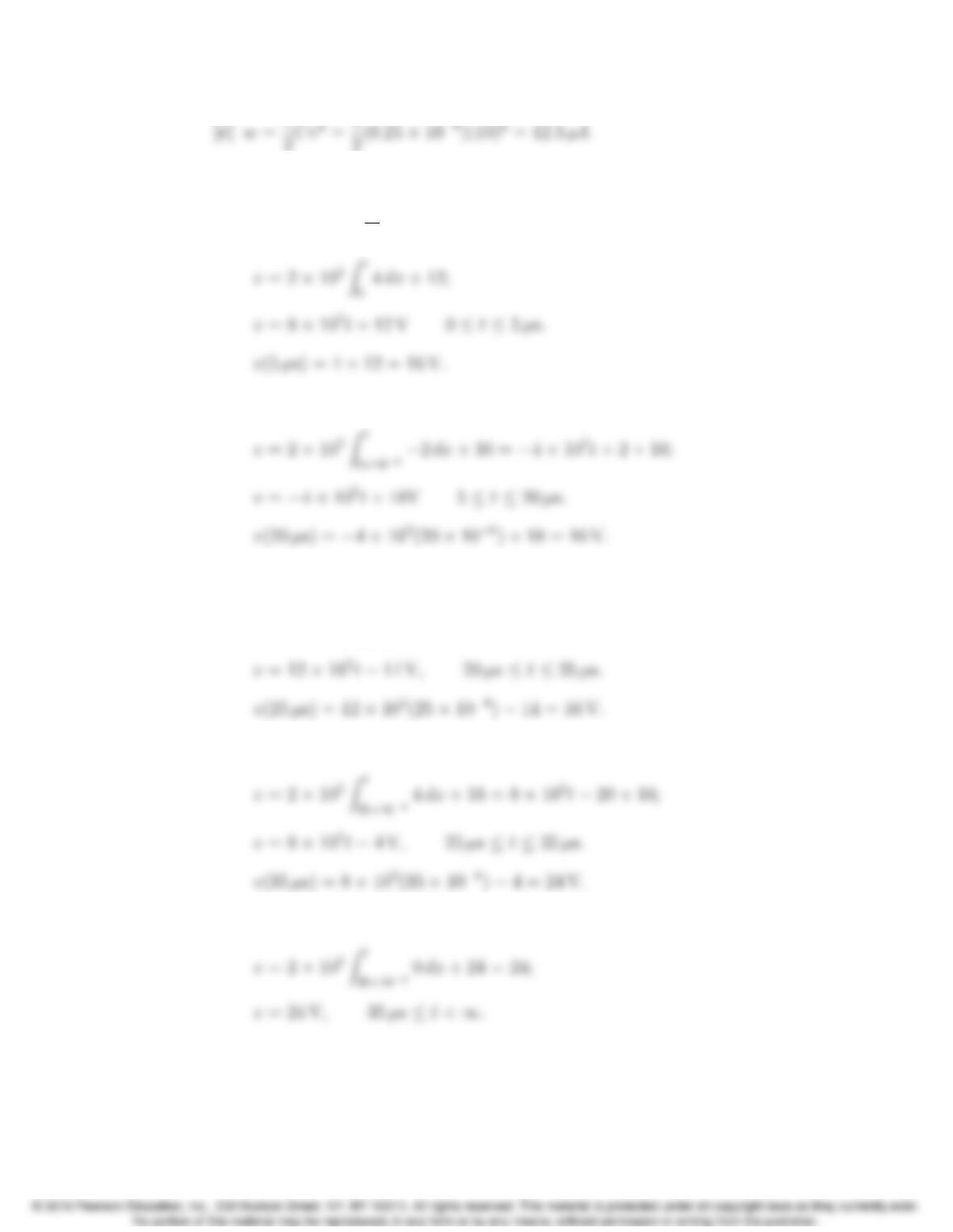
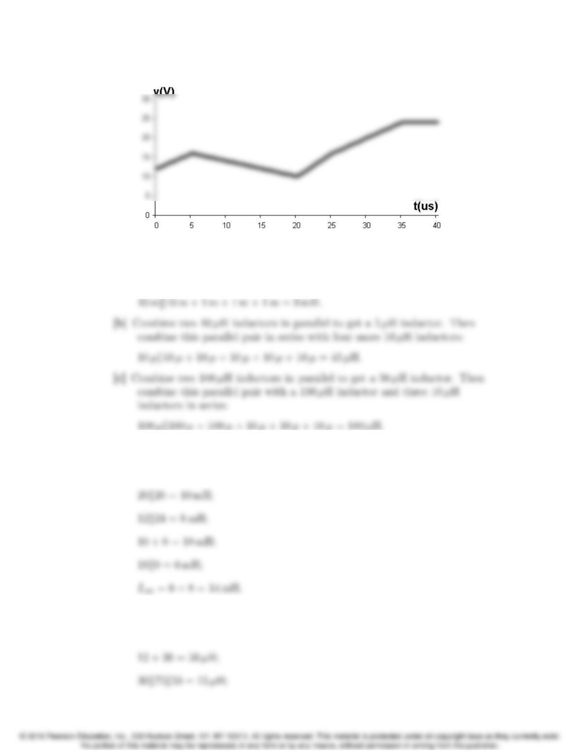
P 6.21 [a] 0t5µs:
C=5µF1
C=2⇥105;
[b] 5µst20 µs:
[c] 20 µst25 µs:
v=2⇥105Zt
20⇥10−66dx + 10 = 12 ⇥105t24 + 10;
[d] 25 µst35 µs:
[e] 35 µst<1;
6–22 CHAPTER 6. Inductance, Capacitance, and Mutual Inductance
[f]
P 6.22 [a] Combine two 10 mH inductors in parallel to get a 5 mH equivalent
inductor. Then combine this parallel pair in series with three 1 mH
inductors:
P 6.23 [a] 15k30 = 10 mH;
10 + 10 = 20 mH;
[b] 12 + 18 = 30 µH;
30k20 = 12 µH;
Problems 6–23
[b]
[c]
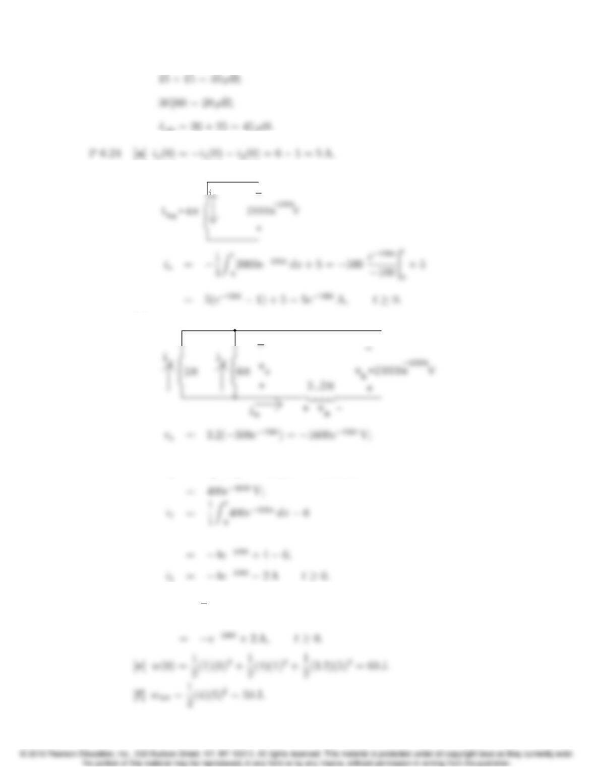
vc=va+vb=1600e100t+ 2000e100t
[d] i2=1
4Zt
0400e100xdx +1
6–24 CHAPTER 6. Inductance, Capacitance, and Mutual Inductance
P 6.25 vb= 2000e100tV;
w=Zt
0104e200xdx = 10,000e200x
200
t
0
= 50(1 e200t) W;
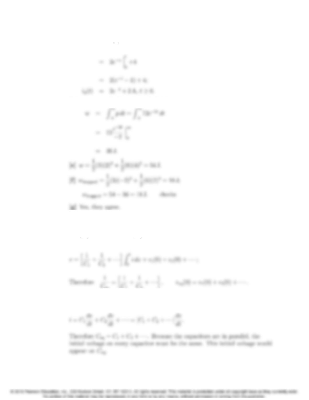
P 6.26 [a]
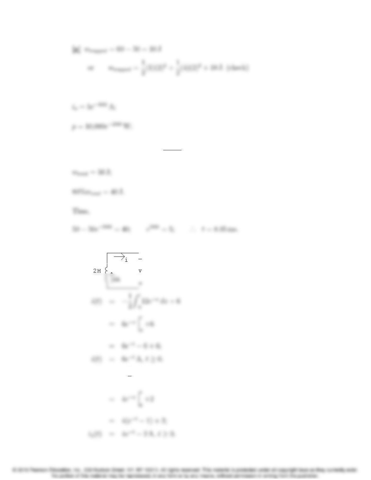
[b] i1(t)=1
3Zt
012exdx +2
Problems 6–25
[c] i2(t)=1
6Zt
012exdx +4
[d] p=vi = (12et)(6et)=72e2tW:
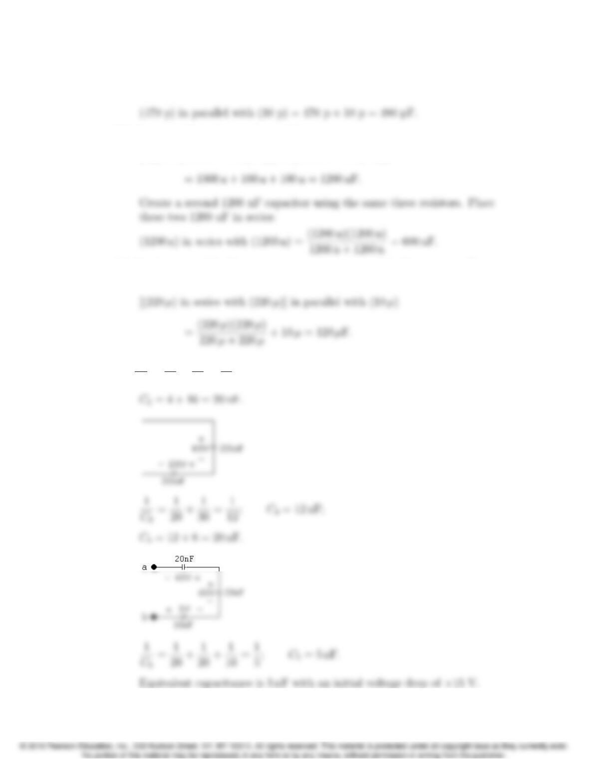
P 6.27 From Figure 6.17(a) we have
v=1
C1Zt
0idx+v1(0) + 1
C2Zt
0idx+v2(0) + ···;
P 6.28 From Fig. 6.18(a)
6–26 CHAPTER 6. Inductance, Capacitance, and Mutual Inductance
P 6.29 [a] Combine a 470 pF capacitor and a 10 pF capacitor in parallel to get a 480
pF capacitor:
[b] Create a 1200 nF capacitor as follows:
(1 µ) in parallel with (0.1µ) in parallel with (0.1µ)
[c] Combine two 220 µF capacitors in series to get a 110 µF capacitor. Then
combine the series pair in parallel with a 10 µF capacitor to get 120 µF:
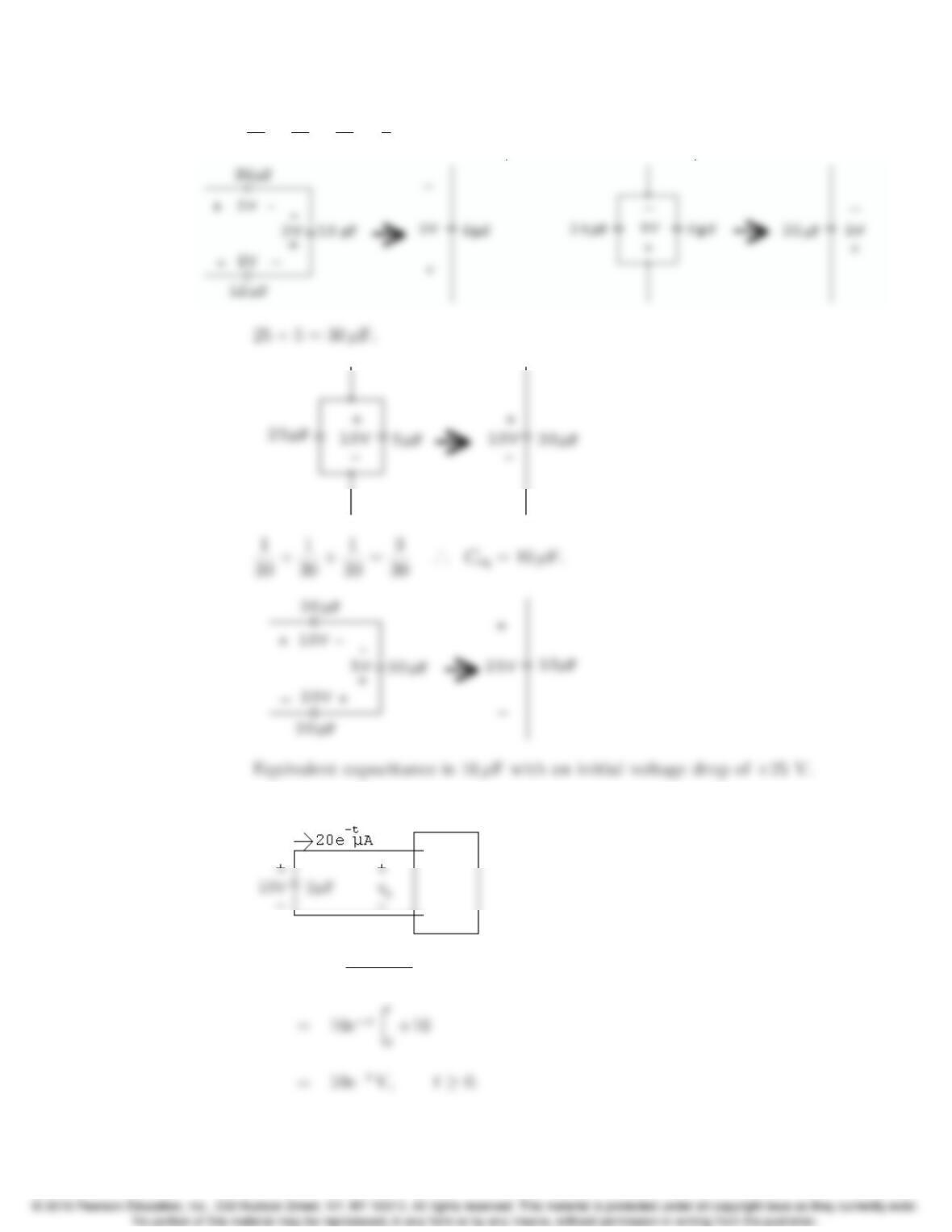
P 6.30 [a] 1
C1
=1
48 +1
24 =1
16;C1= 16 nF;
Problems 6–27
[b] 1
36 +1
18 +1
12 =1
6·
.. C
eq =6µF 24 + 6 = 30 µF.
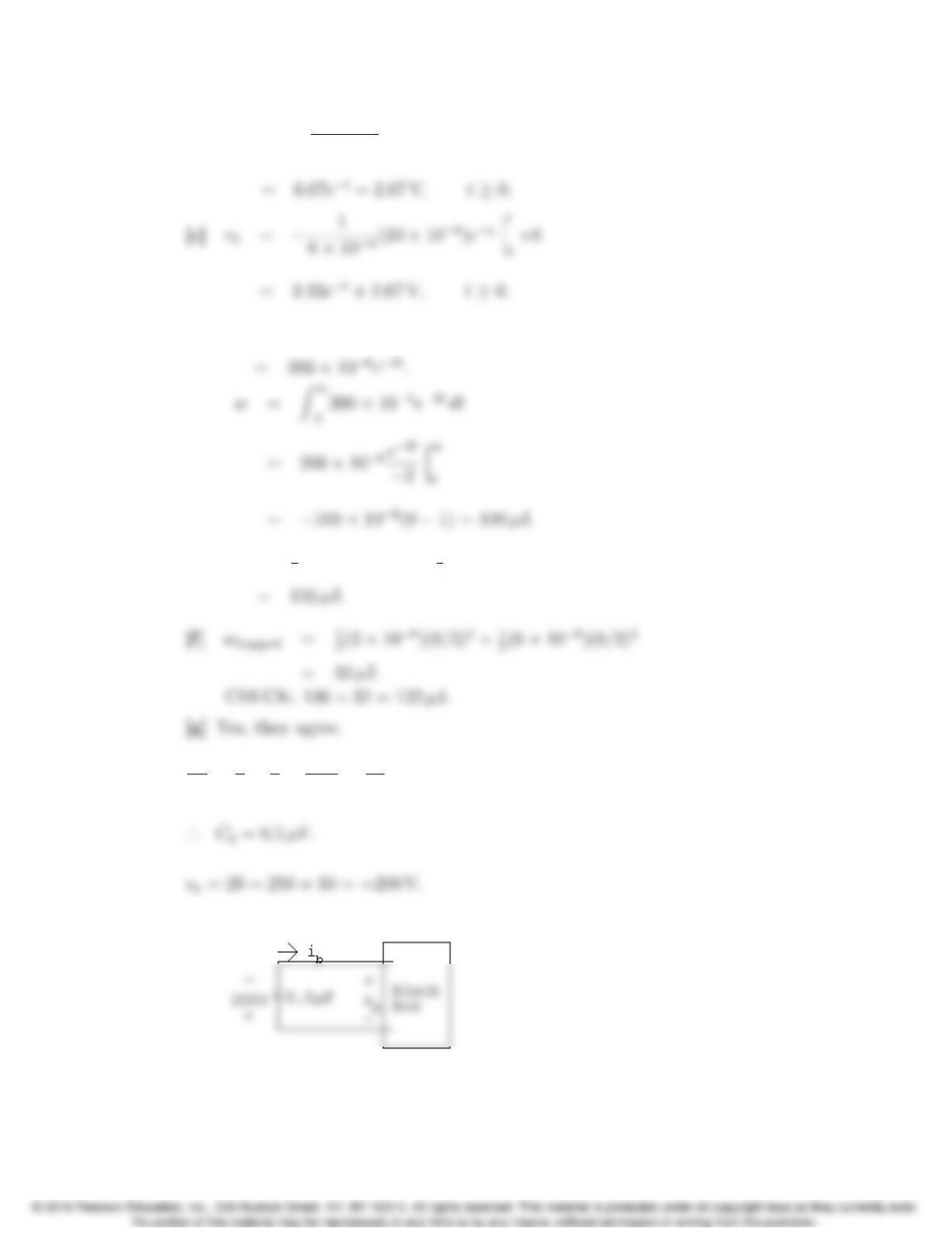
P 6.31 [a]
vo=1
2⇥106Zt
020 ⇥106exdx +10
6–28 CHAPTER 6. Inductance, Capacitance, and Mutual Inductance
[b] v1=1
3⇥106(20 ⇥106)ex
t
0
+4
[d] p=vi = (10et)(20 ⇥106)et
[e] w=1
2(3 ⇥106)(4)2+1
2(6 ⇥109)(6)2
P 6.32 1
Ce
=1
1+1
5+1
1.25 =10
5= 2;
[a]
Problems 6–29
vb=106
0.5Zt
05⇥103e50xdx 200
[b] va=106
5Zt
05⇥103e50xdx 20
[c] vc=106
1.25Zt
05⇥103e50xdx 30
[d] vd=10
6Zt
05⇥103e50xdx + 250
[e] i1=0.2⇥106d
dt [100e50t+ 150]
P 6.33 [a] w(0) = 1
6–30 CHAPTER 6. Inductance, Capacitance, and Mutual Inductance
[e] w=Zt
0(0.005e50x)(200e50x)dx =Zt
0e100xdx
P 6.34 vc=1
0.625 ⇥106✓Zt
01.5e16,000xdx Zt
00.5e4000xdx◆50
P 6.35 dio
P 6.36 [a] Rearrange by organizing the equations by di1/dt,i1,di2/dt,i2and transfer
the igterms to the right hand side of the equations. We get
Problems 6–31
[b] From the given solutions we have
di1
dt =320e5t+ 272e4t;
Thus,
4di1
dt =1280e5t+ 1088e4t;
Thus,
1280e5t+ 1088e4t+ 100 + 1600e5t1700e4t2080e5t
+(1600 1280 2080 + 1040)e5t?
= 80 720e5t;
6–32 CHAPTER 6. Inductance, Capacitance, and Mutual Inductance
2560e5t2176e4t80 1280e5t+ 1360e4t+ 4160e5t3264e4t
P 6.37 [a] vab =L1
di
dt +L2
di
dt +Mdi
dt +Mdi
dt =(L1+L2+2M)di
dt.
P 6.38 [a] vab =L1
d(i1i2)
dt +Mdi2
dt ;
Collecting coefficients of [di1/dt] and [di2/dt],the two mesh-current
equations become
and
Solving for [di1/dt] gives
from which we have
[b] If the magnetic polarity of coil 2 is reversed, the sign of Mreverses,
therefore
Problems 6–33
P 6.39 [a] vg=5(igi1) + 20(i2i1)+60i2
[c] pdev =vgig
[e] i1(1) = 4 A; i2(1) = 1 A; ig(1) = 16 A;
p5Ω= (16 4)2(5) = 720 W;
P 6.40 [a] Yes, using KVL around the lower right loop
[b] vo= 20(1 52e5t+51e4t464e5t+68e4t)+
[c] vo=L2
d
dt(igi2)+Mdi1
dt
6–34 CHAPTER 6. Inductance, Capacitance, and Mutual Inductance
P 6.41 [a] 0.5dig
dt +0.2di2
dt +10i2= 0;
[c] v1=5
dig
dt +0.5di2
dt
P 6.42 When the switch is opened the induced voltage is negative at the dotted
terminal. Since the voltmeter kicks downscale, the induced voltage across the
P 6.43 [a] Dot terminal 2; the flux is up in coil 1-2, and right-to-left in coil 3-4.
P 6.44 [a] 1
k2=✓1+P11
P12 ◆✓1+P22
P12 ◆=✓1+P11
P21 ◆✓1+P22
P12 ◆.
Problems 6–35
Therefore
Now note that
and similarly
It follows that
and
therefore k<1.
P 6.45 [a] w= (0.5)L1i2
1+ (0.5)L2i2
2+Mi1i2;
P 6.46 [a] M=1.0q(18)(32) = 24 mH,i
1=6A.
6–36 CHAPTER 6. Inductance, Capacitance, and Mutual Inductance
P 6.47 [a] L2= M2
k2L1!=(0.09)2
(0.75)2(0.288) = 50 mH;
[c] L1
L2
=N2
1P1
N2
2P2
=✓N1
N2◆2
;
P 6.49 P1=L1
N2
1
= 2 nWb/A; P2=L2
N2
2
= 2 nWb/A; M=kqL1L2= 180 µH;
P 6.50 [a] L1=N2
1P1;P1=72 ⇥103
6.25 ⇥104= 1152 nWb/A;
Problems 6–37
[d] φ22
φ12
=P22
P12
=P2P
12
P12
=P2
P12 1;
P 6.51 When the touchscreen in the mutual-capacitance design is touched at the point
x, y, the touch capacitance Ctis present in series with the mutual capacitance
P 6.52 [a] The self-capacitance and the touch capacitance are effectively connected in
parallel. Therefore, the capacitance at the x-grid electrode closest to the
touch point with respect to ground is
[b] The mutual-capacitance and the touch capacitance are effectively
connected in series. Therefore, the mutual capacitance between the
[c] In the self-capacitance design, touching the screen increases the
capacitance being measured at the point of touch. For example, in part
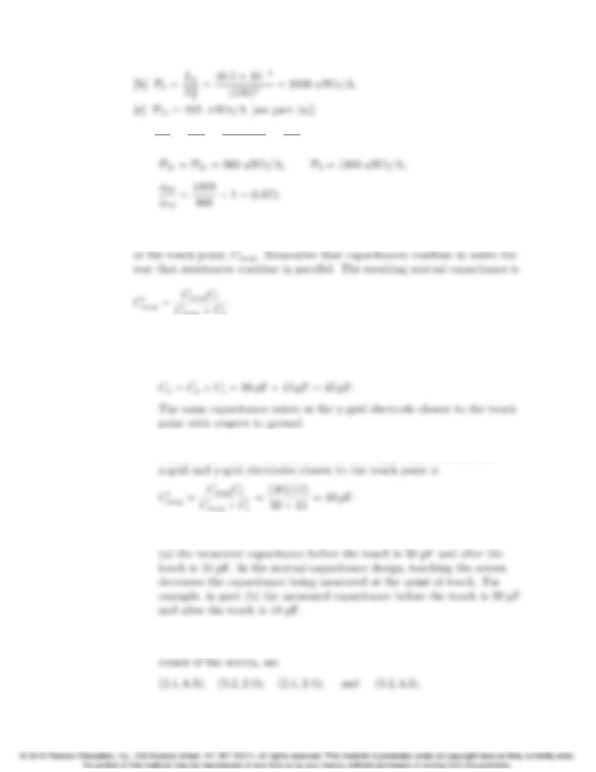
P 6.53 [a] The four touch points identified are the two actual touch points and two
ghost touch points. Their coordinates, in inches from the upper left
6–38 CHAPTER 6. Inductance, Capacitance, and Mutual Inductance
These four coordinates identify a rectangle within the screen, shown
below.
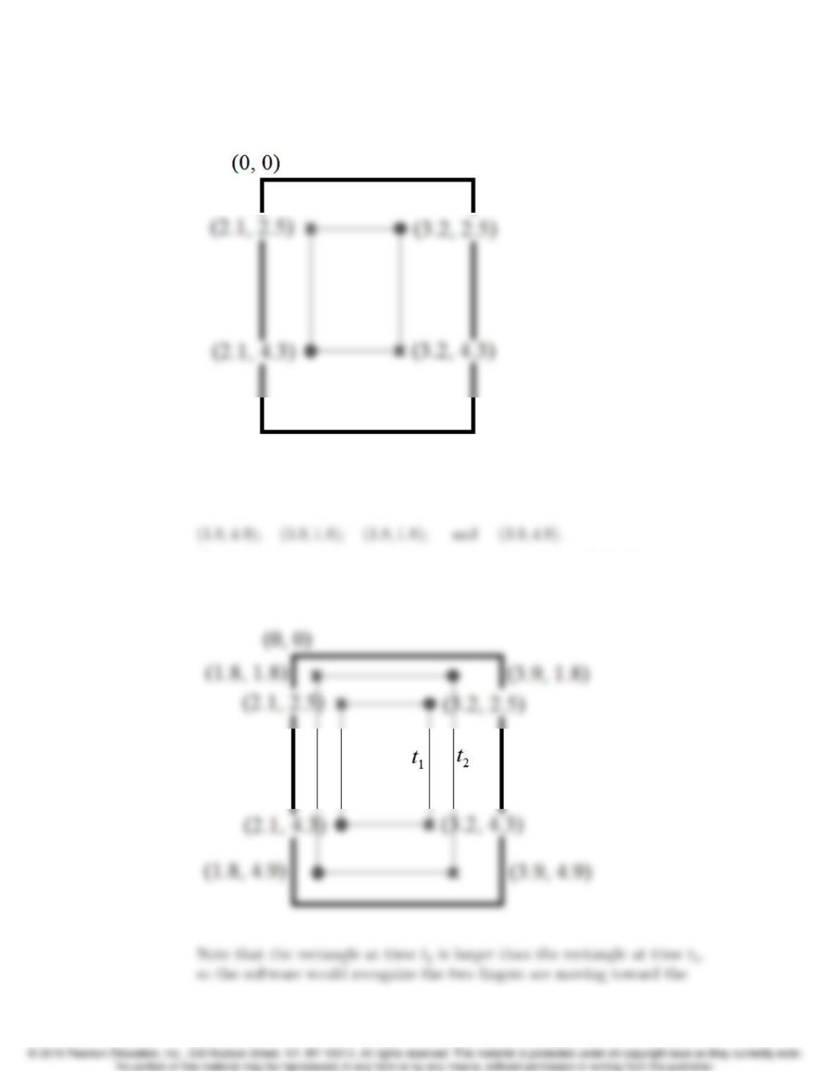
[b] The touch points identified at time t1are those listed in part (a). The
touch points recognized at time t2are
The first two coordinates are the actual touch points and the last two
coordinates are the associated ghost points. Again, the four coordinates
identify a rectangle at time t2, as shown here:
Problems 6–39
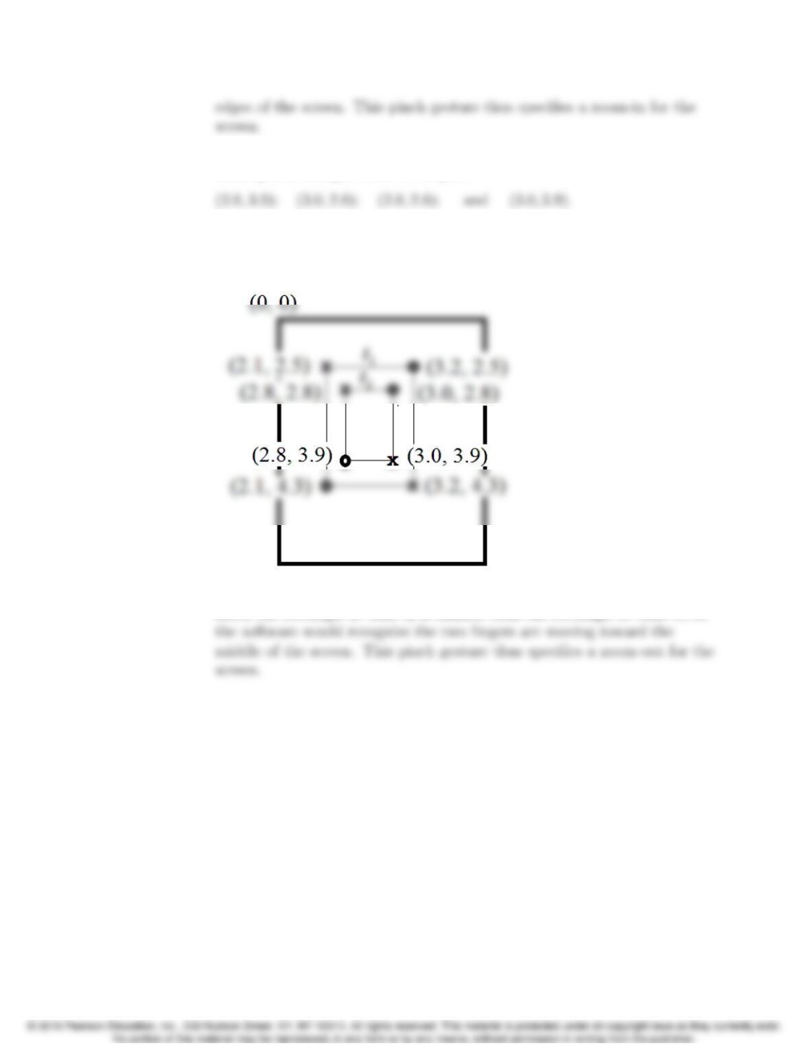
[c] The touch points identified at time t1are those listed in part (a). The
touch points recognized at time t2are
The first two coordinates are the actual touch points and the last two
coordinates are the associated ghost points. Again, the four coordinates
identify a rectangle at time t2, as shown here:
Here, the rectangle at time t2is smaller than the rectangle at time t1,so