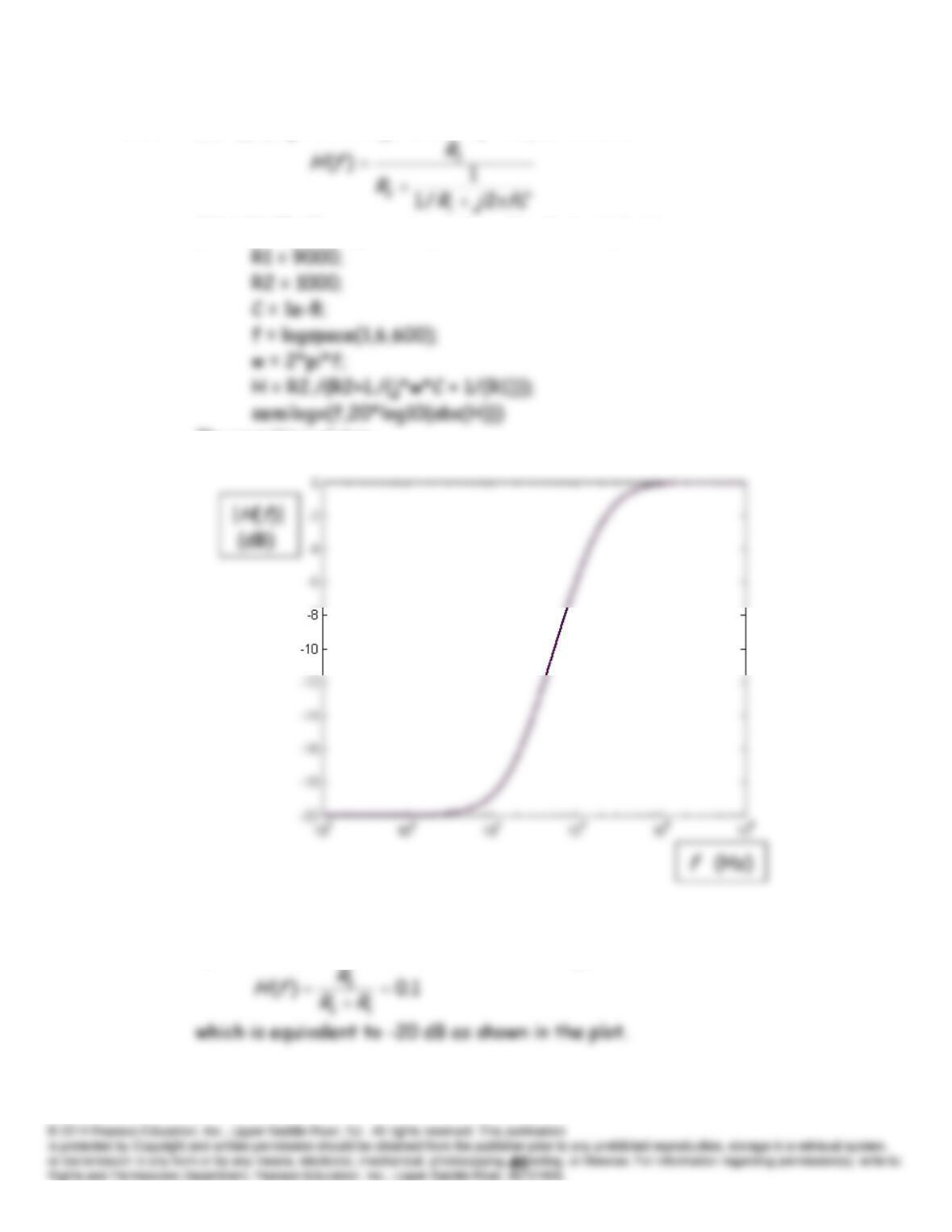
P6.91 (a) Applying the voltage-division principle, we have
(b) A MATLAB program to produce the desired plot is
The resulting plot is
(c) At very low frequencies, with the capacitance considered to be an
open circuit, we have a two-resistance voltage divider and
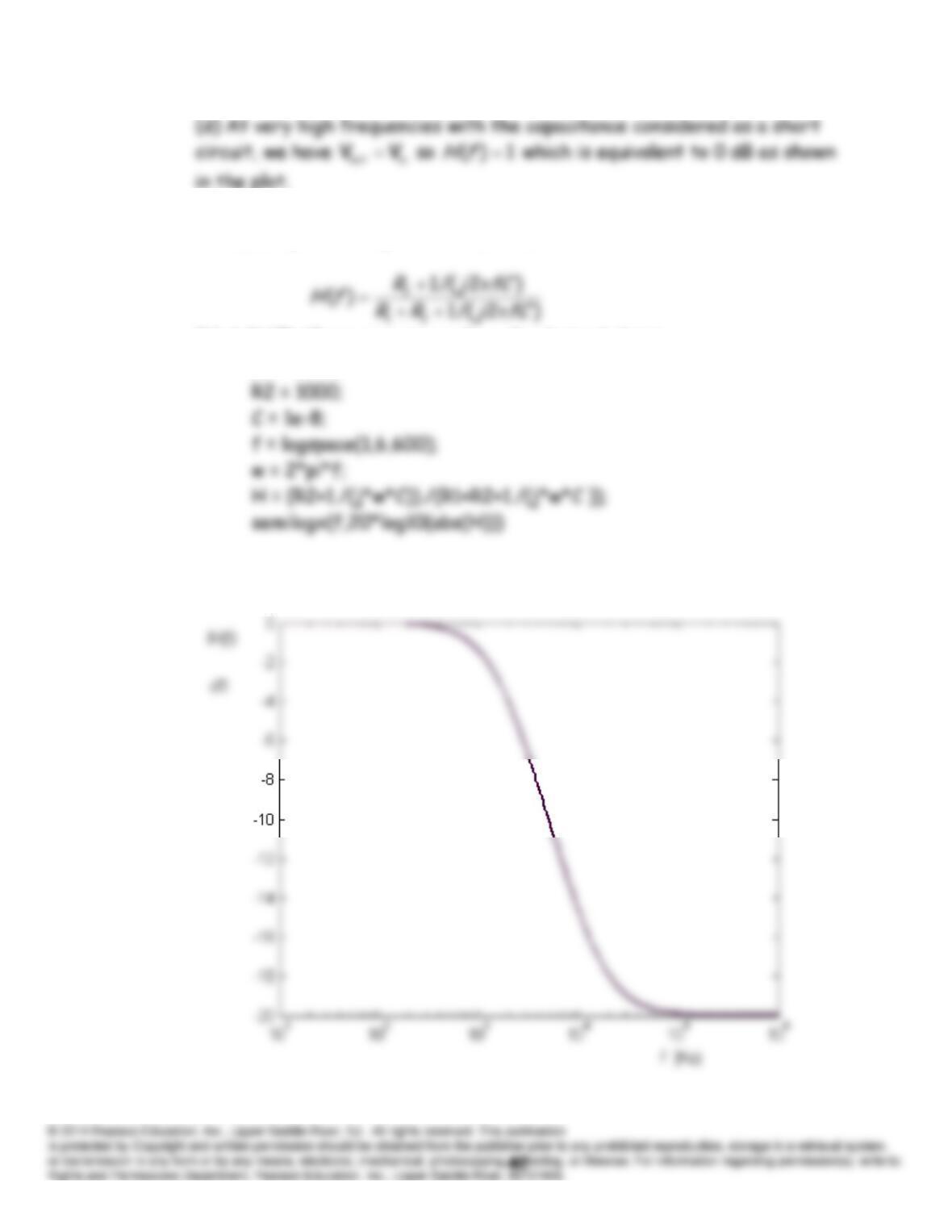
P6.92 (a) Applying the voltage-division principle, we have
(b) A MATLAB program to produce the desired plot is
R1 = 9000;
The resulting plot is
(c) At very low frequencies, with the capacitance considered to be an
(d) At very high frequencies with the capacitance considered as a short
P6.93 (a and b)
R
1 and
C
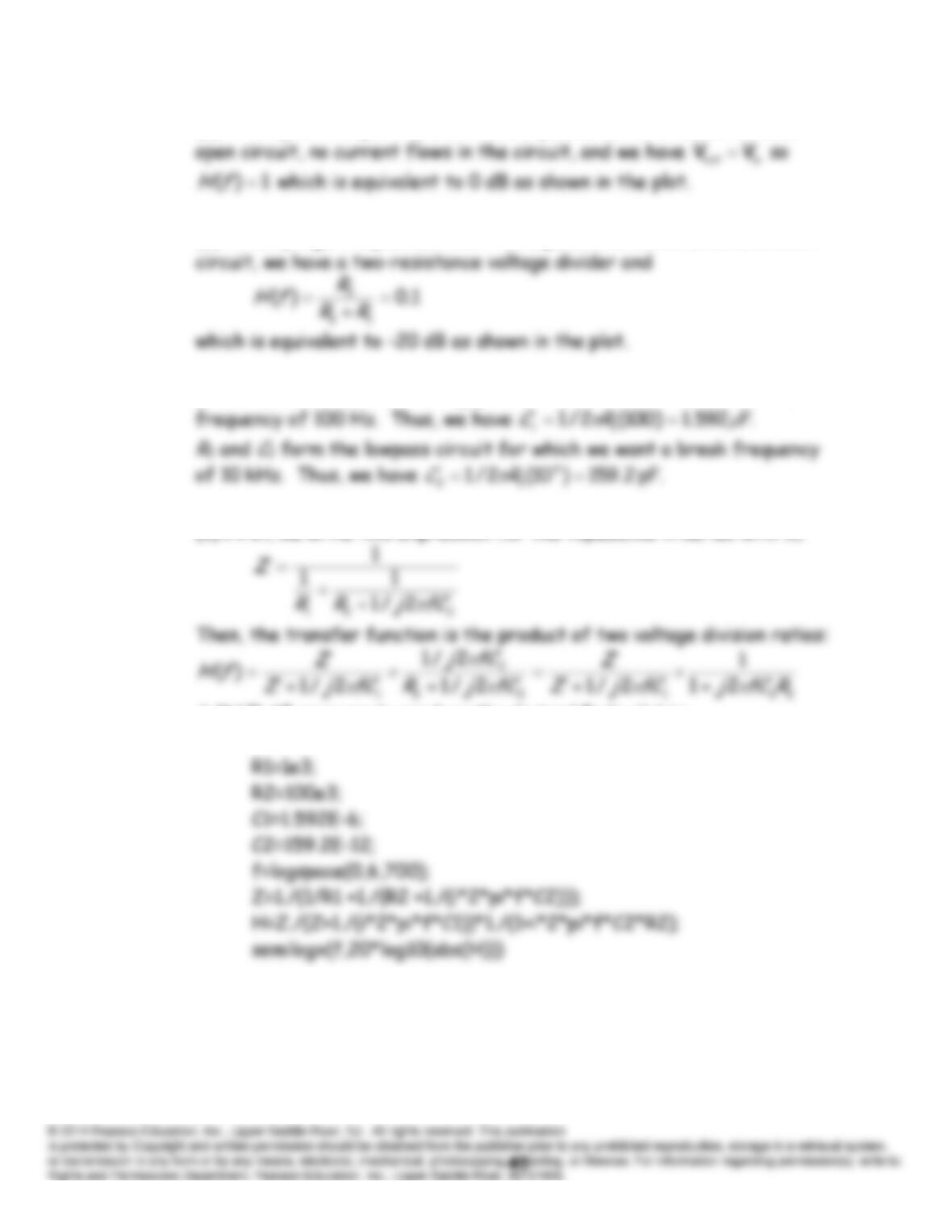
1 form the highpass circuit for which we want a break
(c) First, we write this expression for the impedance in series with
C
A MATLAB program to produce the desired Bode plot is:
The resulting Bode plot is:
P6.94 (a and b)
R
1 and
C
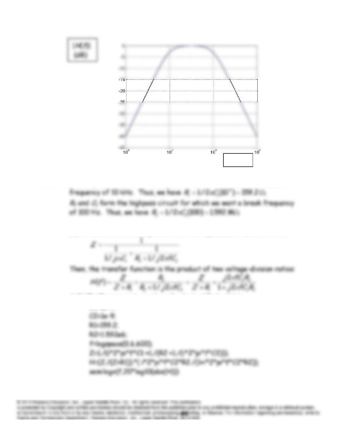
1 form the lowpass circuit for which we want a break
(c) First, we write this expression for the impedance in series with
R
1:
A MATLAB program to produce the desired Bode plot is:
C1=1e-7;
The resulting Bode plot is:
f
(Hz)
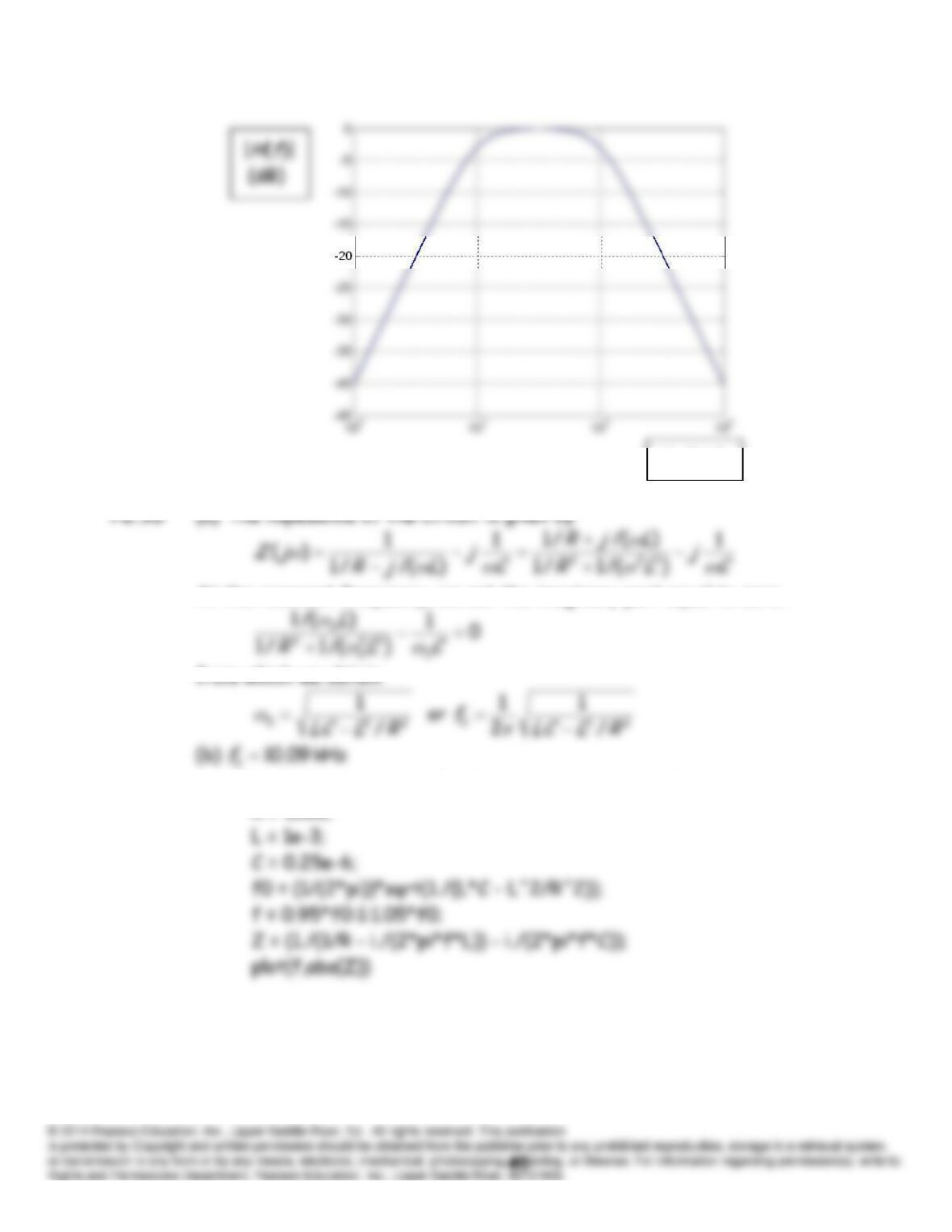
At the resonant frequency, we set the imaginary part equal to zero.
(c) A MATLAB program to plot the impedance magnitude is
R = 1000;
The resulting plot is:
f
(Hz)
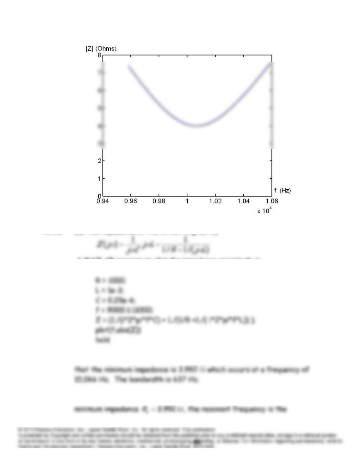
P6.96 (a) The impedance of the circuit is given by
A MATLAB program to plot the impedance magnitude is
(b) Looking through the values for abs(Z) computed by MATLAB, we find
(c) For a series circuit with these parameters, the resistance equals the
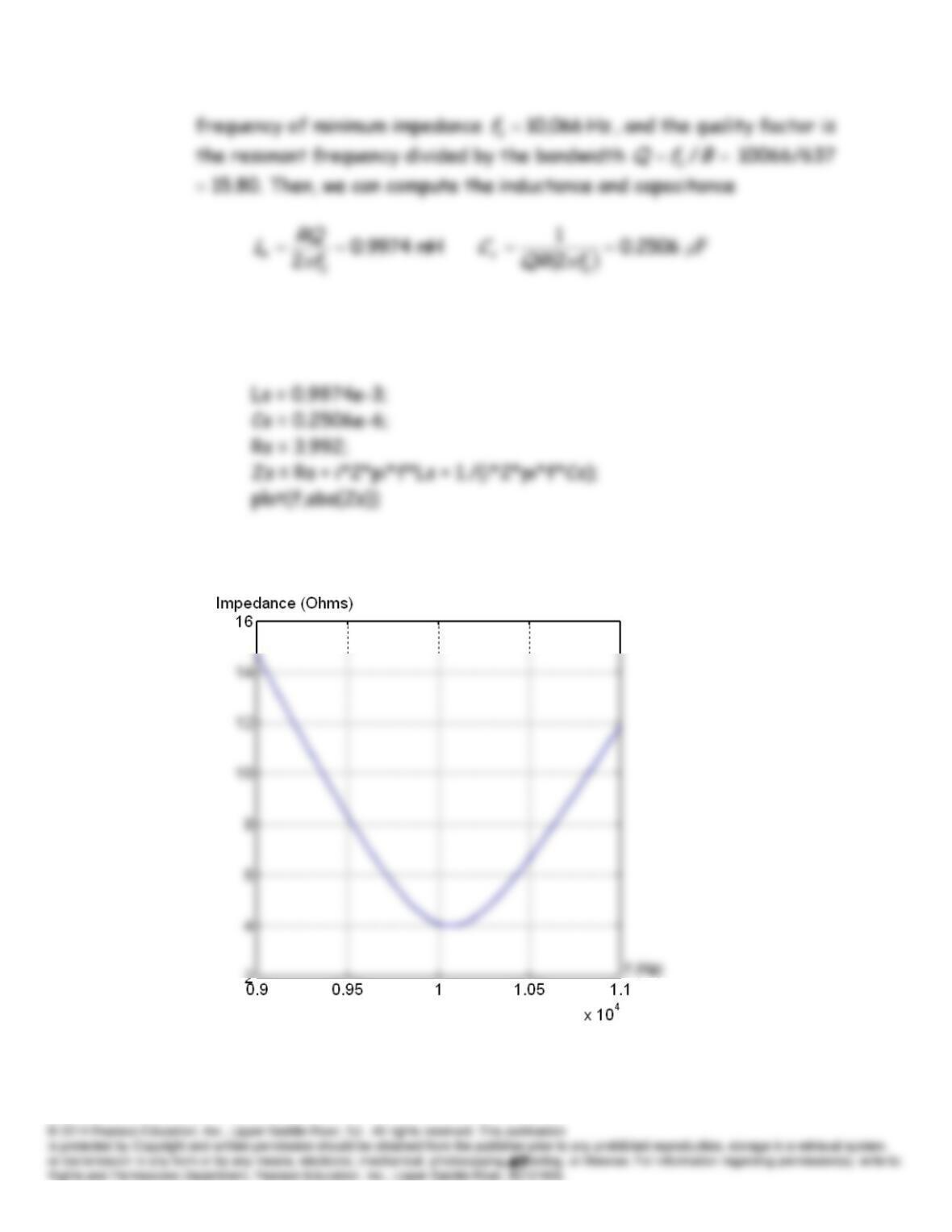
(d) After executing the program of part (a) if we use the following
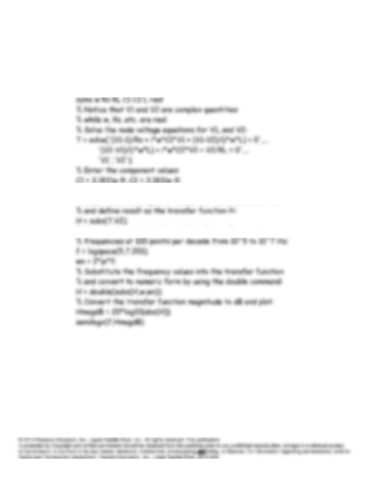
commands, we get the plot for the series circuit.
The impedances have virtually the same plot:
P6.97 The MATLAB commands are:
% Construct the symbolic objects that appear in the circuit:
syms V1 V2
L = 15.915e-6; Rs = 50; RL = 50;
% Substitute the component values into the solution for V2
% Set up a row matrix of logarithmically equally spaced
The resulting plot is:
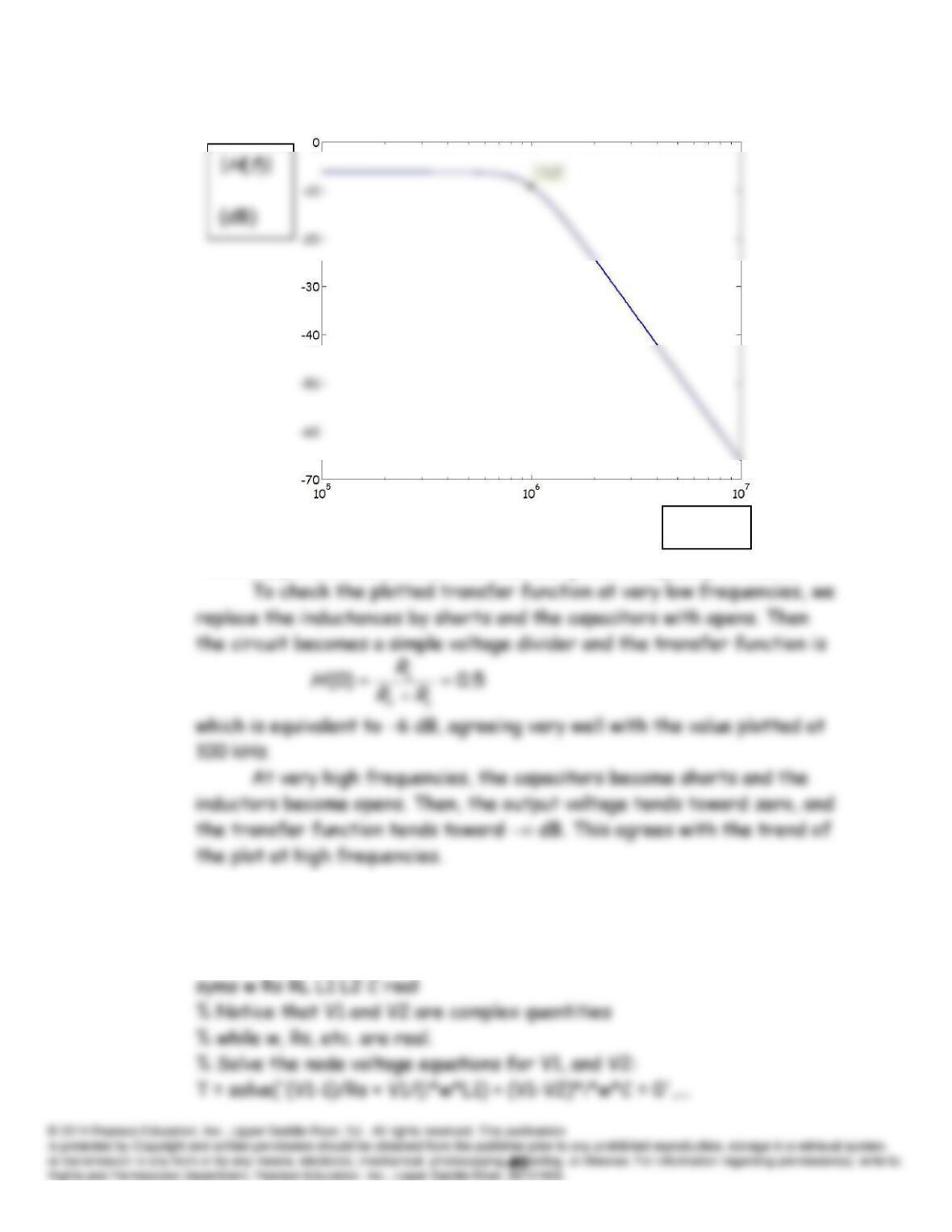
From the plot, we determine that the half-power frequency is 1 MHz.
P6.98 The MATLAB commands are:
% Construct the symbolic objects that appear in the circuit:
syms V1 V2
f
(Hz)
C=1.5915e-9; Rs = 50; RL = 50;
% Substitute the component values into the solution for V2
% and define result as the transfer function H:
H = subs(T.V2);
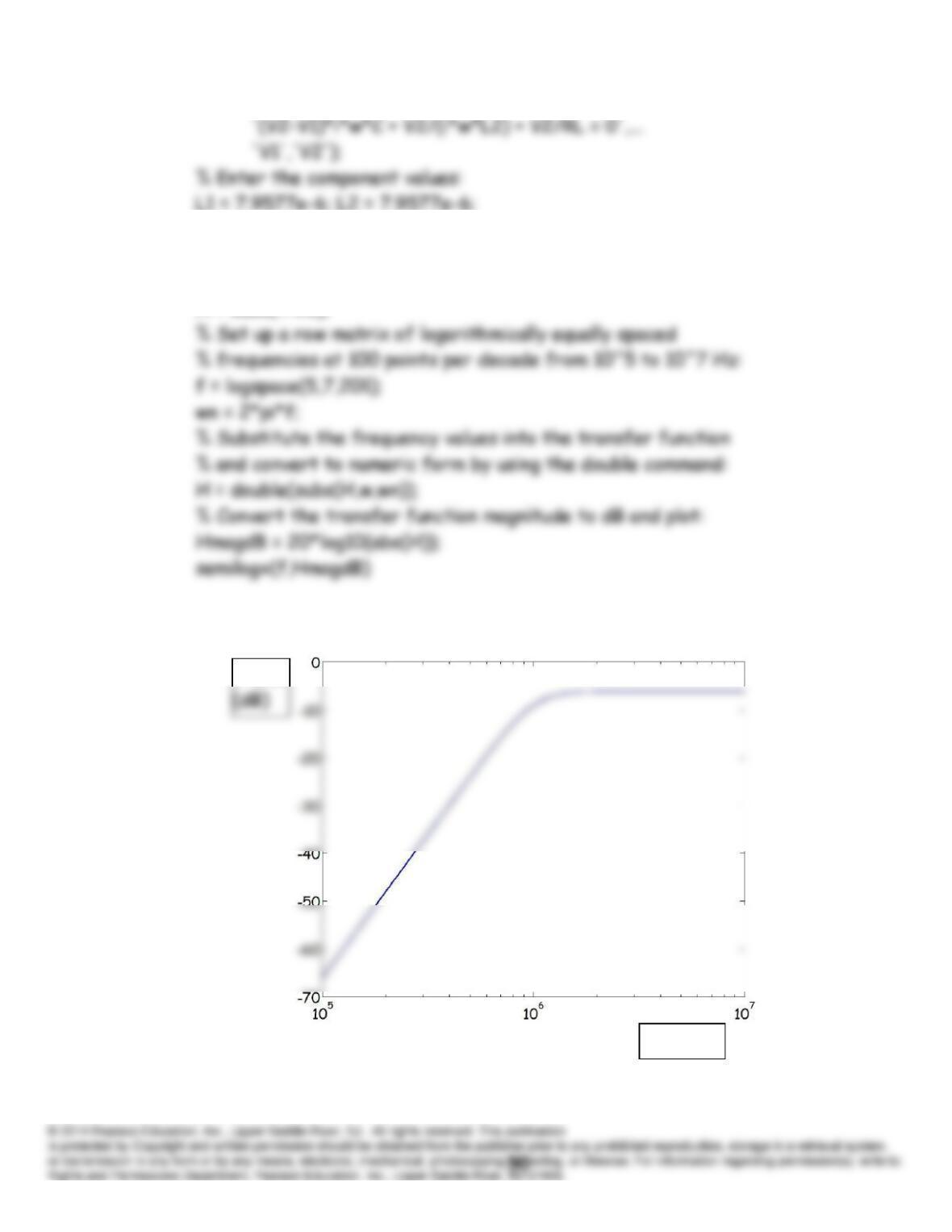
The resulting plot is:
|
H
(
f
)|
f
(Hz)
5.0)0(
L
s
L
RR
R
H
which is equivalent to 6 dB, agreeing very well with the value plotted at
P6.99 (a) The admittance of the circuit is given by
LjR
1
from which we obtain
(c) A MATLAB program to plot the impedance magnitude is
R = 1;
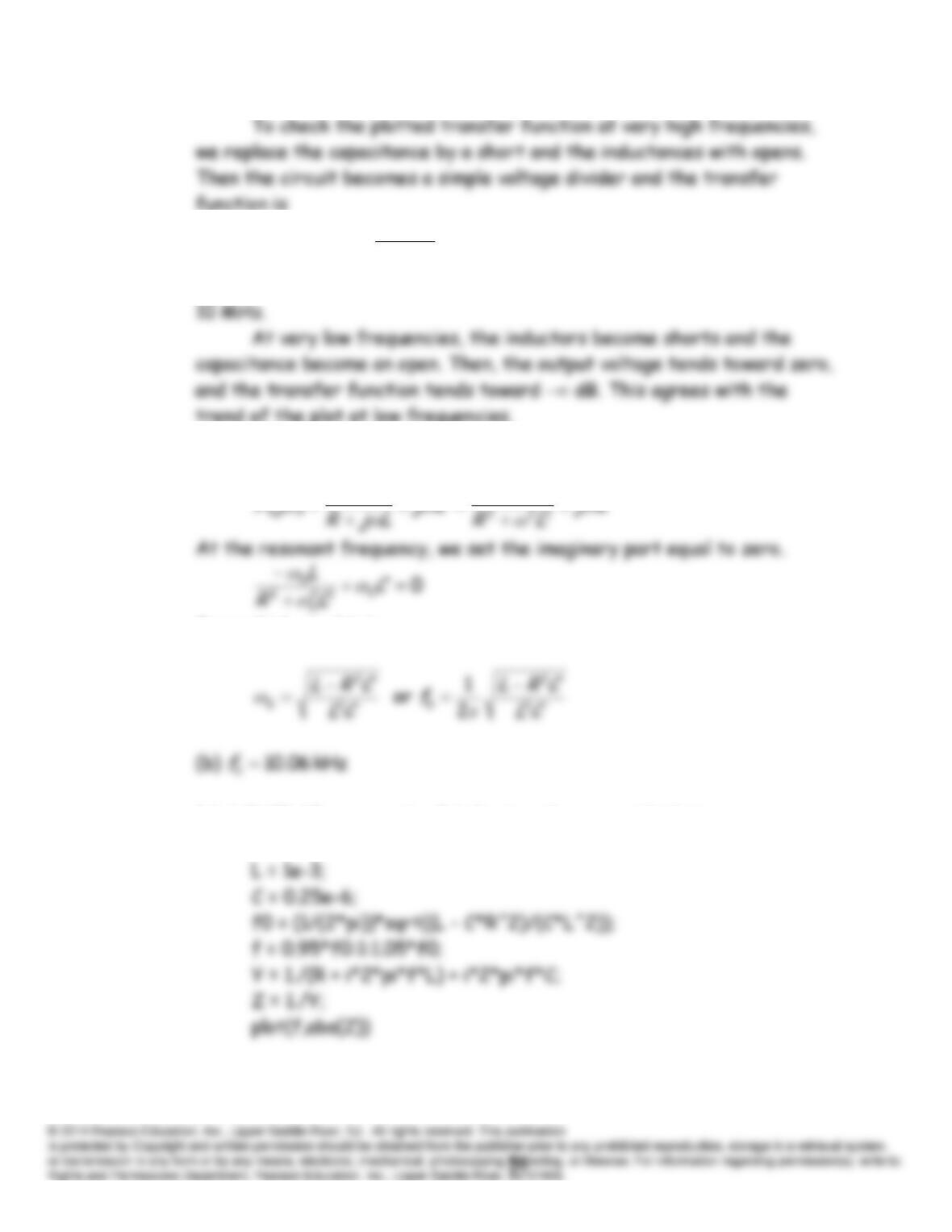
The resulting plot is:
P6.100 (a) Applying the voltage-division principle, we have
(b) A MATLAB program to produce the desired plot is
R = 10;
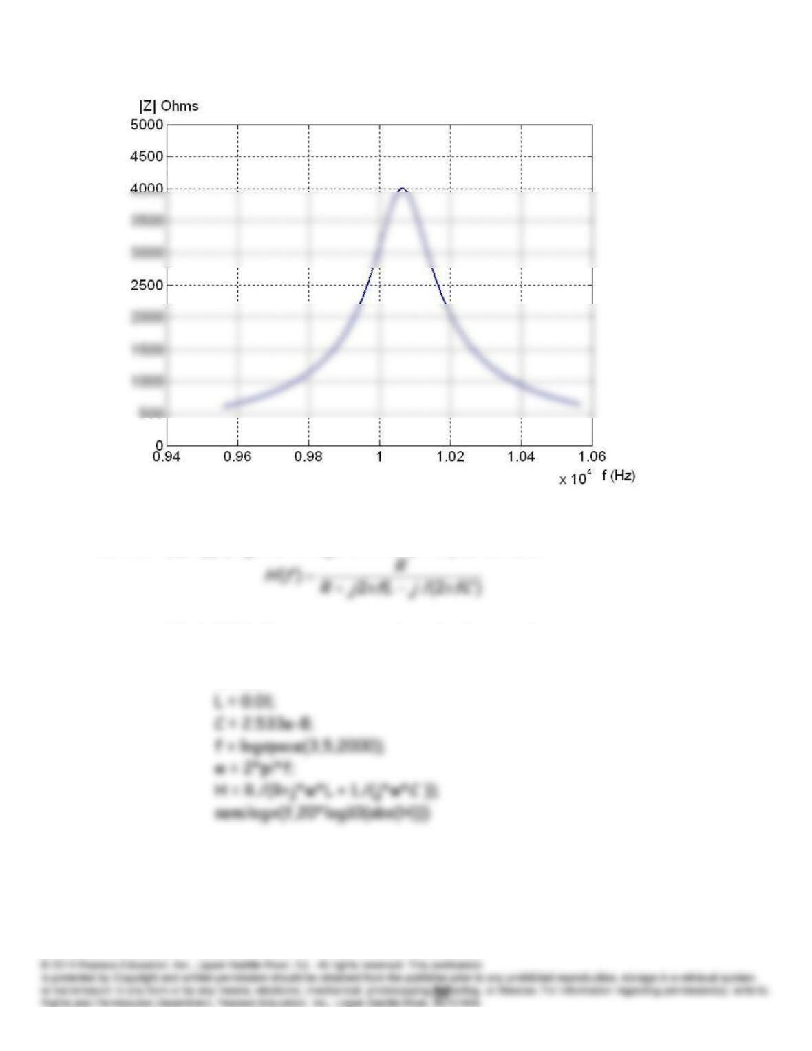
The resulting plot is