120cos200
ttvcn
ca
P5.90 We are given
15400cos150
ttvan
(a) By inspection,
Hz. 200 have we and 4002
ff
P5.91*
P5.92*
rmsV 1.76244033
VV
1
1
Y
CjR
Z
P5.93 Total power flow in a balanced system is constant with time. For a single
phase system the power flow pulsates. Reduced vibration in generators
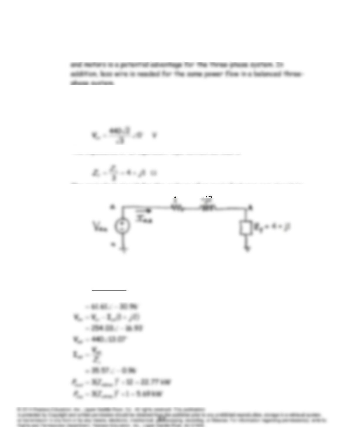
P5.94 This is a positive sequence source. The phasor diagram is shown in Figure
5.41 in the book. Thus, we have
The impedance of an equivalent wye-connected load is
The equivalent circuit for the
a
-phase of an equivalent wye-wye circuit is:
Thus, the line current is
21
Y
an
aA
Zj
V
I
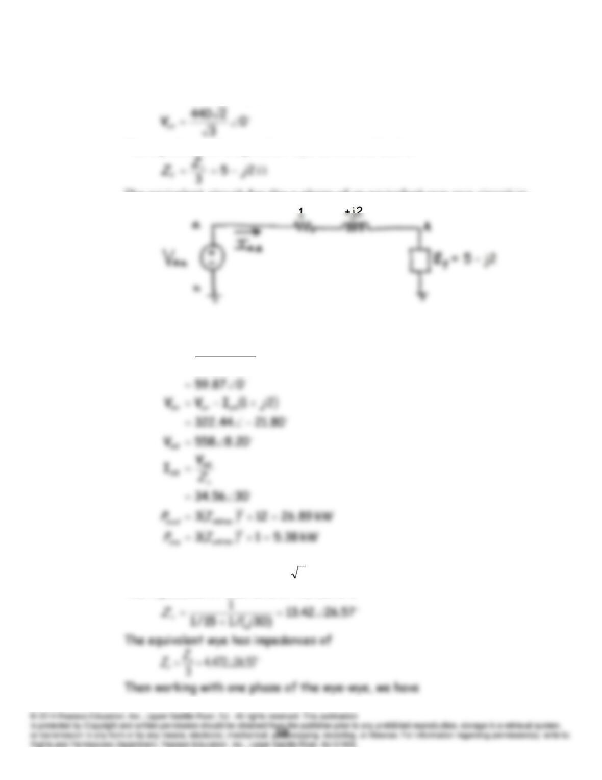
P5.95* This is a positive sequence source. The phasor diagram is shown in Figure
5.41 in the book. Thus, we have:
The impedance of a equivalent wye-connected load is
The equivalent circuit for the a-phase of an equivalent wye-wye circuit is:
Thus, the line current is:
21
Y
an
aA
Zj
V
I
P5.96 The line-to-line voltage is
rms.V 4803277
The impedance of each arm of the delta is
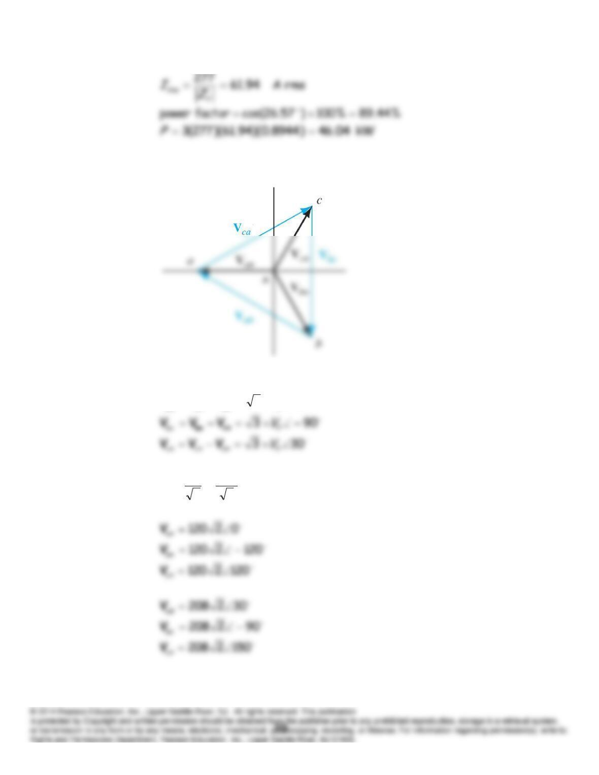
P5.97 The phasor diagram is:
1503
Y
bn
an
ab
V
VVV
P5.98
rmsV 120
3
208
3
L
Y
V
V
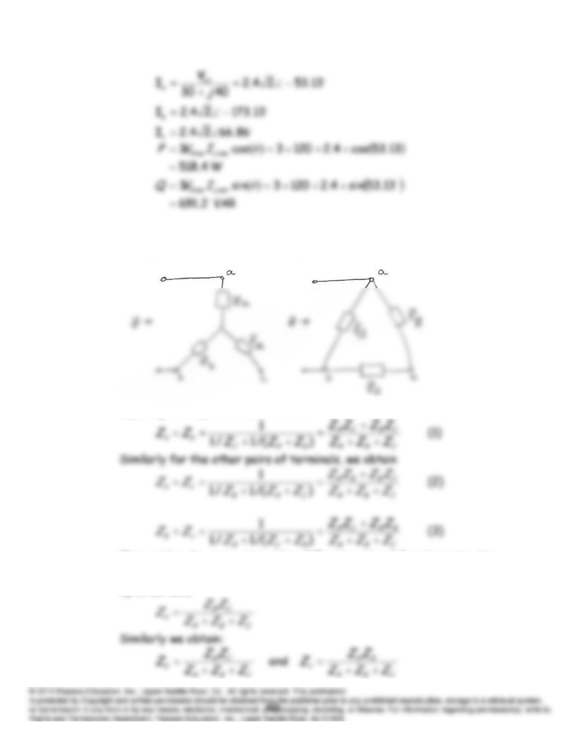
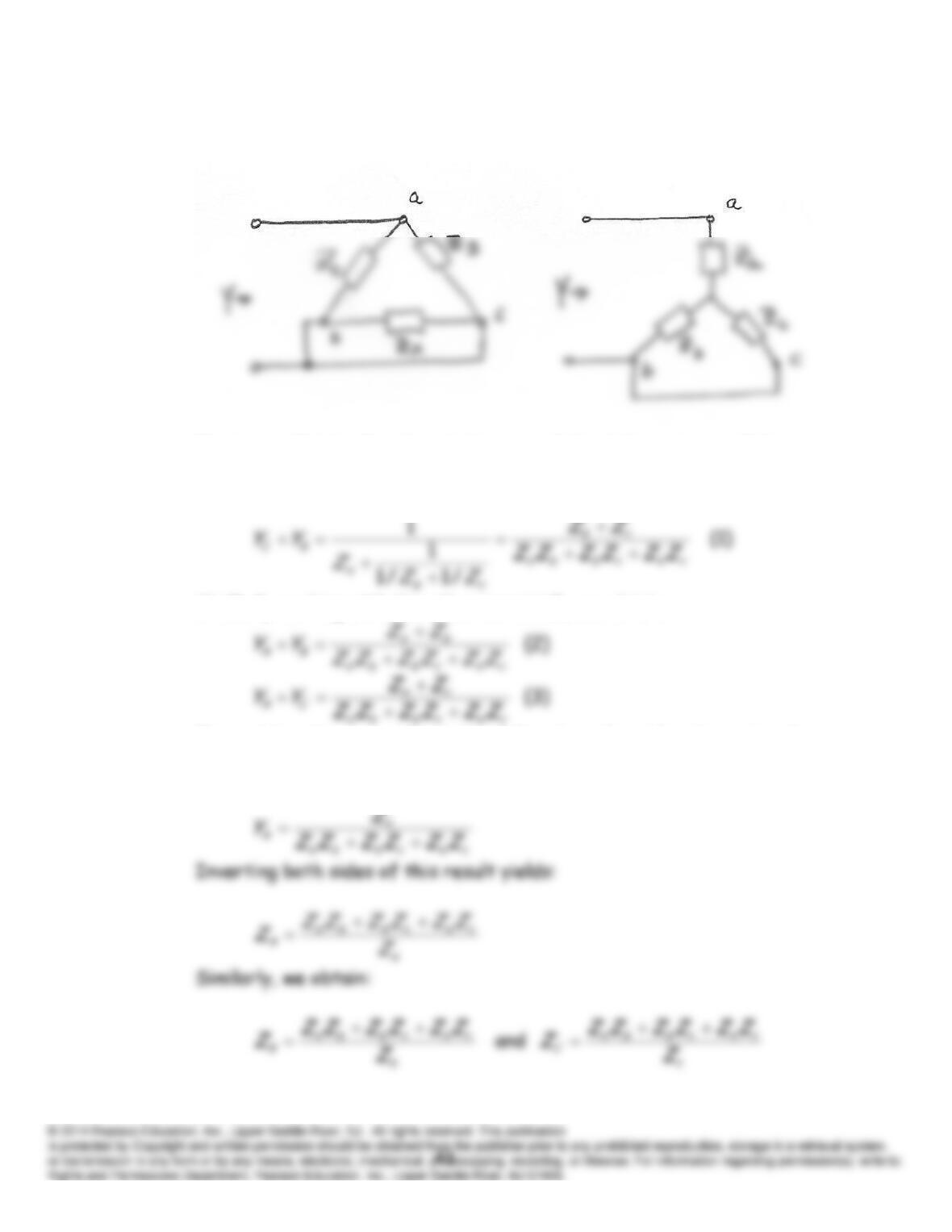
P5.99 As suggested in the hint given in the book, the impedances of the circuits
between terminals
a
and
b
with
c
open must be identical.
Equating the impedances, we obtain:
Then adding the respective sides of Equations 1 and 2, subtracting the
corresponding sides of Equation 3, and dividing both sides of the result
by 2, we have:
P5.100 As suggested in the hint, consider the circuits shown below. The
admittances of the circuits between terminals must be identical.
First, we will solve for the admittances of the delta in terms of the
impedances of the wye. Then we will invert the results to obtain
relationships between the impedances.
Similarly working with the other terminials, we obtain
Then adding the respective sides of Equations 2 and 3, subtracting the
corresponding sides of Equation 1, and dividing both sides of the result
by 2, we have:
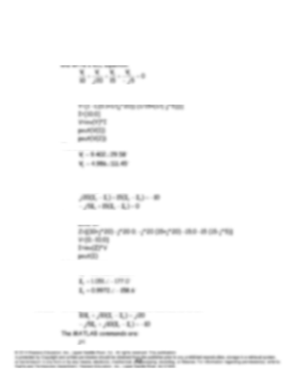
P5.101* First we write the KVL equation:
010
21 VV
Then, we enclose nodes 1 and 2 in a closed surface to form a supernode
The MATLAB commands are:
echo on
The answers are:
P5.102 Writing KVL equations around the meshes, we obtain
0)(2010 211 III
j
The MATLAB commands are:
Solving, we obtain:
4.1509402.0
P5.103* Writing KVL equations around the meshes, we obtain
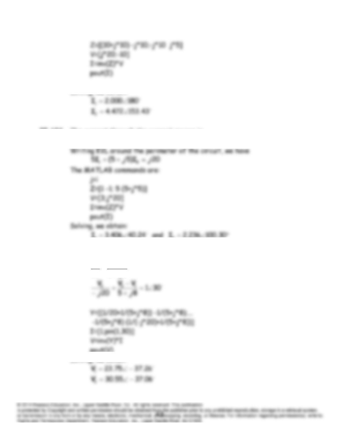
Solving, we obtain:
P5.104 The current through the current source is
3
21 II
P5.105 Writing KCL equations at nodes 1 and 2 we obtain
01
8520
211
j
VVV
pout(V)
Solving, we obtain
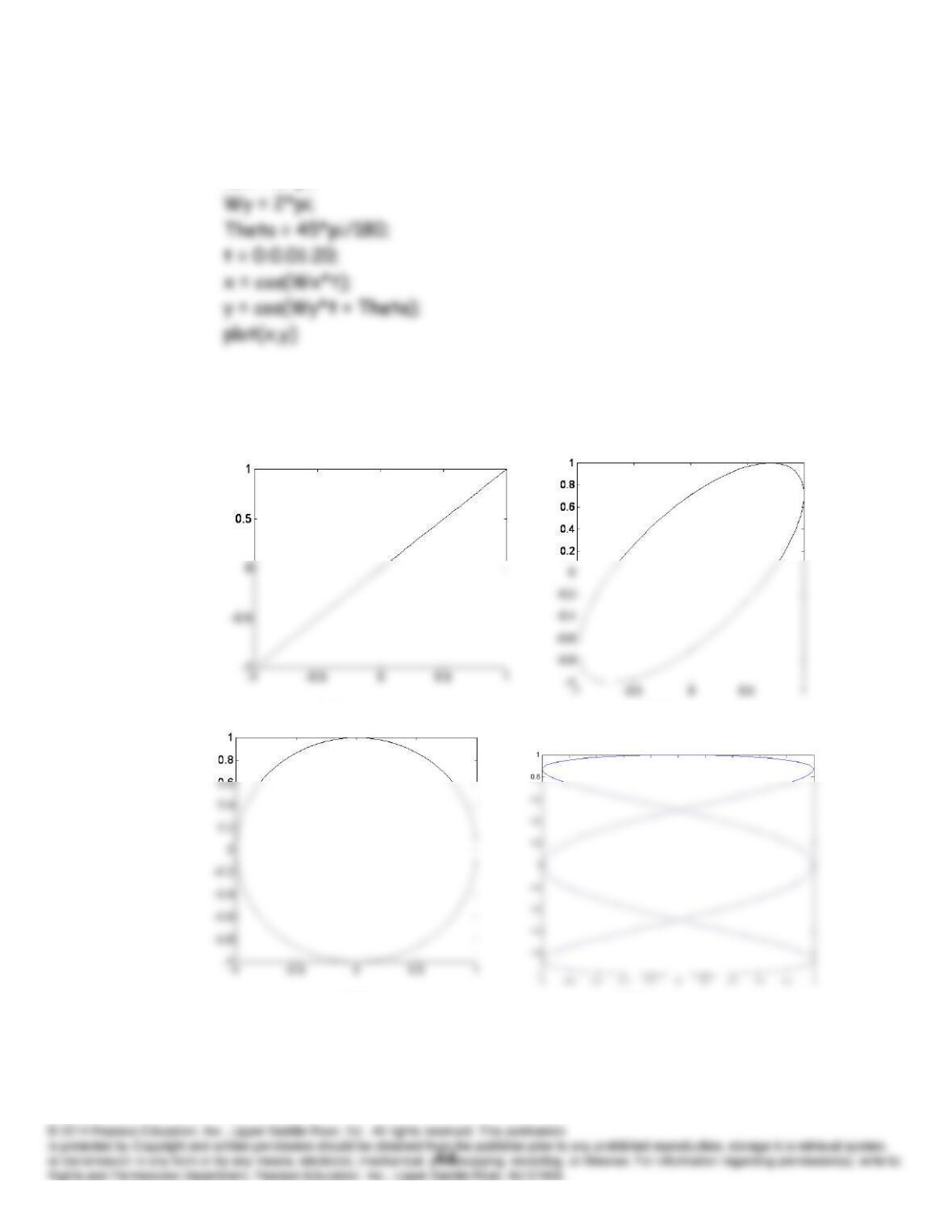
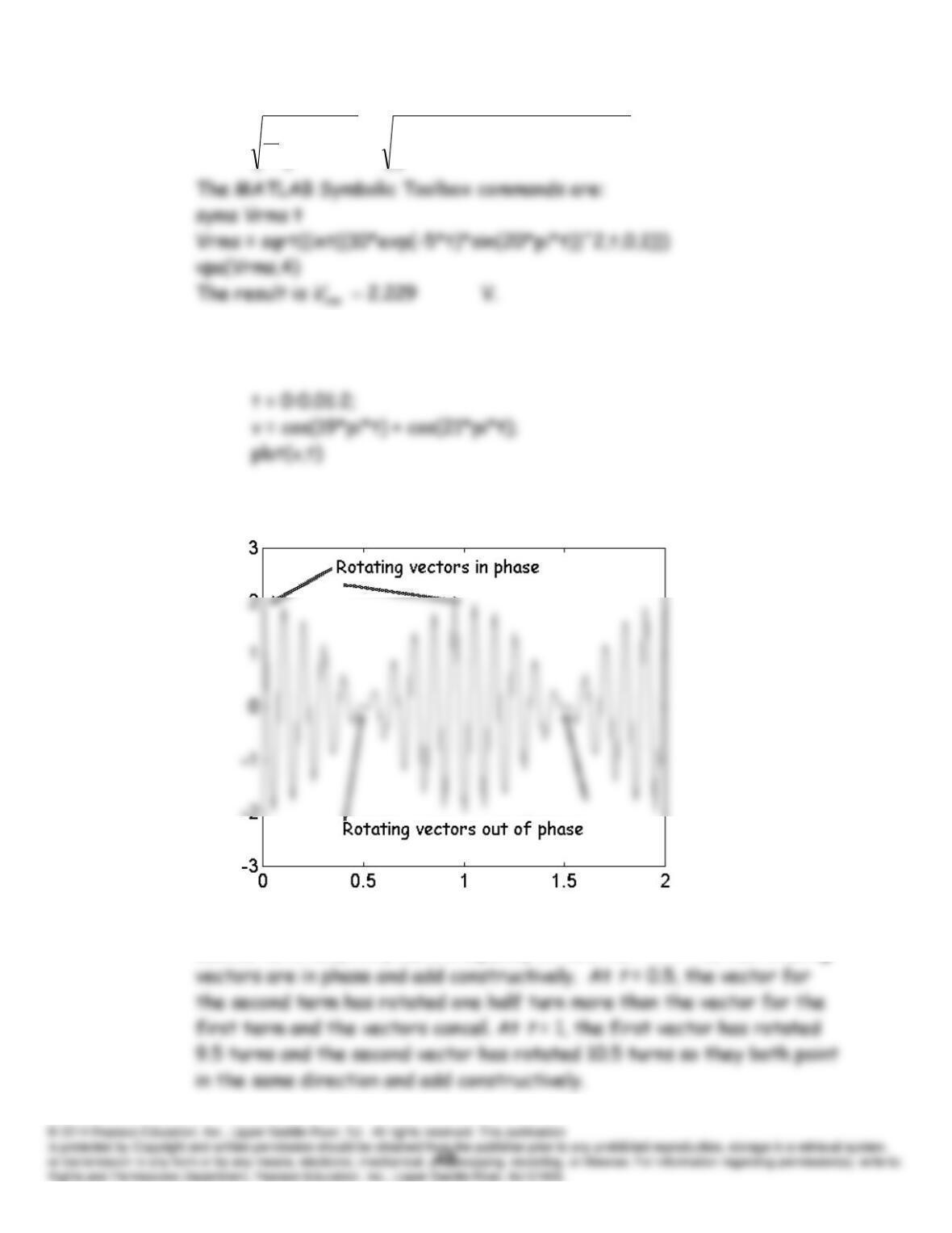
P5.106 A sequence of MATLAB instructions to accomplish the desired plot for
part (b) is
Wx = 2*pi;
By changing the parameters, we can obtain the plots for parts a, c, and d.
The resulting plots are
(a) (b)
(c) (d)
P5.107
1
2
2)20sin()5exp(10
1
dtttdttv
T
V
T
rms
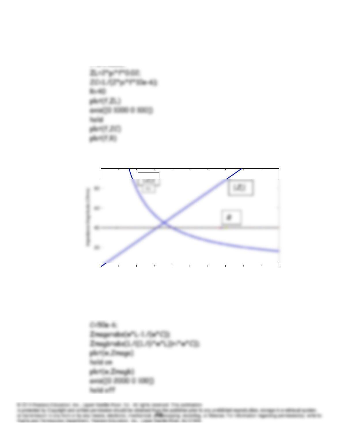
P5.108 A sequence of MATLAB commands to generate the desired plot is:
The resulting plot is
Notice that the first term cos(19
t
) has a frequency of 9.5 Hz while the
second term cos(21
t
) has a frequency of 10.5 Hz. At
t
= 0, the rotating
P5.109 A Matlab m-file that produces the desired plots is:
f=0:1:1000;
The resulting plot is:
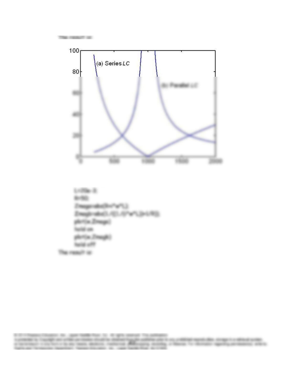
P5.110 A Matlab program that produces the desired plots is:
w=0:1:2000;
L=20e-3;
0 100 200 300 400 500 600 700 800 900 1000
0
100
frequency (Hz)
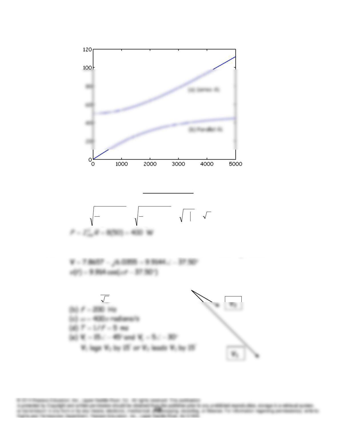
P5.111 A Matlab program that produces the desired plots is:
w=0:1:5000;
Practice Test
T5.1
A 828.28)3(
3
11 2
0
3
2
0
2
0
2
tdttdtti
T
I
T
rms
T5.2
5000.23301.45355.35355.3305455
jj
V
T5.3 (a)
V 61.10
15
1
rms
V
T5.4
A 457071.0
4514.14
010
51510
010
/
jjCjLjR
s
V
I
T5.5
35354213405500)1025)(30440(* 2
1
2
1
j
VIS
VA
T5.6 We convert the delta to a wye and connect the neutral points with an
ideal conductor.
3/823/
jZZY
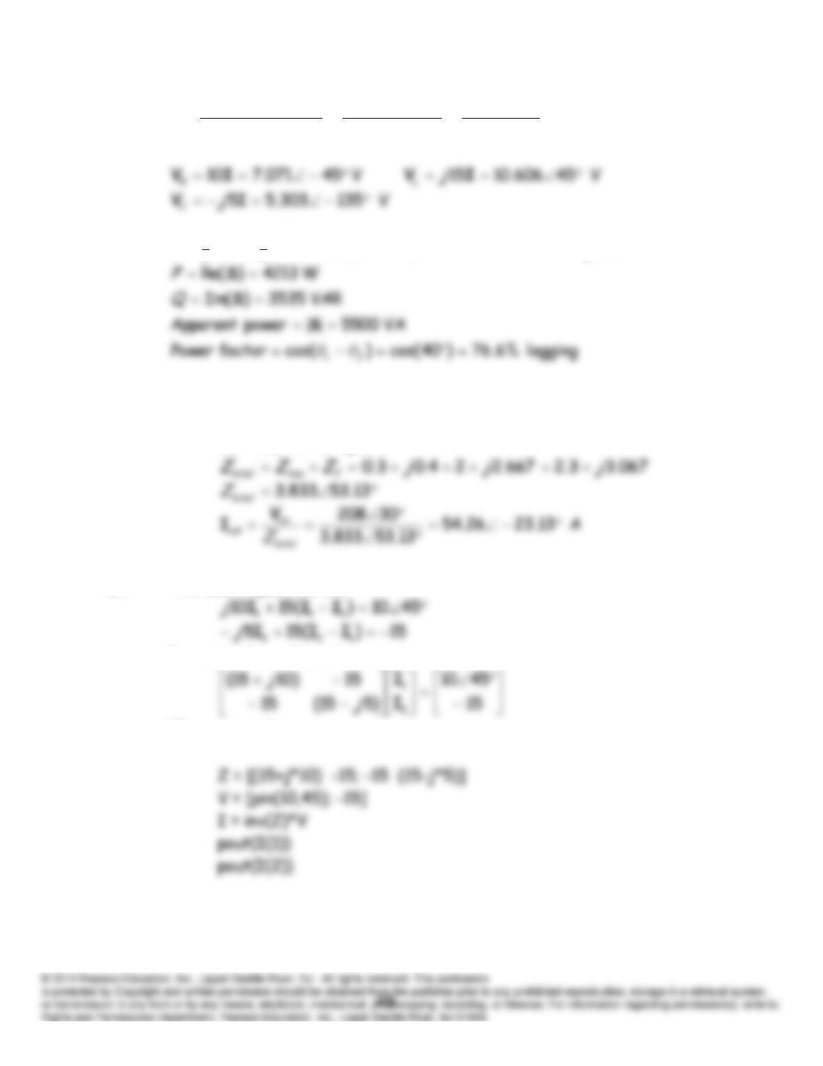
T5.7 The mesh equations are:
In matrix form these become
The commands are: