The Operational Amplifier
Assessment Problems
AP 5.1 [a] Derive the expression for the output voltage using circuit analysis:
vo=(−Rf/Ri)vs=(−80/16)vs,so vo=−5vs;
[b] Use the negative power supply value to determine the largest input
voltage:
AP 5.2 From Assessment Problem 5.1
Use the negative power supply value to determine one limit on the value of Rx:
5–1
5
5–2 CHAPTER 5. The Operational Amplifier
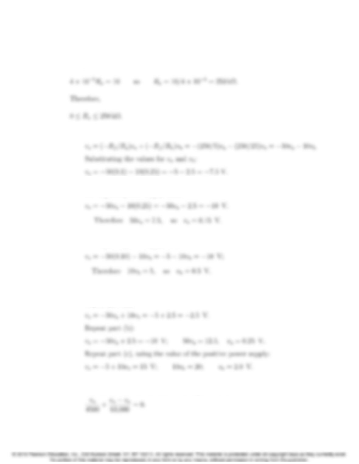
Since we cannot have negative resistor values, the lower limit for Rxis 0. Now
use the positive power supply value to determine the upper limit on the value
of Rx:
AP 5.3 [a] This is an inverting summing amplifier so
[b] Substitute the value for vbinto the equation for vofrom part (a) and use
the negative power supply value:
[c] Substitute the value for vainto the equation for vofrom part (a) and use
the negative power supply value:
[d] The effect of reversing polarity is to change the sign on the vbterm in
each equation from negative to positive.
Repeat part (a):
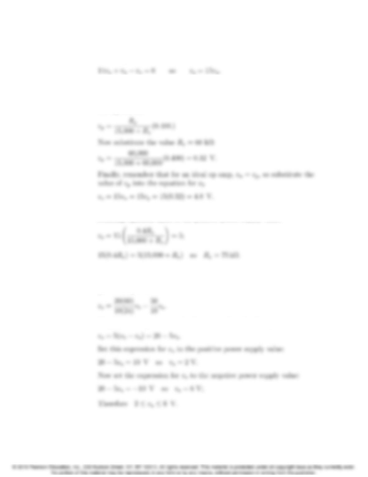
AP 5.4 [a] Write a node voltage equation at vn; remember that for an ideal op amp,
the current into the op amp at the inputs is zero:
Problems 5–3
Solve for voin terms of vnby multiplying both sides by 63,000 and
collecting terms:
Now use voltage division to calculate vp. We can use voltage division
because the op amp is ideal, so no current flows into the non-inverting
input terminal and the 400 mV divides between the 15 kΩresistor and
the Rxresistor:
[b] Substitute the expression for vpinto the equation for voand set the
resulting equation equal to the positive power supply value:
AP 5.5 [a] Since this is a difference amplifier, we can use the expression for the
output voltage in terms of the input voltages and the resistor values
given in Eq. 5.22:
Simplify this expression and subsitute in the value for vb:
5–4 CHAPTER 5. The Operational Amplifier
[b] Begin as before by substituting the appropriate values into Eq. 5.8:
AP 5.6 Ra=Rc=1.5Ω;Rb= 12 Ω.
Then,
Acm =1.5Rd−1.5(12)
1.5(1.5+Rd
;
Therefore,
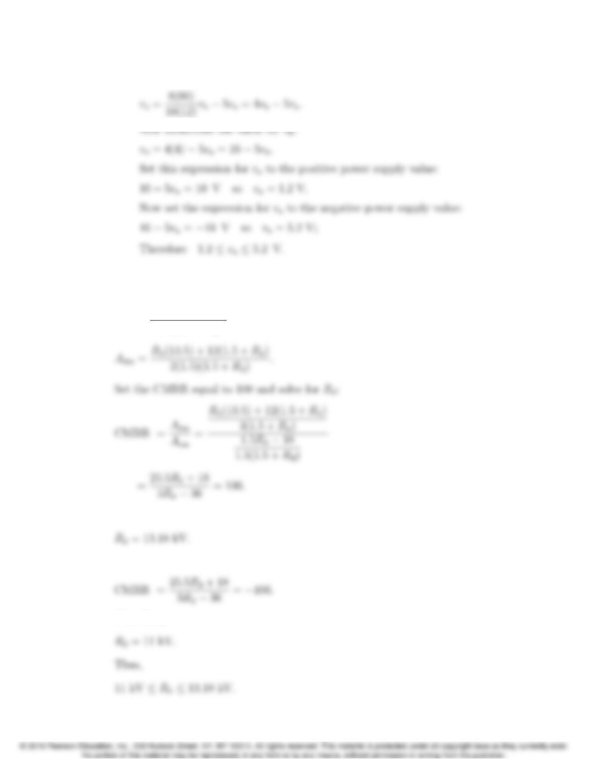
Set the CMRR equal to −100 and solve for Rd:
Therefore,
Problems 5–5
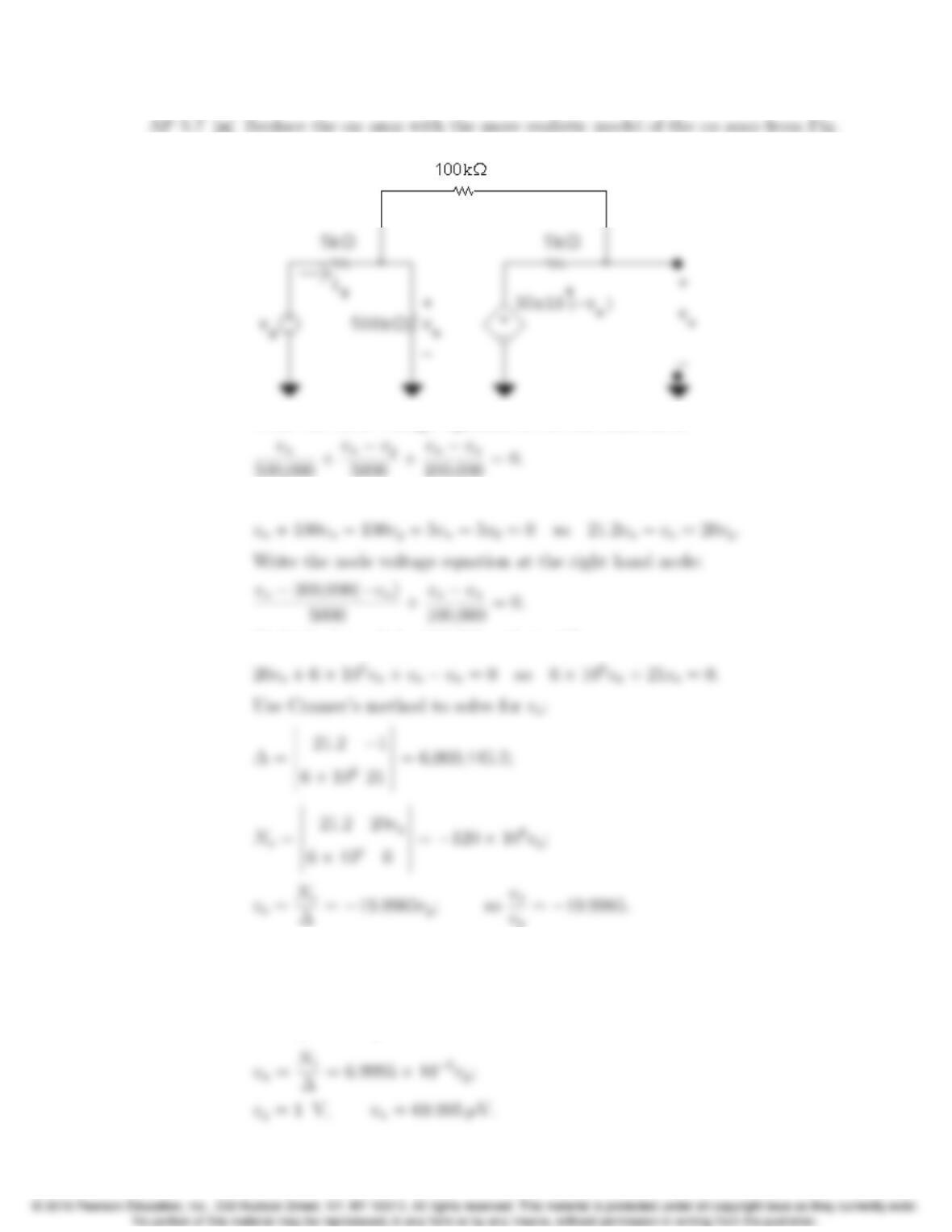
5.18:
Write the node voltage equation at the left hand node:
Multiply both sides by 500,000 and simplify:
Multiply through by 100,000 and simplify:
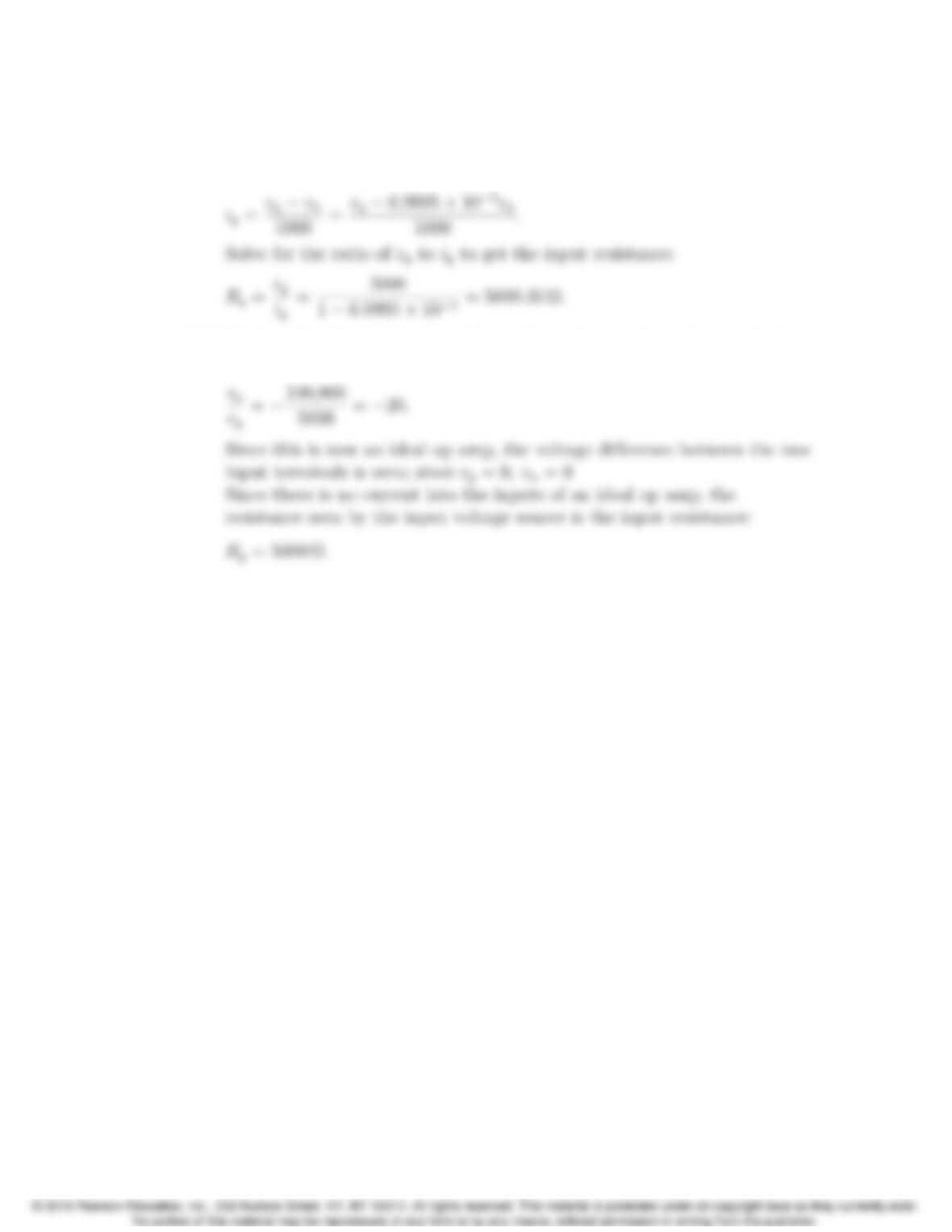
[b] Use Cramer’s method again to solve for vn:
N1=
20vg−1
021
= 420vg;
5–6 CHAPTER 5. The Operational Amplifier
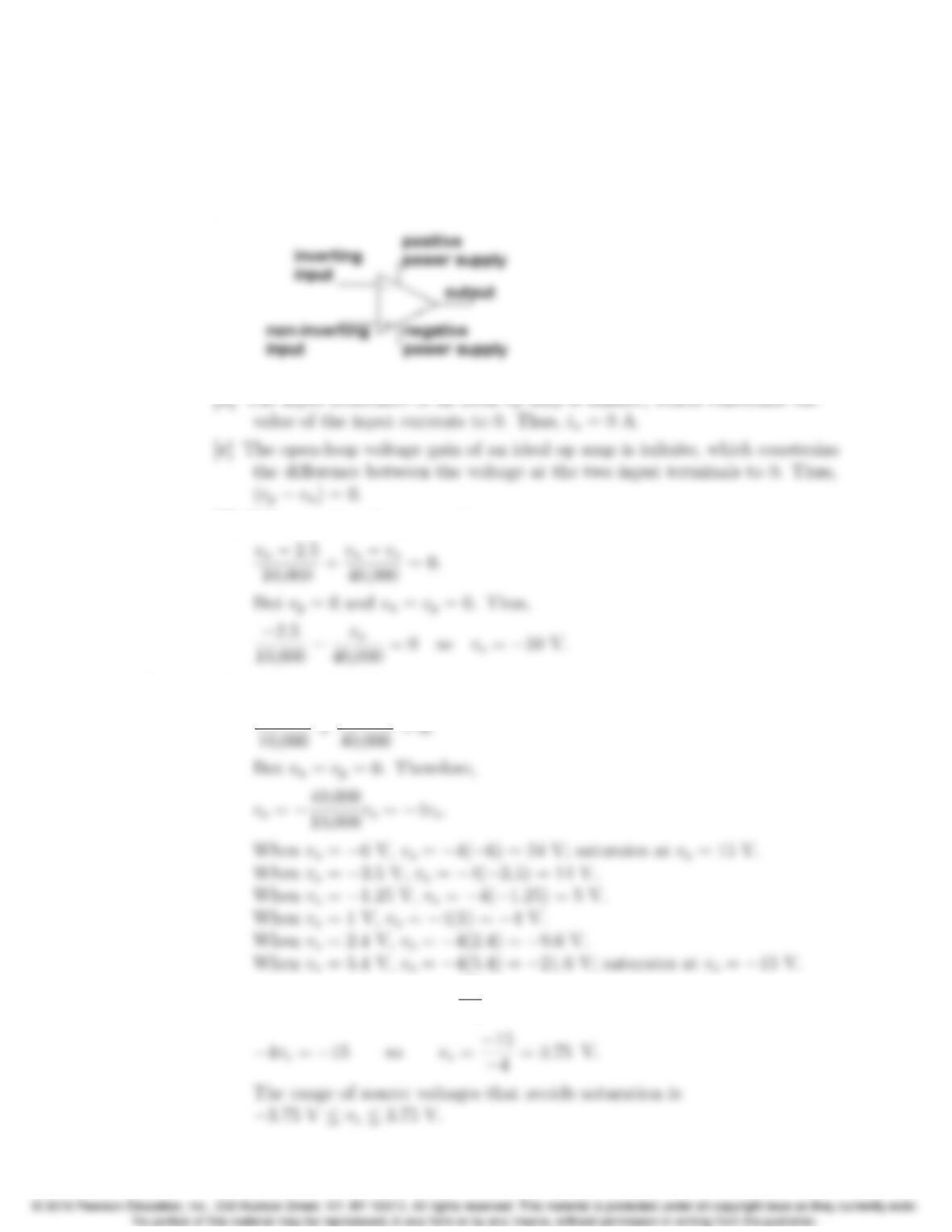
[c] The resistance seen at the input to the op amp is the ratio of the input
voltage to the input current, so calculate the input current as a function
of the input voltage:
[d] This is a simple inverting amplifier configuration, so the voltage gain is
the ratio of the feedback resistance to the input resistance:
Problems 5–7
Problems
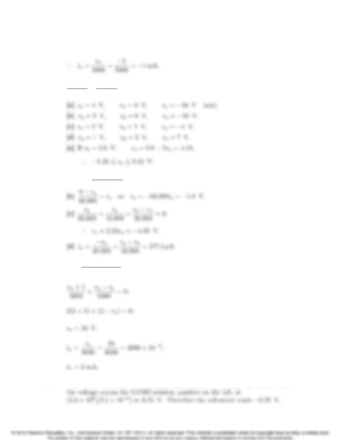
P 5.1 [a] The five terminals of the op amp are identified as follows:
[d] Write a node voltage equation at vn:
P 5.2 [a] Let the value of the voltage source be vs:
vn−vs
[b] −4vs= 15 so vs=15
−4=−3.75 V;
5–8 CHAPTER 5. The Operational Amplifier
P 5.3 vo=−(0.5×10⁻³)(10,000) = −5 V;
P 5.4 vb−va
20 +vb−vo
100 =0,therefore vo=6vb−5va.
P 5.5 [a] ia=240 ×10−3
8000 = 30 µA.
P 5.6 vp=5000
5000 + 10,000(6) = 2 V = vn;
P 5.7 Since the current into the inverting input terminal of an ideal op-amp is zero,
Problems 5–9
P 5.8 [a] The gain of an inverting amplifier is the negative of the ratio of the
feedback resistor to the input resistor. If the gain of the inverting
amplifier is to be 2.5, the feedback resistor must be 2.5 times as large as
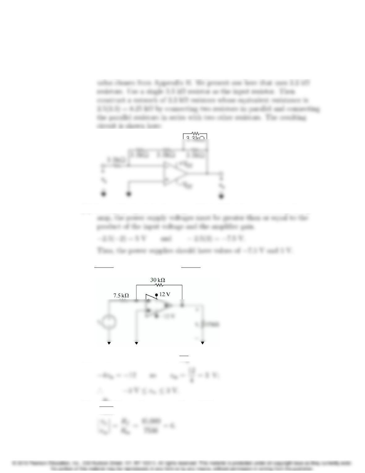
the input resistor. There are many possible designs that use a resistor
[b] To amplify signals in the range −2 V to 3 V without saturating the op
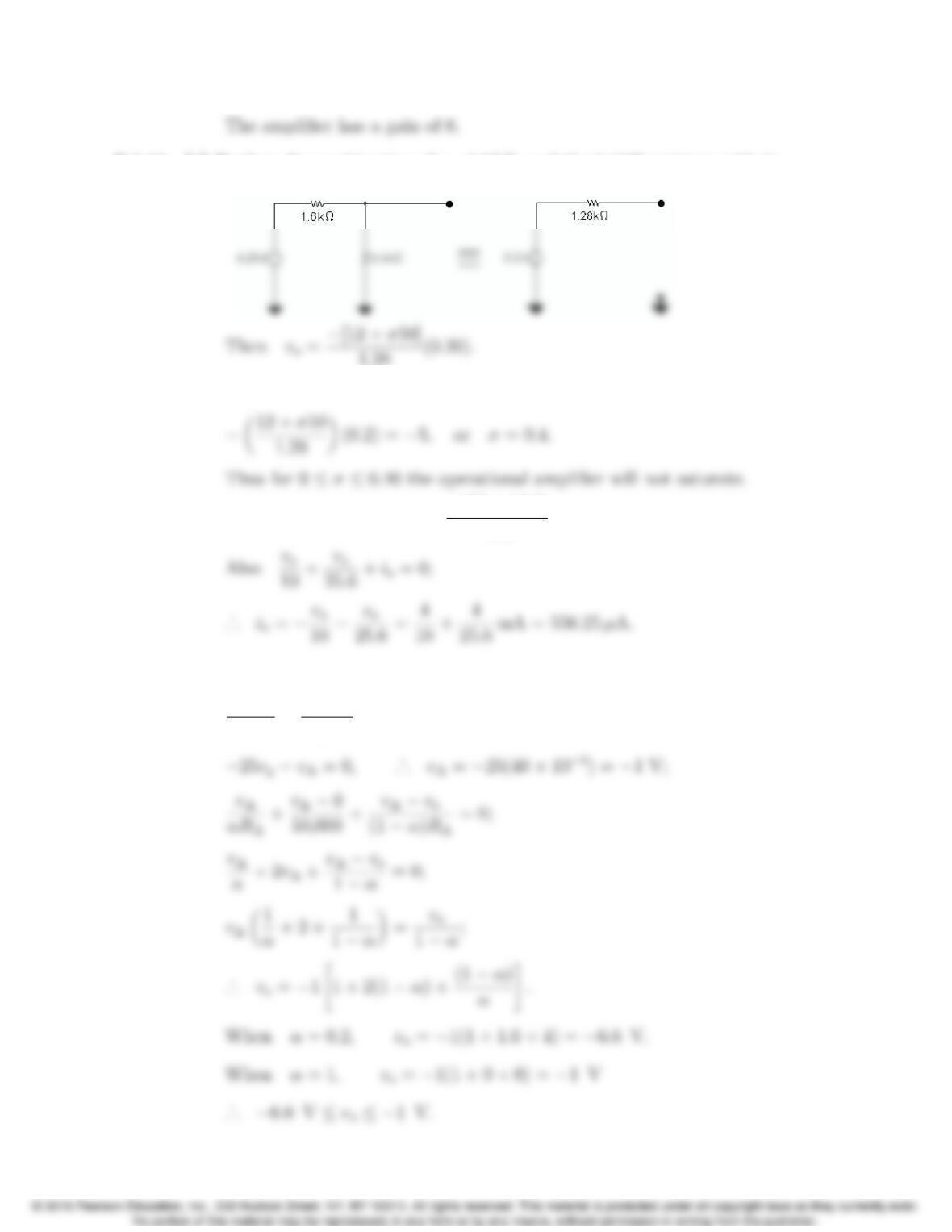
P 5.9 [a] 30,000
Rin
= 4 so Rin =30,000
4= 7500 = 7.5 kΩ,
[b] −4vin = 12 so vin =12
[c] −Rf
7500(2) = −12 so Rf= 45 kΩ;
5–10 CHAPTER 5. The Operational Amplifier
P 5.10 [a] Replace the combination of vg,1.6 kΩ, and the 6.4 kΩresistors with its
Th´evenin equivalent.
1.28 (0.20).
At saturation vo=−5 V; therefore
[b] When σ=0.272,v
o=−(12 + 13.6)
1.28 (0.20) = −4V.
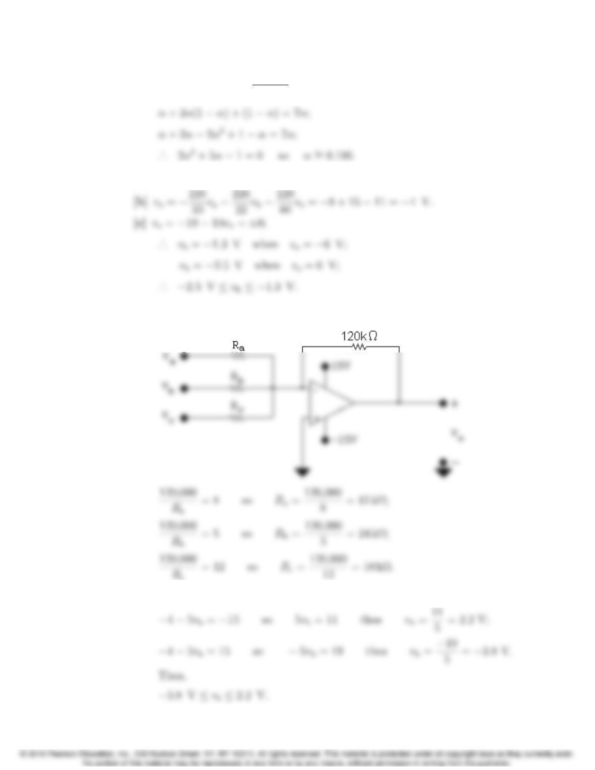
P 5.11 [a] Let v∆be the voltage from the potentiometer contact to ground. Then
0−vg
2000 +0−v∆
50,000 = 0;
Problems 5–11
[b] −1“1 + 2(1 −α)+(1 −α)
α#=−7;
P 5.12 [a] This circuit is an example of an inverting summing amplifier.
P 5.13 [a]
[b] −[8(2) + 5vb+ 12(−1)] = −4−5vb;
5–12 CHAPTER 5. The Operational Amplifier
P 5.14 vo=−“Rf
3000(0.15) + Rf
5000(0.1) + Rf
25,000(0.25)#;
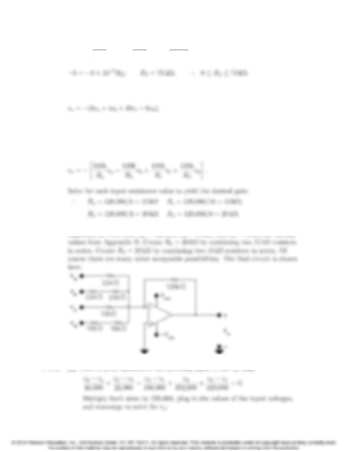
P 5.15 We want the following expression for the output voltage:
This is an inverting summing amplifier, so each input voltage is amplified by a
gain that is the ratio of the feedback resistance to the resistance in the
forward path for the input voltage. Pick a feedback resistor with divisors of 8,
4, 10, and 6 – say 120 kΩ:
Now create the 5 resistor values needed from the realistic resistor values in
Problems 5–13
[b] Write a KCL equation at the inverting input to the op amp. Use the given
values of input voltages in the equation:
44 −5.5va−10 −11 + 5 + 8 −vo= 0 so vo= 36 −5.5va.
Set voto the positive power supply voltage and solve for va:
P 5.17 [a] 8−4
40,000 +8−9
22,000 +8−13
100,000 +8
352,000 +8−v0
Rf
= 0;
P 5.18 [a] This circuit is an example of the non-inverting amplifier.
[b] Use voltage division to calculate vp:
5–14 CHAPTER 5. The Operational Amplifier
[c] 1.8vs= 12 so vs=6.67 V;
P 5.19 [a] The circuit shown is a non-inverting amplifier.
P 5.20 [a] vp=vn=45
75vg=0.6vg;
[b] vo=2.52vg=±10.
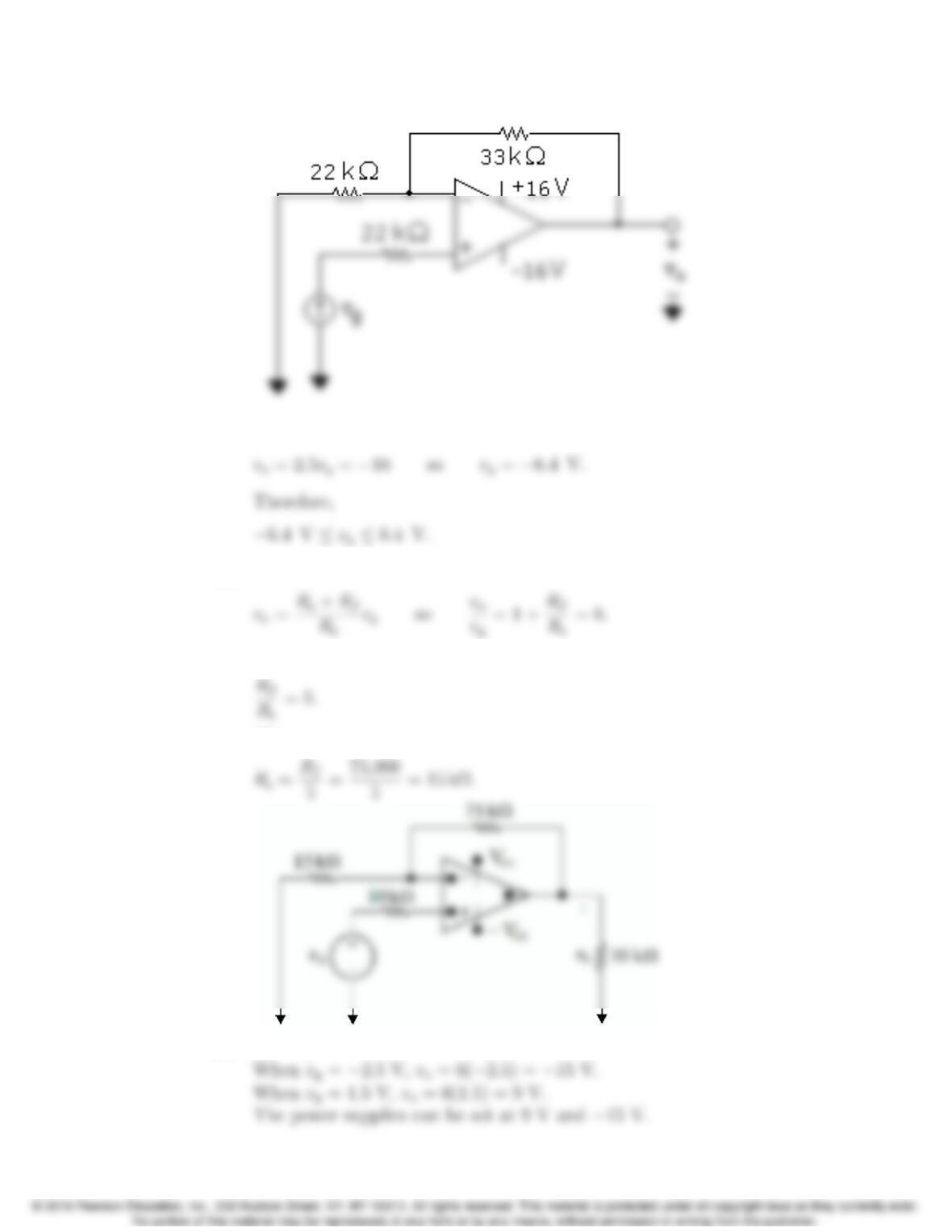
P 5.21 [a] From the equation for the non-inverting amplifier,
Rs+Rf
Problems 5–15
[b] vo=2.5vg= 16 so vg=6.4V.
P 5.22 [a] From Eq. 5.7,
So,
Thus,
[b] vo=6vg.
5–16 CHAPTER 5. The Operational Amplifier
P 5.23 [a] This circuit is an example of a non-inverting summing amplifier.
[b] Write a KCL equation at vpand solve for vpin terms of vs:
vp−vs
15,000 +vp−6
30,000 = 0;
P 5.24 [a] vp−va
Ra
+vp−vb
Rb
+vp−vc
Rc
= 0;
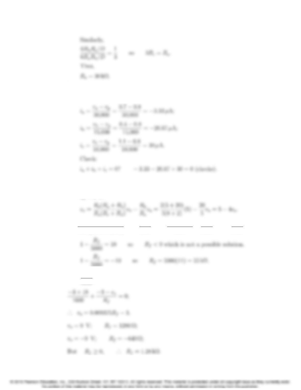
where D=RbRc+RaRc+RaRb.
By hypothesis,
Problems 5–17
[b] vo= 1(0.7) + 2(0.4) + 3(1.1) = 4.8V
vn=vo/6=0.8V=vp;
P 5.25 [a] This is a difference amplifier circuit.
[b] Use Eq. 5.8 with Ra=5kΩ,Rb= 20 kΩ,Rc=8kΩ,Rd= 2 kΩ, and
vb= 5 V:
[c] 2000(5000 + Rf)
5000(8000 + 2000)(5) −Rf
5000(2) = 5000 + Rf
5000 −2Rf
5000 =1−Rf
5000;
5000 =−10 so Rf= 5000(11) = 55 kΩ.
P 5.26 vp=1500
9000(−18) = −3V=vn;
5–18 CHAPTER 5. The Operational Amplifier
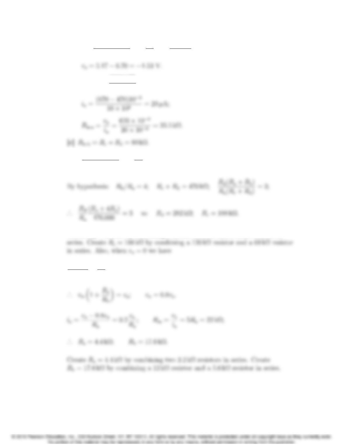
P 5.27 [a] vo=Rd(Ra+Rb)
Ra(Rc+Rd)vb−Rb
Ra
va=47(110)
10(80) (0.80) −10(0.67);
[b] vn=vp=(800)(47)
80 = 470 mV;
P 5.28 vo=Rd(Ra+Rb)
Ra(Rc+Rd)vb−Rb
Ra
va.
Create Rd= 282 kΩby combining a 270 kΩresistor and a 12 kΩresistor in
vn−va
Ra
+vn
Rb
= 0;