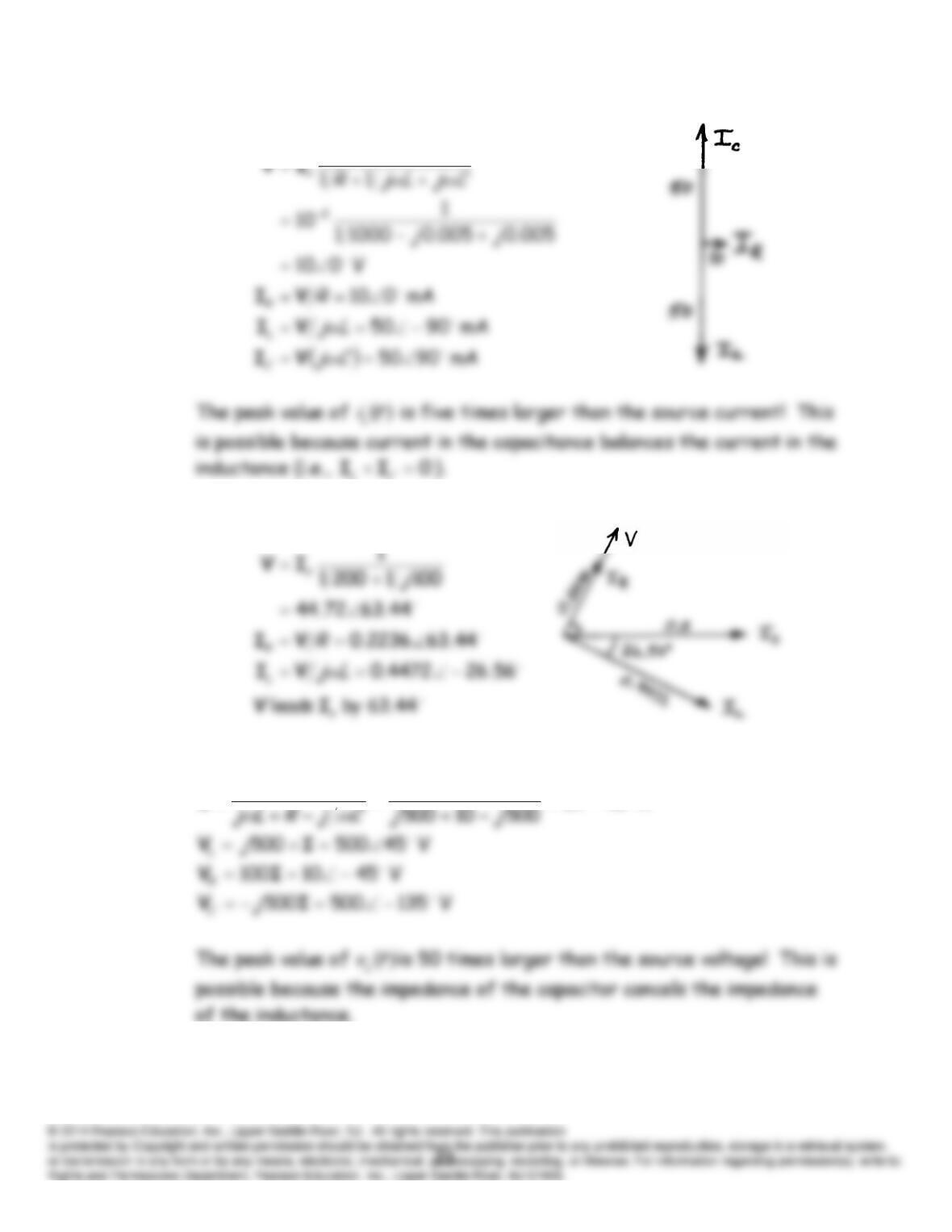
P5.45*
5.46
P5.47
V 4510
s
V
A 451
4510
s
V
I
1
mA 010
s
I
05.0
s
I
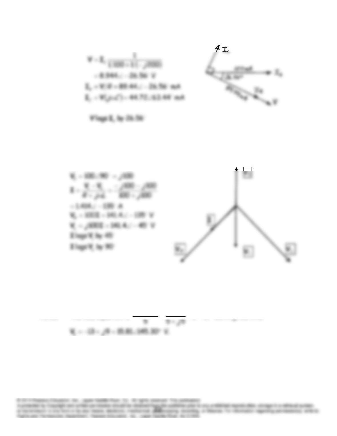
P5.48*
P5.49
10090100
1
j
V
P5.50 The KCL equation is
.03
20 1
1
j
V
V
Solving, we find
mA 0100
s
I
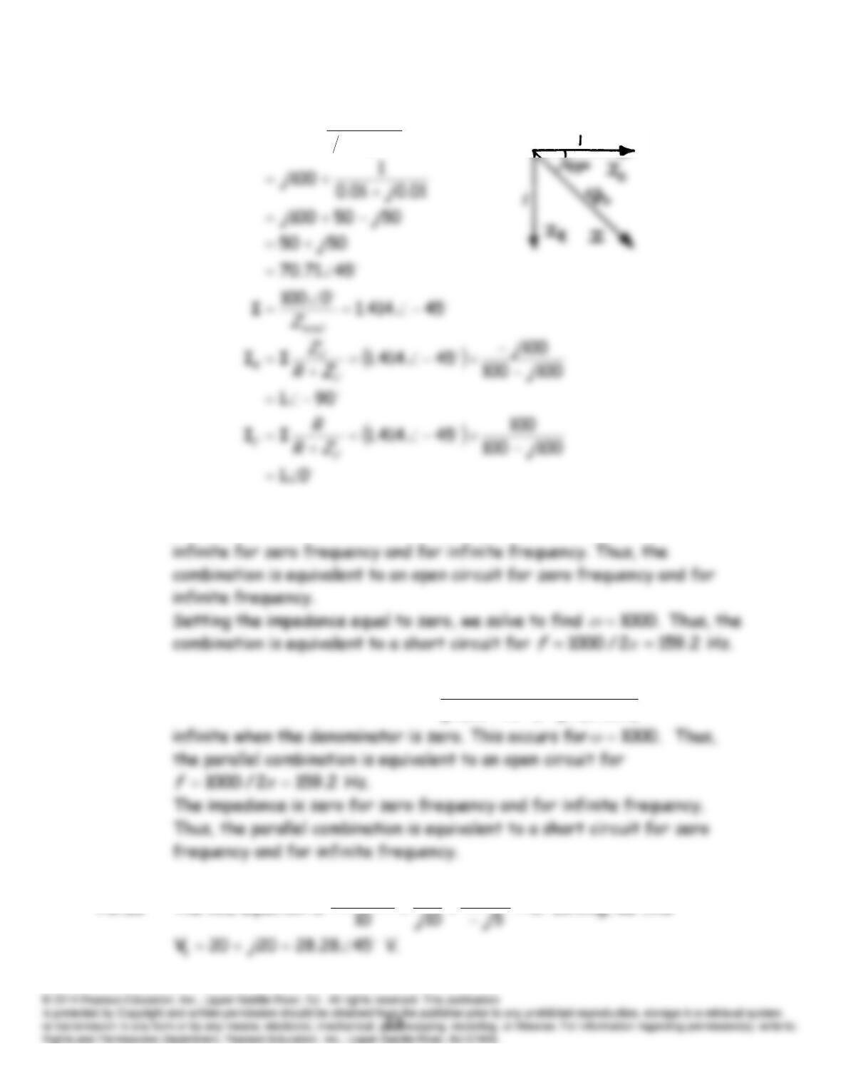
P5.51
P5.52 (a) The impedance is given by
)1050/()02.0( 6
jjZ
which is
(b) The impedance is given by
)02.0/()1050(
1
6
jj
Z
which is
P5.53 The KCL equation is
.0
10
20 11
1
j
VV
V
Solving, we find
1
1
CjR
LjZ
total
ω
ω
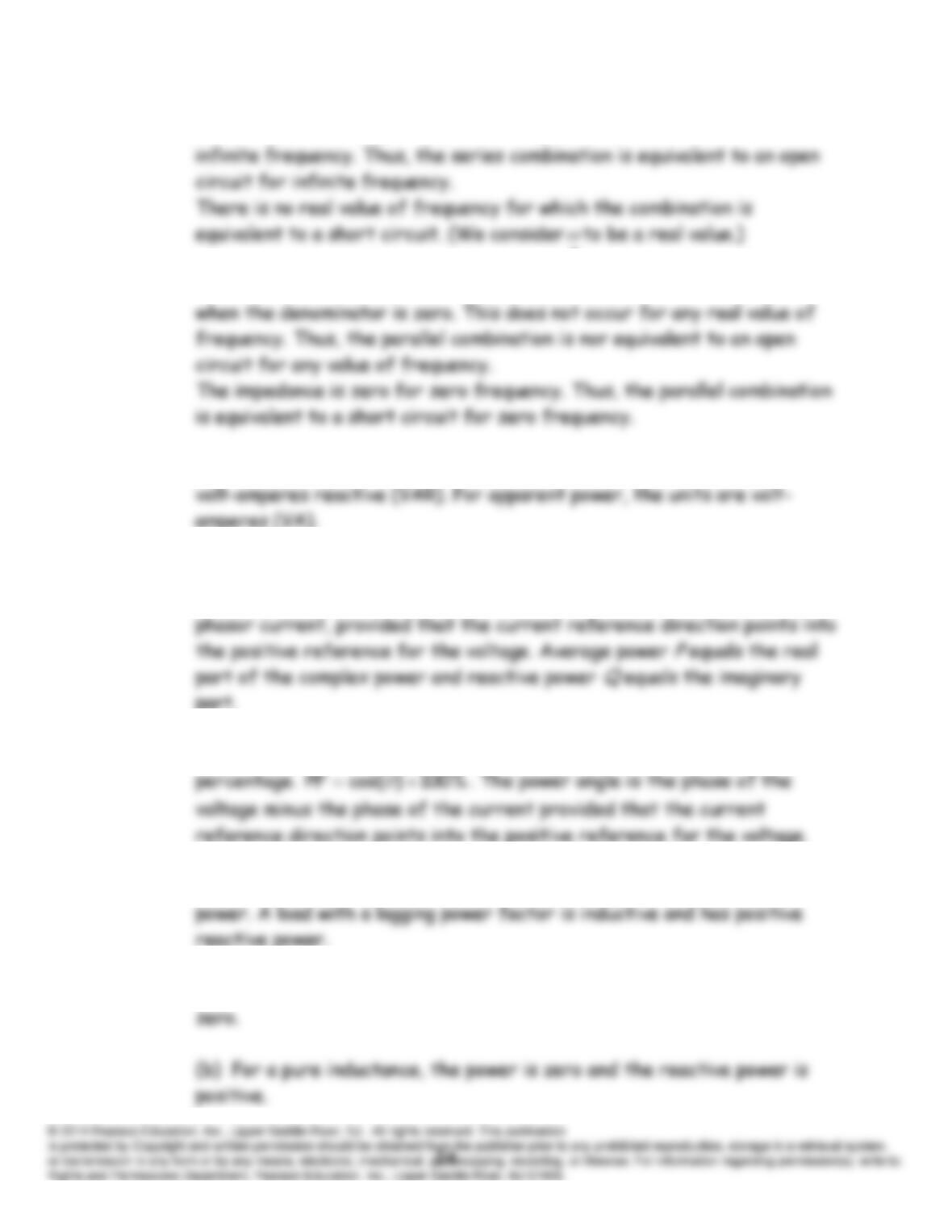
P5.54 (a) The impedance is given by
)02.0(50
jZ
which is infinite for
(b) The impedance is given by
)02.0/(02.0
1
j
Z
which is infinite
P5.55 The units for real power are watts (W). For reactive power, the units are
P5.56 Complex power delivered to a circuit element is equal to one half of the
phasor voltage across the element times the complex conjugate of the
P5.57 Power factor is the cosine of the power angle. It is often expressed as a
P5.58 A load with a leading power factor is capacitive and has negative reactive
P5.59 (a) For a pure resistance, the power is positive and the reactive power is
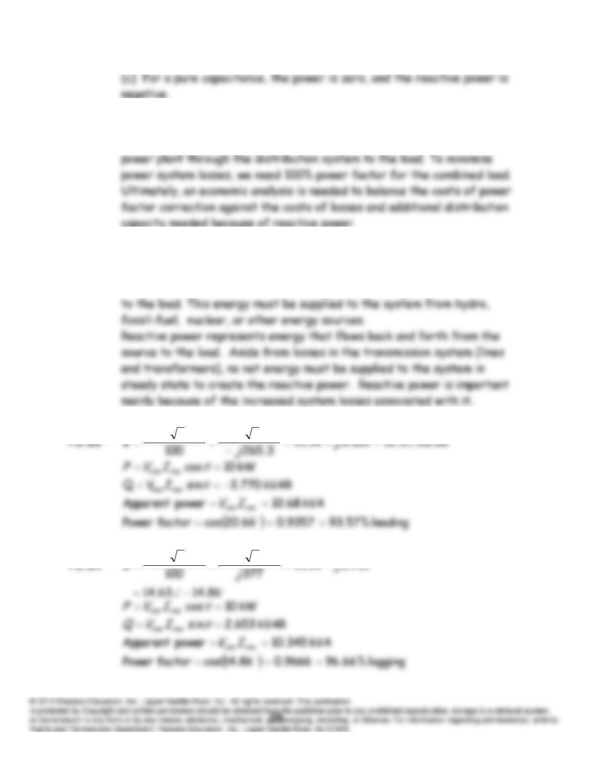
P5.60 Usually, power factor correction refers to adding capacitances in parallel
with an inductive load to reduce the reactive power flowing from the
P5.61 See Figure 5.23 in the book.
P5.62 Real power represents a net flow, over time, of energy from the source
021000
021000
021000
021000
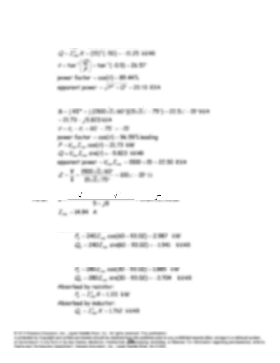
P5.65* This is a capacitive load because the reactance is negative.
kW 5.22100)15(22
RIP rms
P5.66 We have
302280602240
Delivered by Source
A
:
Absorbed by Source
B
:
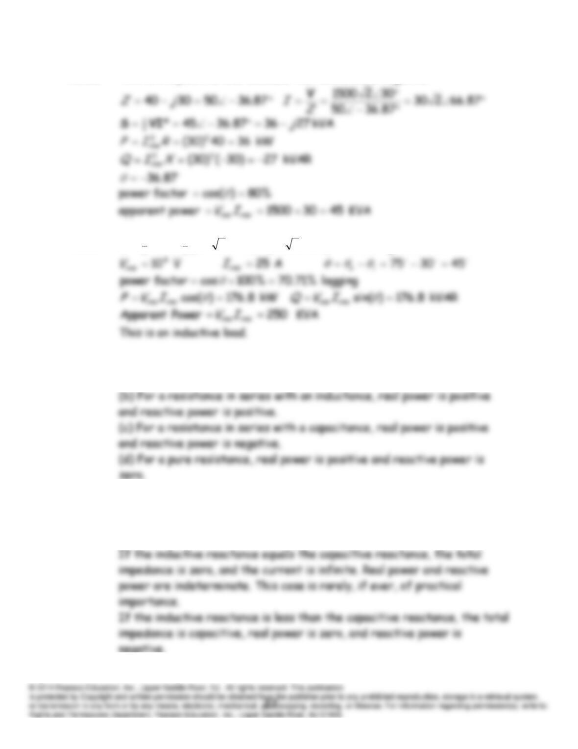
P5.68 This is a capacitive load because the reactance is negative.
P5.69
kVA 8.1768.176)*30225()75210(* 4
2
1
2
1
j
VIS
P5.70 (a) For a pure capacitance, real power is zero and reactive power is
negative.
P5.71 If the inductive reactance is greater than the capacitive reactance, the
total impedance is inductive, real power is zero, and reactive power is
positive.
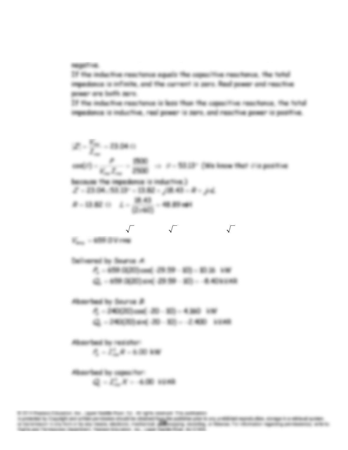
P5.72 If the inductive reactance is greater than the capacitive reactance, the
total impedance is capacitive, real power is zero, and reactive power is
P5.73 Apparent power
rmsrms IV
rms
I
2402500
A 10.417
rms
I
P5.74
59.2920.65920224010220)1515(
j
A
V
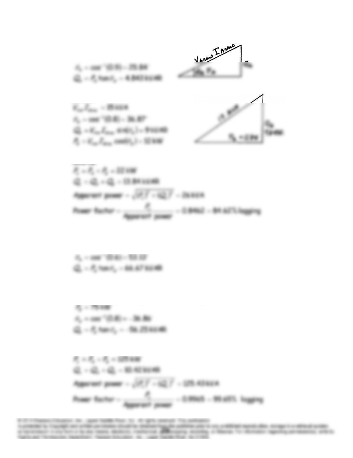
P5.75* Load A:
kW 10
A
P
Load
B
:
P5.76 Load A:
kW 50
A
P
Load
B
:
The phase angle is negative for a leading power factor.
Source:
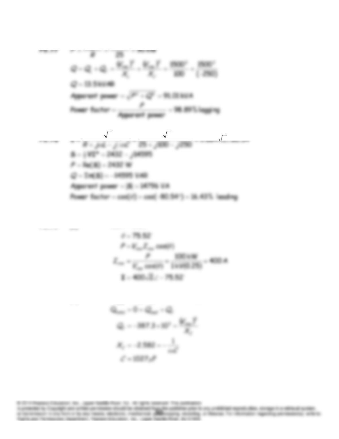
15002
2
V
021500021500
P5.79* (a)
(b)
The capacitor must be rated for at least 387.3 kVAR. With the
capacitor in place, we have:
25.0cos
θ
kVAR 3.387sin
θ
IVQ
rmsrms
load
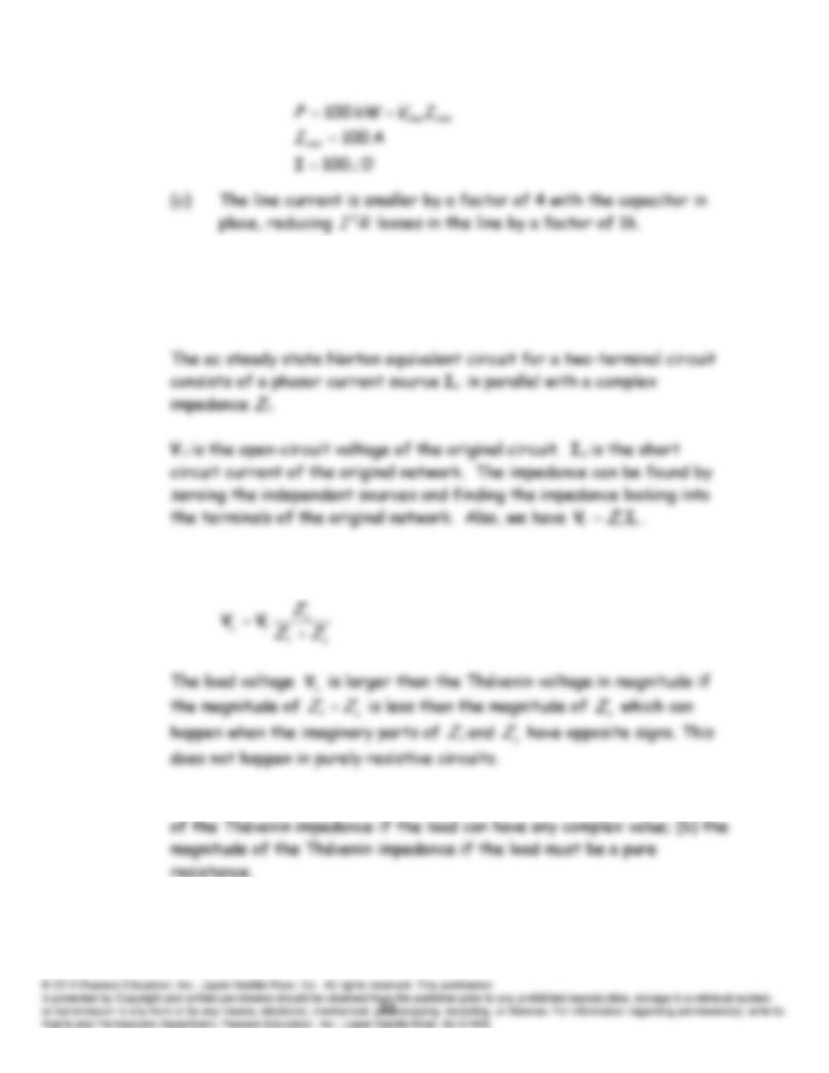
P5.80 The ac steady state Thévenin equivalent circuit for a two-terminal circuit
consists of a phasor voltage source V
t
in series with a complex impedance
Zt.
P5.81 The load voltage is given by the voltage divider principle.
P5.82 To attain maximum power, the load must equal (a) the complex conjugate
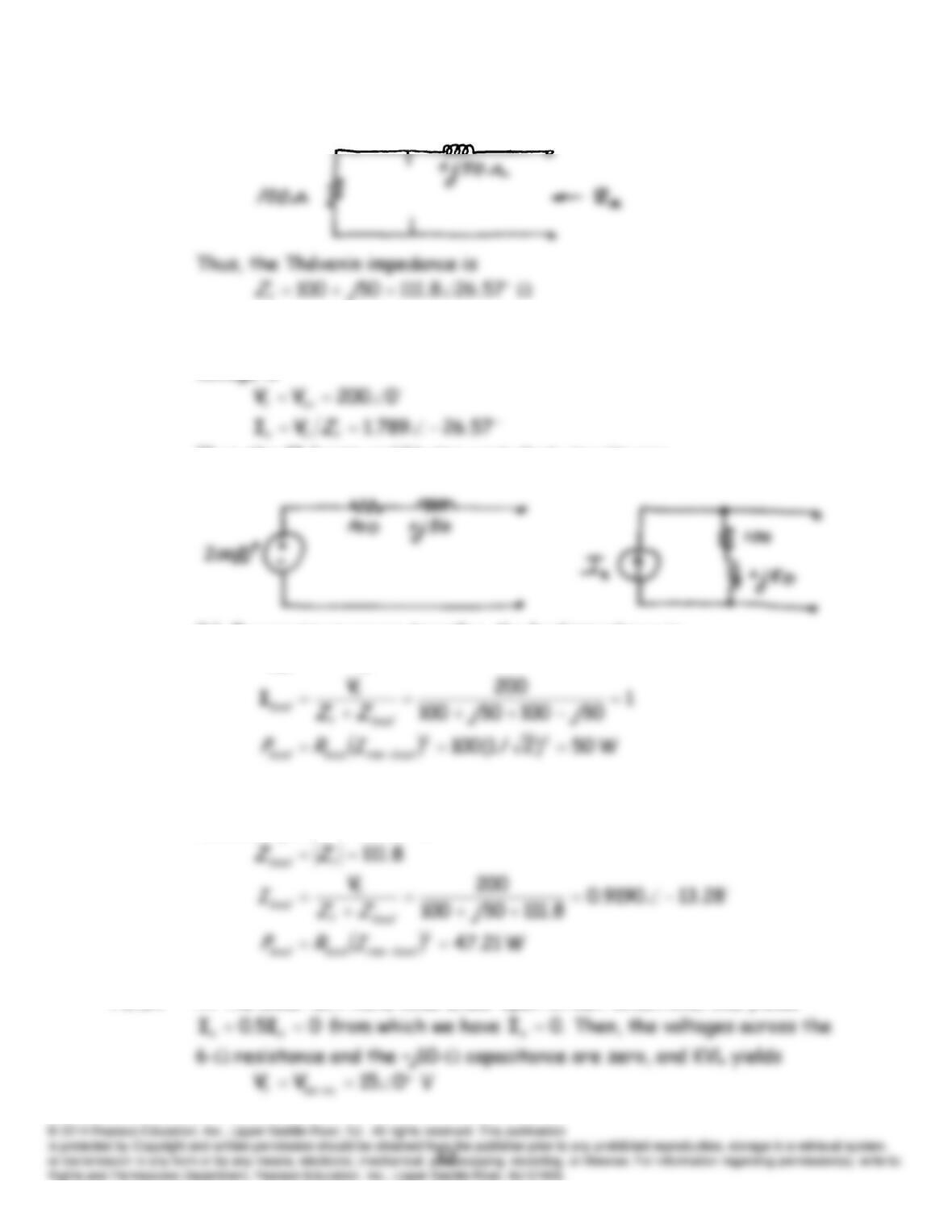
P5.83* (a) Zeroing the current source, we have:
Under open circuit conditions, there is zero voltage across the
inductance, the current flows through the resistance, and the Thévenin
voltage is
Thus, the Thévenin and Norton equivalent circuits are:
(b) For maximum power transfer, the load impedance is
50100
load
jZ
(c) In the case for which the load must be pure resistance, the load for
maximum power transfer is
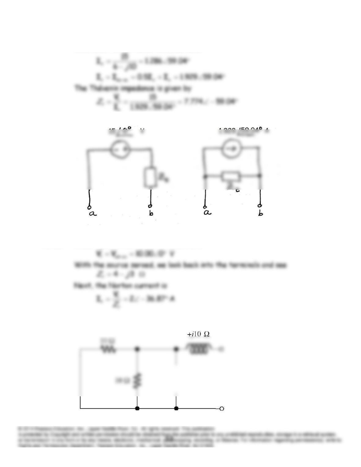
P5.84 At the lower left-hand node under open-circuit conditions, KCL yields
With short circuit conditions, we have
Finally, the equivalent circuits are:
P5.85 Under open-circuit conditions, we have
P5.86 Zeroing sources, we have:
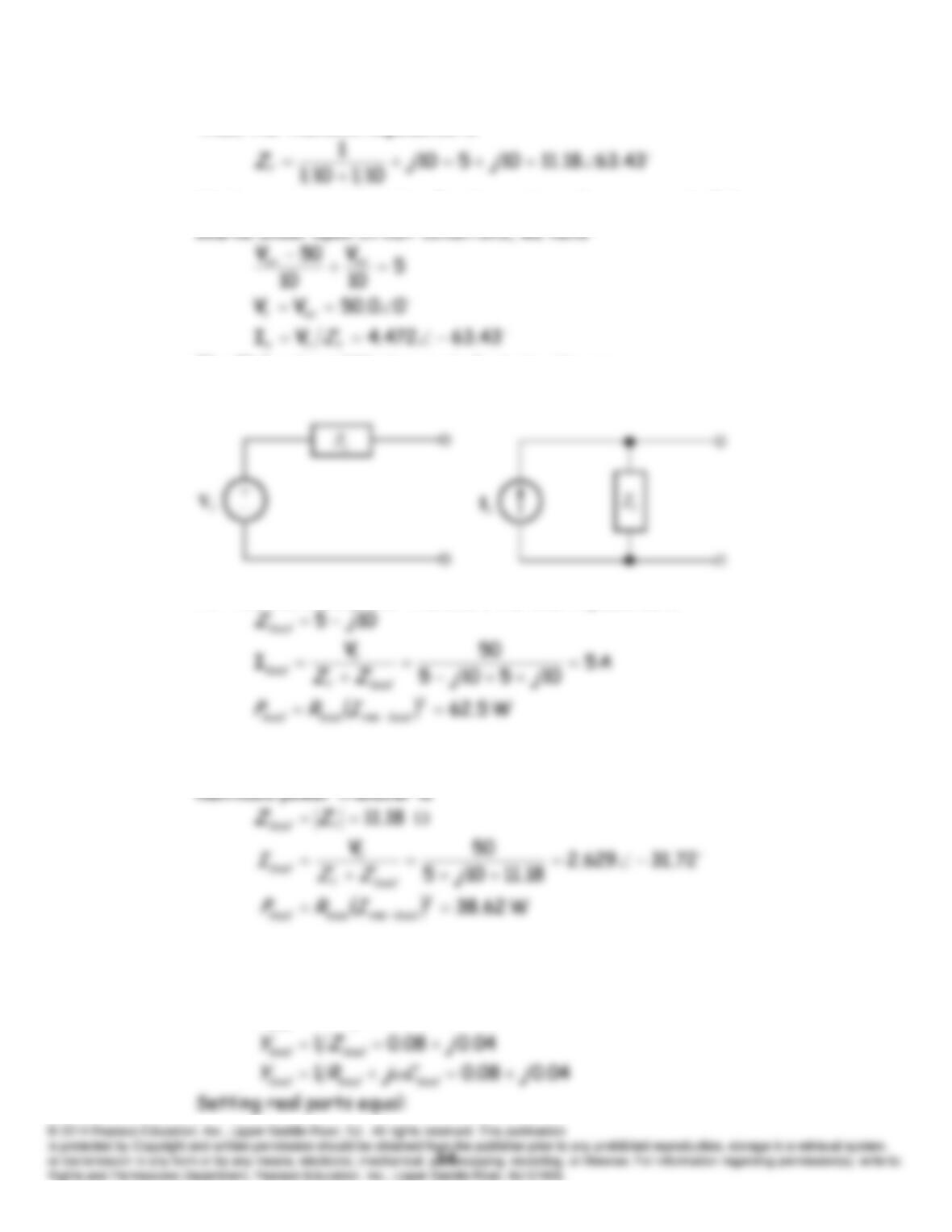
Thus, the Thévenin impedance is
Writing a current equation for the node at the upper end of the current
The Thévenin and Norton equivalent circuits are:
For the maximum power transfer, the load impedance is
In the case for which the load must be pure resistance, the load for
P5.87* For maximum power transfer, the impedance of the load should be the
complex conjugate of the Thévenin impedance:
510
jZ
load
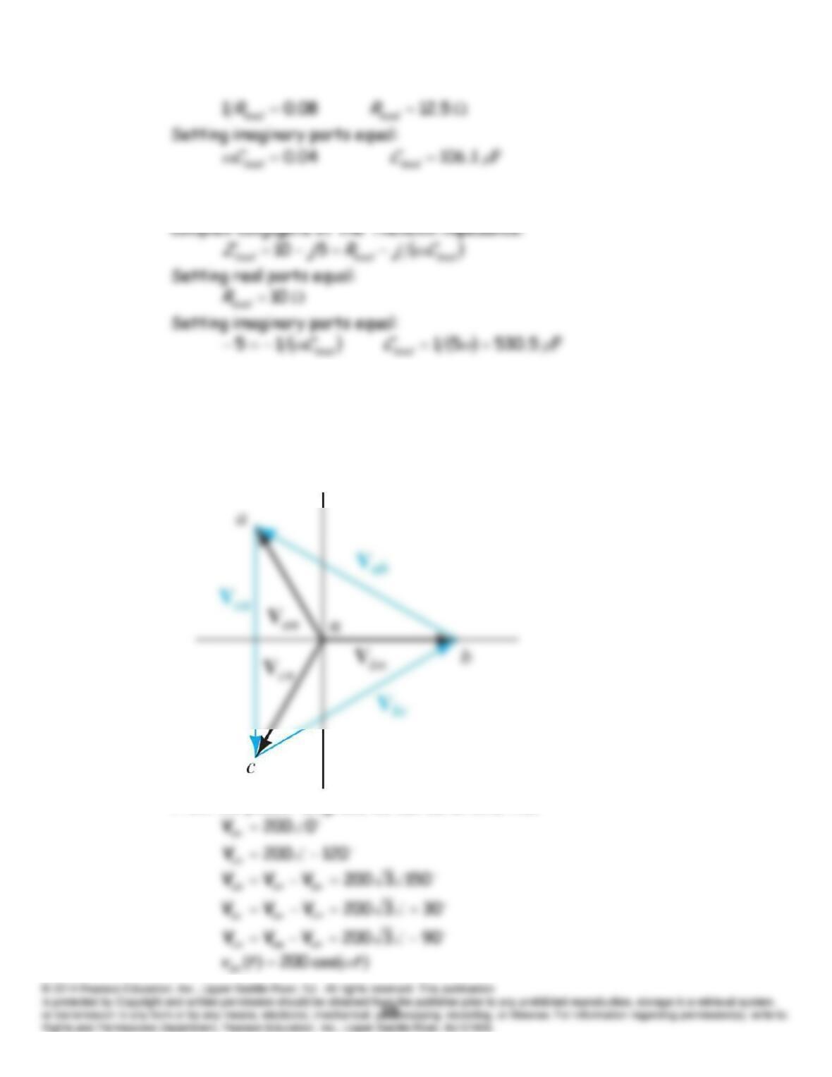
P5.88 For maximum power transfer, the impedance of the load should be the
P5.89 We are given:
120cos200
ttvan
and a positive-sequence source.
As a phasor
120200
an
V
. For counterclockwise rotation, the sequence
of phasors is abc.
The phasor diagram is:
From the phasor diagram, we can determine that