010660.8 αωω
n
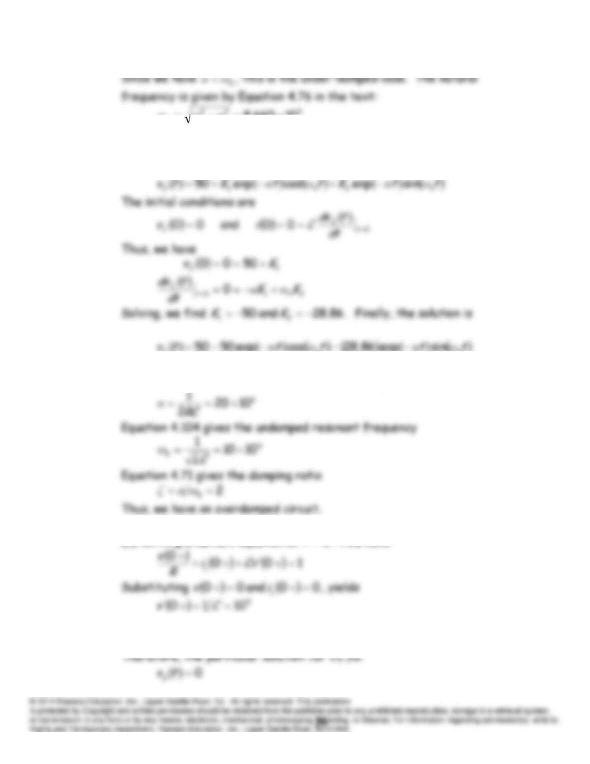
The complementary solution is given in Equation 4.77 in the text:
ttKttKtv nn
Cc
ωαωα sinexpcosexp 21
and the complete solution is
C
P4.64 (a) Using Equation 4.103 from the text, the damping coefficient is
(b) Writing a current equation at
0
t
, we have
(c) Under steady-state conditions, the inductance acts as a short circuit.
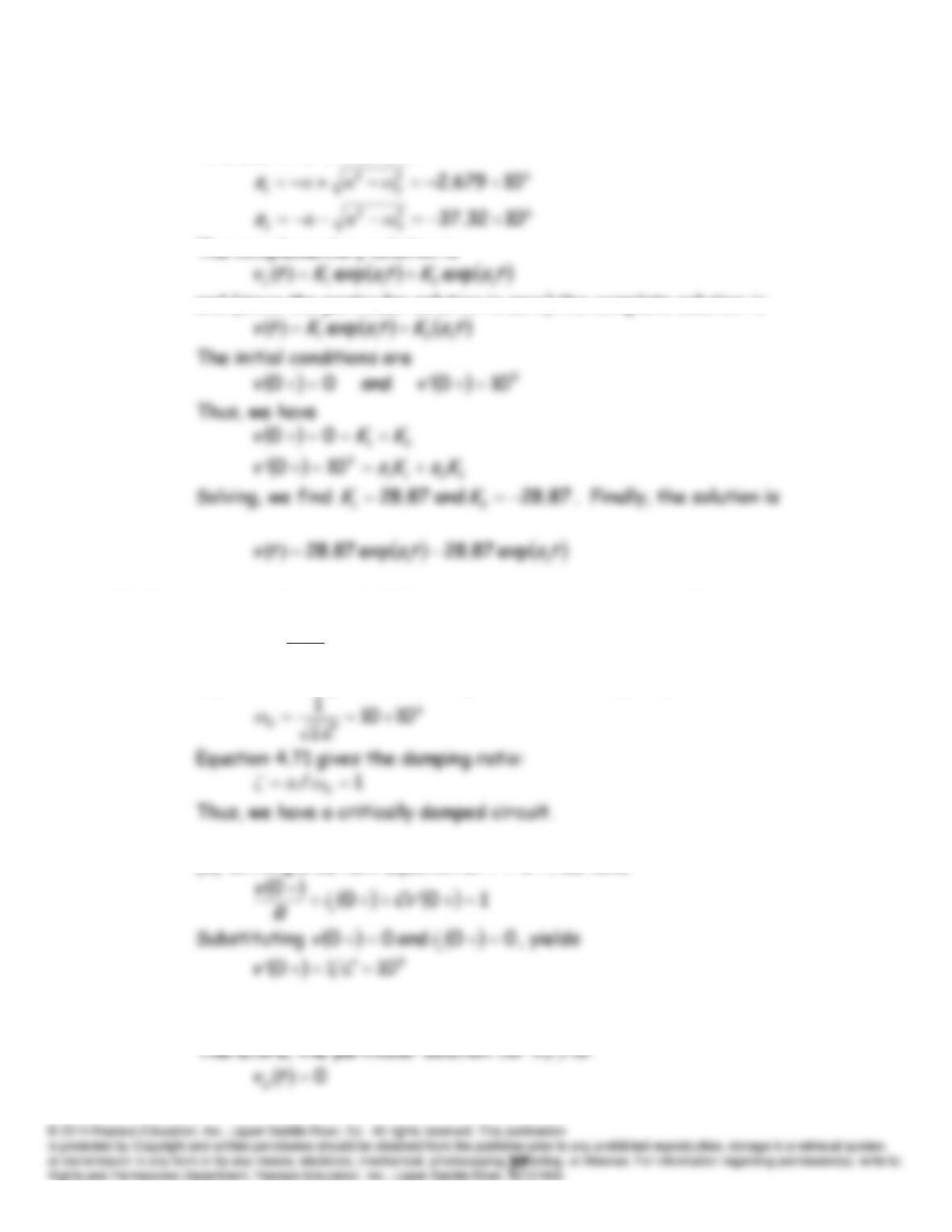
(d) The roots of the characteristic equation are found from Equations
4.72 and 4.73 in the text.
The complementary solution is
and (since the particular solution is zero) the complete solution is
P4.65 (a) Using Equation 4.103 from the text, the damping coefficient is
6
1010
2
1
RC
α
Equation 4.104 gives the undamped resonant frequency:
(b) Writing a current equation at
0
t
, we have
(c) Under steady-state conditions, the inductance acts as a short circuit.
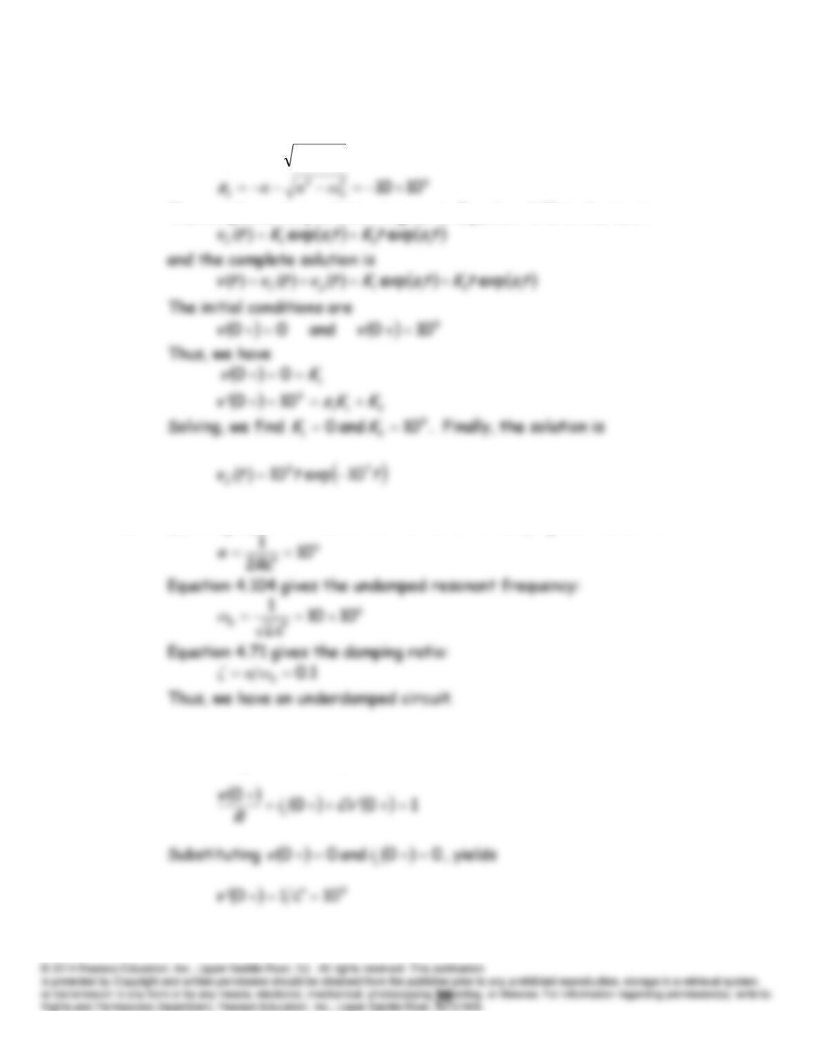
(d) The roots of the characteristic equation are found from Equations
4.72 and 4.73 in the text.
62
0
2
1
1010
ωαα
s
The complementary solution is given in Equation 4.75 in the text:
P4.66 (a) Using Equation 4.103 from the text, the damping coefficient is
(b) Writing a current equation at
0
t
, we have
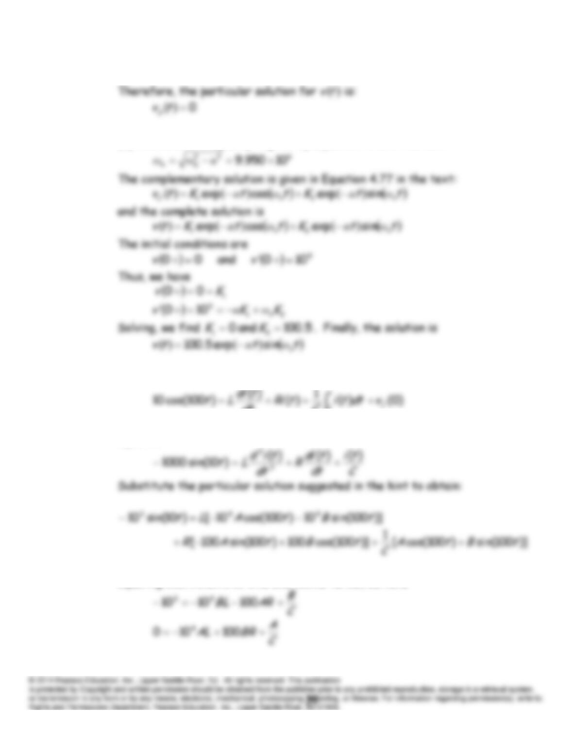
(c) Under steady-state conditions, the inductance acts as a short circuit.
(d) The natural frequency is given by Equation 4.76 in the text:
P4.67 Write a KVL equation for the circuit:
C
dt
0)0()(
Differentiate each term with respect to time to obtain a differential
equation:
Equating coefficients of sine and cosine terms, we have
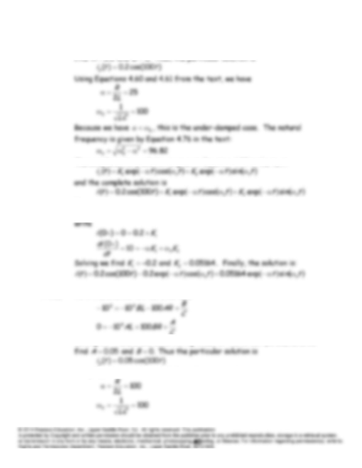
Solving for
A
and
B
and substituting values of the circuit parameters, we
find
2.0
A
and
.0
B
Thus, the particular solution is
The complementary solution is given in Equation 4.77 in the text:
However, because the current is zero at t = 0+, the voltage across the
inductor must be 10 V which implies that
.10/)0(
dtdi
Thus, we can
P4.68 As in the solution to P4.67, we have
C
Solving for
A
and
B
and substituting values of the circuit parameters, we
Using Equations 4.60 and 4.61 from the text, we have
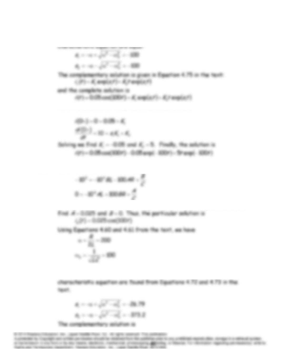
Since we have
0
ωα
,this is the critically damped case. The roots of the
As in the solution to P4.51, The initial conditions are
P4.69 As in the solution to P4.67, we have
C
Solving for
A
and
B
and substituting values of the circuit parameters, we
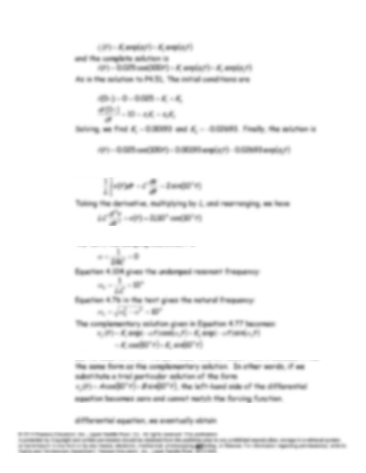
Since we have
0
ωα
, this is the overdamped case. The roots of the
P4.70 (a) Applying KCL, we have:
dt
(b) This is a parallel
RLC
circuit having
.
R
Using Equation 4.103 from
the text, the damping coefficient is
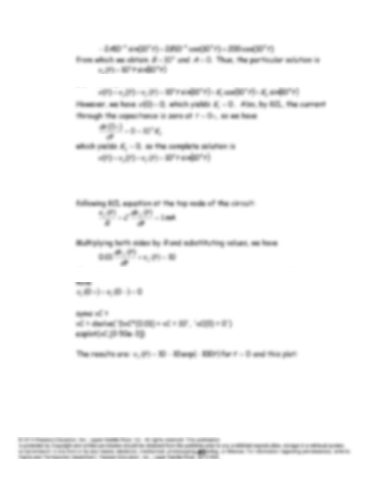
(c)The usual form for the particular solution doesn’t work because it has
(d) When we substitute
tBttAttv p
44 10sin10cos
into the
(e) The complete solution is
4.71 Note: We use
)(
tvtv C
in this solution. Prior to
0
t
, we have
0
tvC
because the switch is closed. After
0
t
, we can write the
The voltage across the capacitance cannot change instantaneously, so we
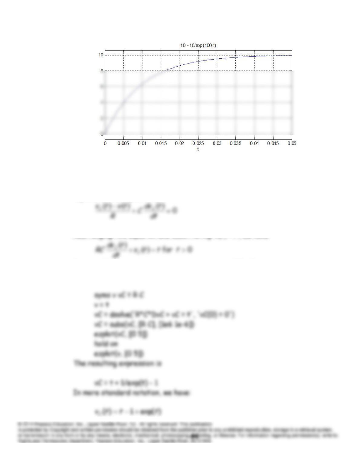
P4.72 The differential equation is obtained by applying KVL for the node at the
top end of the capacitance:
Rearranging this equation and substituting
ttv
, we have
Because the source is zero prior to zero time,
.0)0(
C
v
The MATLAB commands are
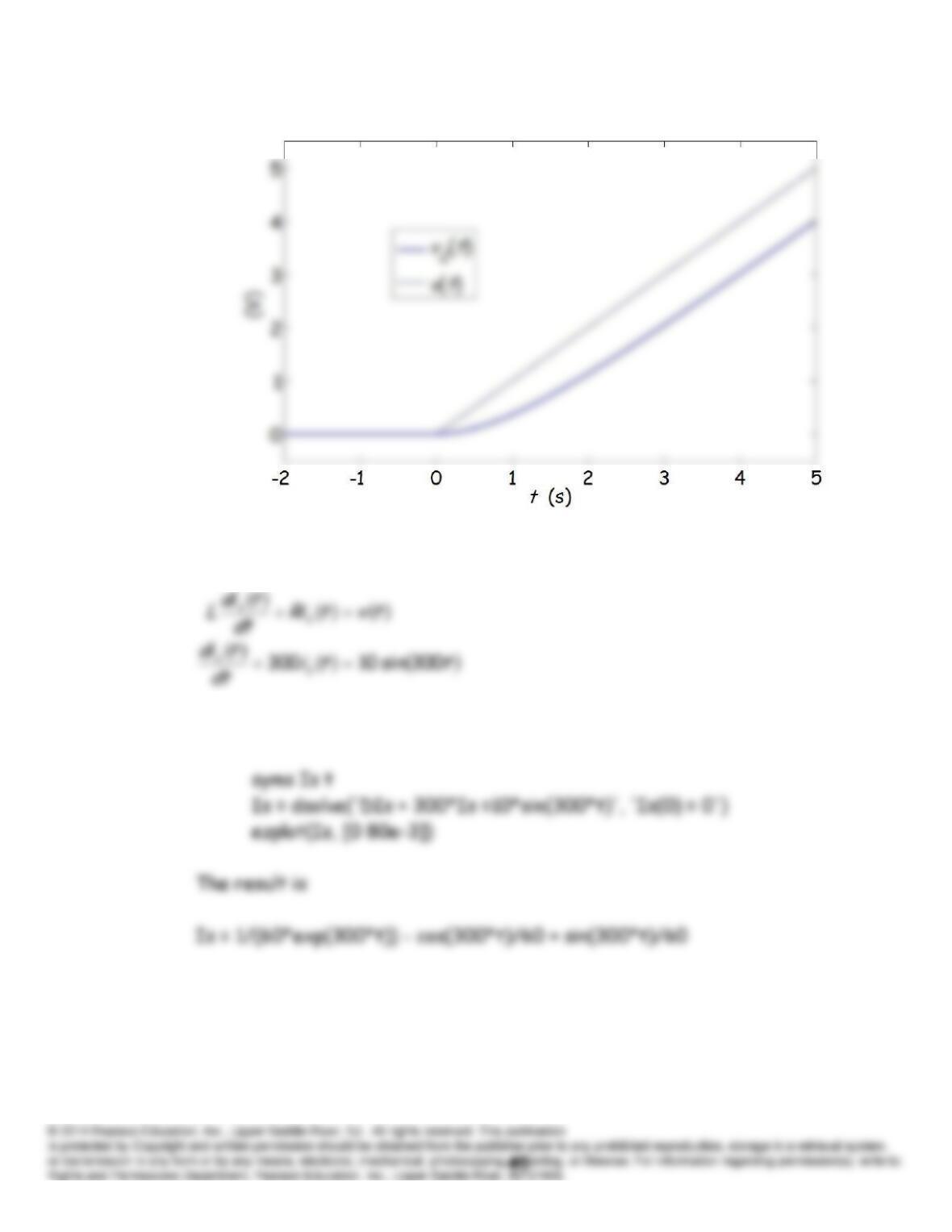
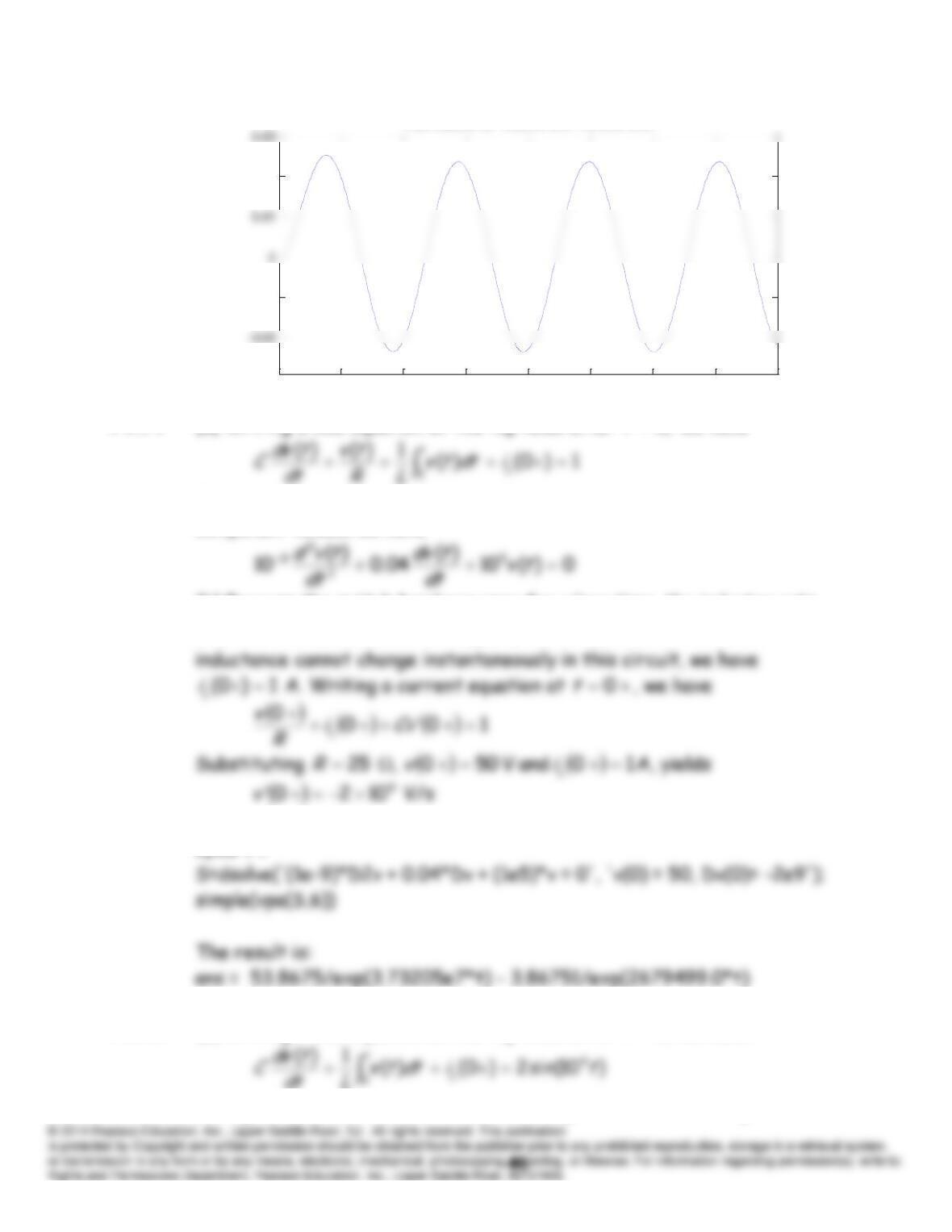
P4.73 Using KVL, we obtain the differential equation
The MATLAB commands are:
0 0.01 0.02 0.03 0.04 0.05 0.06 0.07 0.08
–0.01
0.02
t
1/(60 exp(300 t)) – cos(300 t)/60 + sin(300 t)/60
P4.74 (a) Writing a KCL equation at the top node after
,0
t
we have
Taking the derivative to eliminate the integral and substituting
component values, we have
(b) Because the switch has been open for a long time, the inductor acts
as a short circuit, and we have
1)0(
L
i
A. Because the current in the
L
i
(c) The MATLAB commands are:
syms v t
P4.75 (a) Writing a KCL equation at the top node after
,0
t
we have
Taking the derivative to eliminate the integral, and substituting
component values, we have
(b) Because the switch is closed prior to
,0
t
we know that
.0)0(
C
v
C
v
,0
t
(c) The MATLAB commands are:
syms v t
P4.76 The KVL equations around meshes 1 and 2 are
,0
t
Practice Test
T4.1 (a) Prior to the switch opening, the circuit is operating in DC steady
state, so the inductor acts as a short circuit, and the capacitor acts as an
open circuit.
(b) Because infinite voltage or infinite current are not possible in this
circuit, the current in the inductor and the voltage across the capacitor
(c) The current is of the form
)./exp()(
tBAtiL
Because the
(d) This is a case of an initially charged capacitance discharging through a
T4.2 (a)
)3exp(5)(
)(
2
tti
dt
tdi
have
T4.3 (a) Applying KVL to the circuit, we obtain
For the capacitance, we have
Using Equation (2) to substitute into Equation (1) and rearranging, we
(b) We try a particular solution of the form
AtvCp
, resulting in
(c) We have
T4.4 One set of commands is
syms vC t