Techniques of Circuit Analysis
Assessment Problems
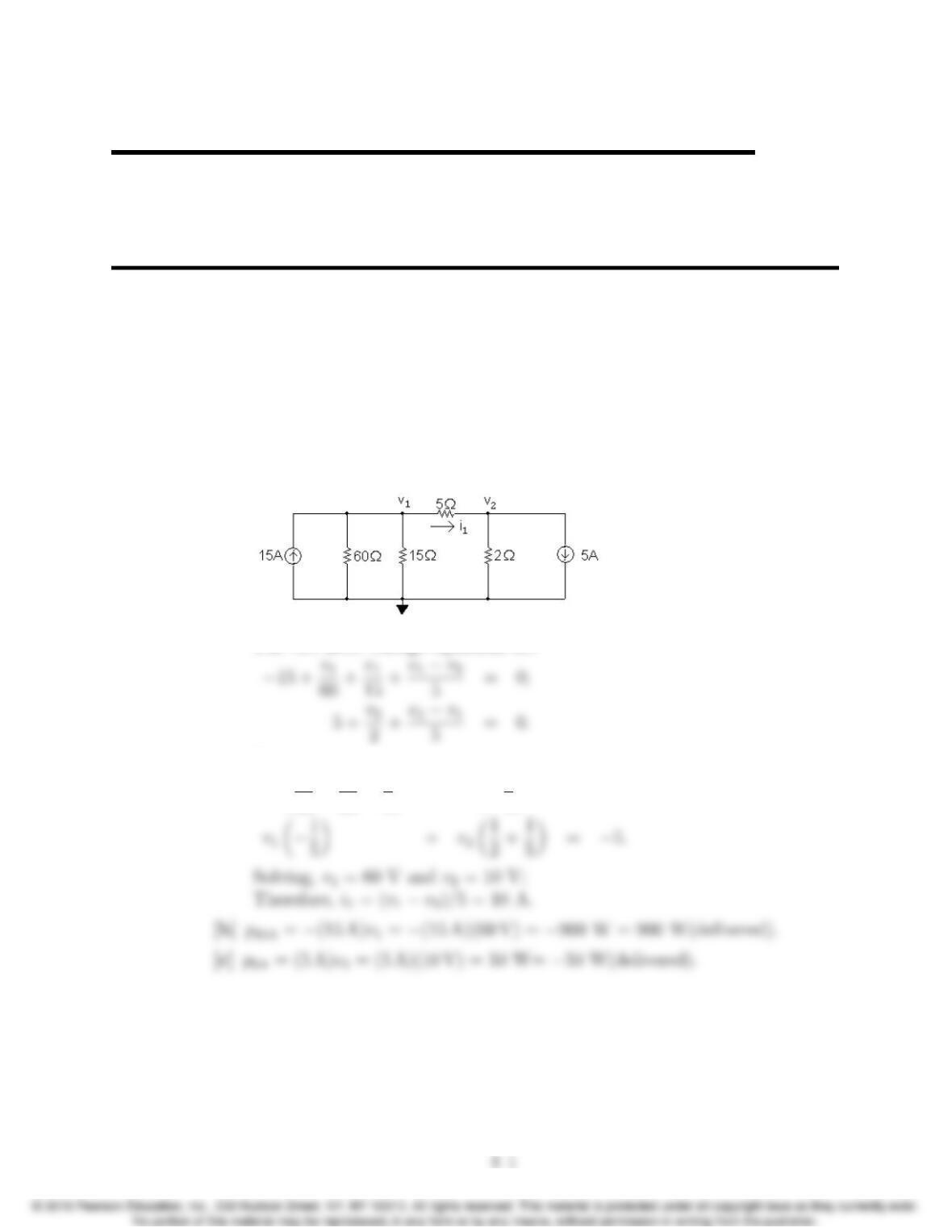
AP 4.1 [a] Redraw the circuit, labeling the reference node and the two node voltages:
The two node voltage equations are
Place these equations in standard form:
v1✓1
60 +1
15 +1
5◆+v2✓1
5◆= 15;
4
4–2 CHAPTER 4. Techniques of Circuit Analysis
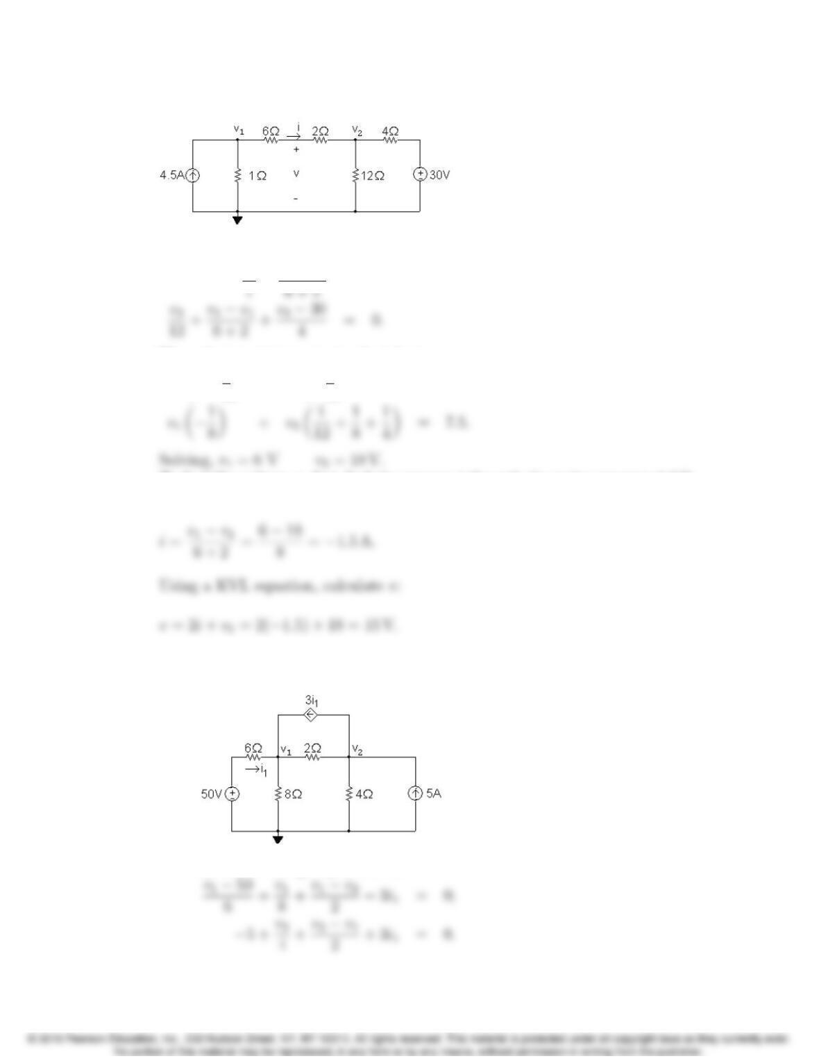
AP 4.2 Redraw the circuit, choosing the node voltages and reference node as shown:
The two node voltage equations are:
4.5+v1
Place these equations in standard form:
v1✓1+1
8◆+v2✓1
8◆=4.5;
To find the voltage v, first find the current ithrough the series-connected 6 Ω
and 2 Ωresistors:
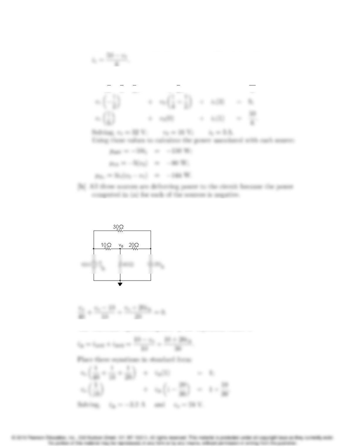
AP 4.3 [a] Redraw the circuit, choosing the node voltages and reference node as
shown:
The node voltage equations are:
Problems 4–3
The dependent source requires the following constraint equation:
Place these equations in standard form:
v1✓1
6+1
8+1
2◆+v2✓1
2◆+i1(3) = 50
6;
AP 4.4 Redraw the circuit and label the reference node and the node at which the
node voltage equation will be written:
The node voltage equation is
The constraint equation required by the dependent source is
4–4 CHAPTER 4. Techniques of Circuit Analysis
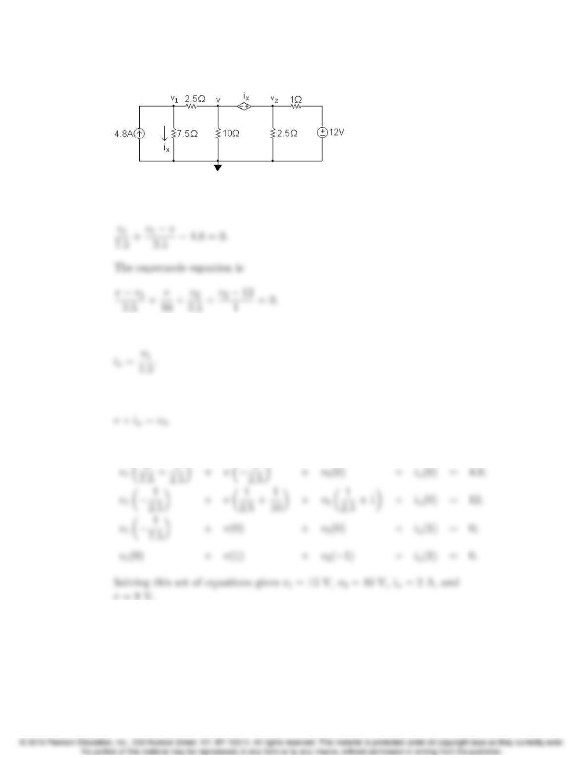
AP 4.5 Redraw the circuit identifying the three node voltages and the reference node:
Note that the dependent voltage source and the node voltages vand v2form a
supernode. The v1node voltage equation is
The constraint equation due to the dependent source is
The constraint equation due to the supernode is
Place this set of equations in standard form:
Problems 4–5
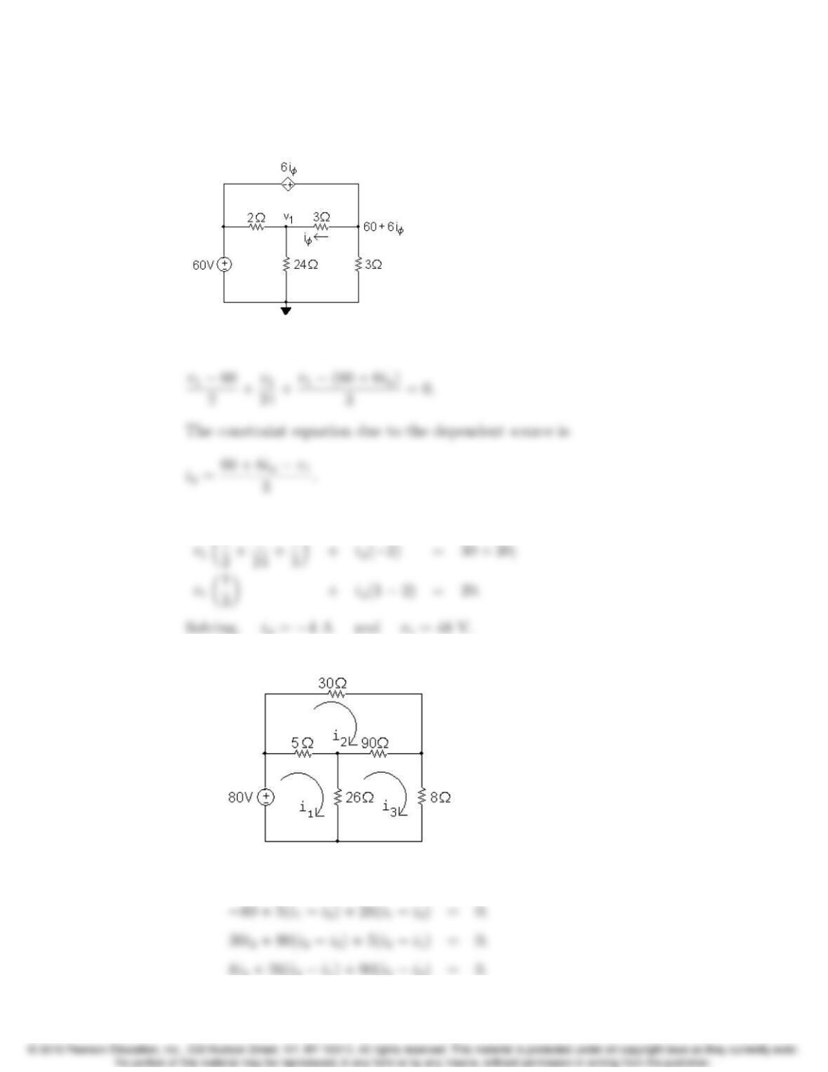
AP 4.6 Redraw the circuit identifying the reference node and the two unknown node
voltages. Note that the right-most node voltage is the sum of the 60 V source
and the dependent source voltage.
The node voltage equation at v1is
Place these two equations in standard form:
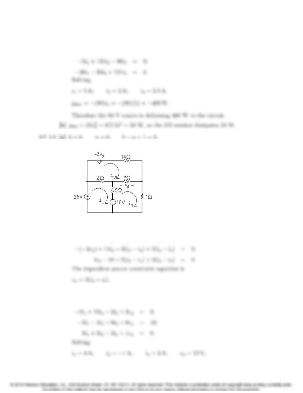
AP 4.7 [a] Redraw the circuit identifying the three mesh currents:
The mesh current equations are:
4–6 CHAPTER 4. Techniques of Circuit Analysis
Place these equations in standard form:
31i15i226i3= 80;
AP 4.8 [a] b= 8, n= 6, bn+ 1 = 3.
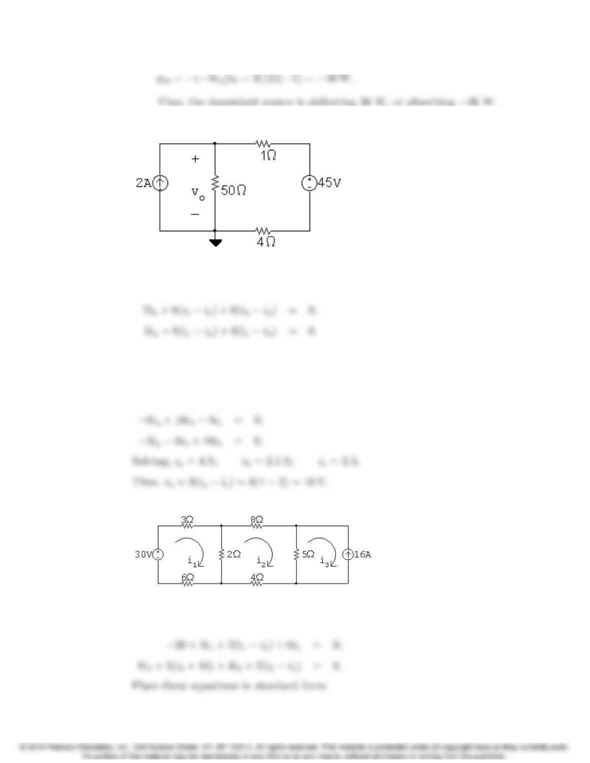
[b] Redraw the circuit identifying the three mesh currents:
The three mesh-current equations are
25 + 2(i1i2)+5(i1i3)+10 = 0;
Place these four equations in standard form:
7i12i25i3+0vφ= 15;
Problems 4–7
AP 4.9 Redraw the circuit identifying the three mesh currents:
The mesh current equations are:
25 + 6(iaib)+8(iaic) = 0;
The dependent source constraint equation is iφ=ia. We can substitute this
simple expression for iφinto the third mesh equation and place the equations
in standard form:
14ia6ib8ic= 25;
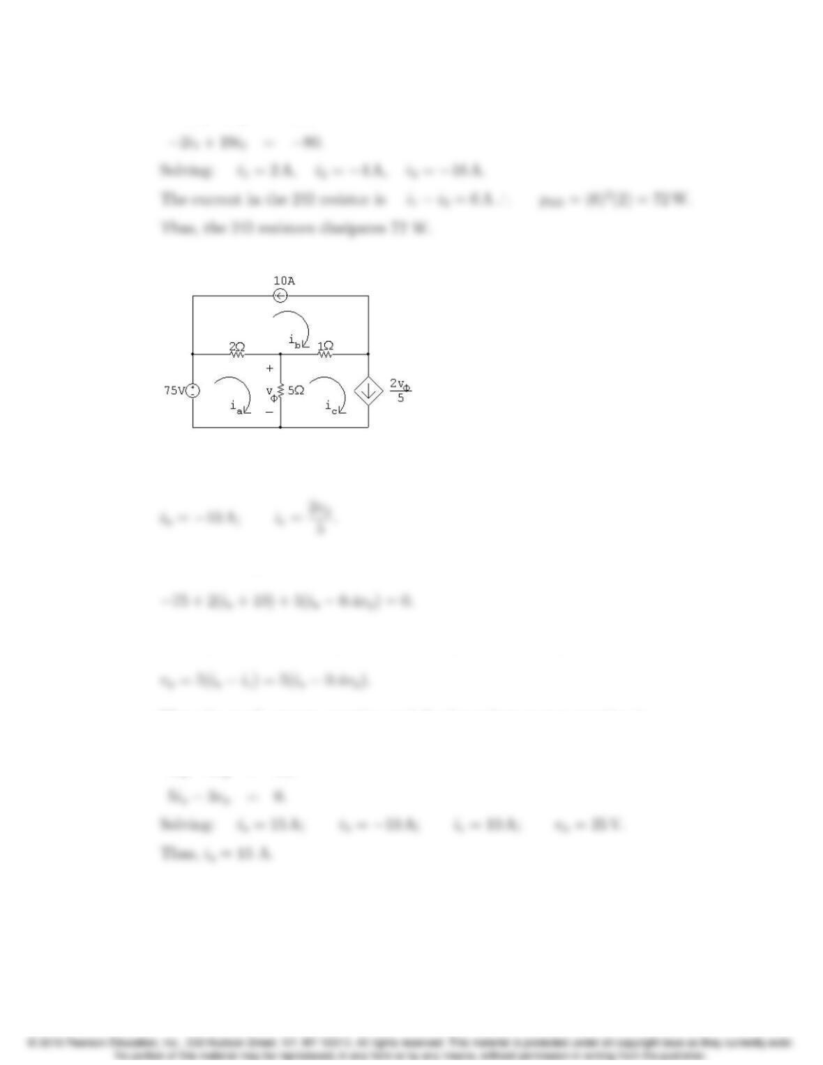
AP 4.10 Redraw the circuit identifying the mesh currents:
Since there is a current source on the perimeter of the i3mesh, we know that
i3=16 A. The remaining two mesh equations are
4–8 CHAPTER 4. Techniques of Circuit Analysis
11i12i2= 30;
AP 4.11 Redraw the circuit and identify the mesh currents:
There are current sources on the perimeters of both the ibmesh and the ic
mesh, so we know that
The remaining mesh current equation is
The dependent source requires the following constraint equation:
Place the mesh current equation and the dependent source equation is
standard form:
7ia2vφ= 55;
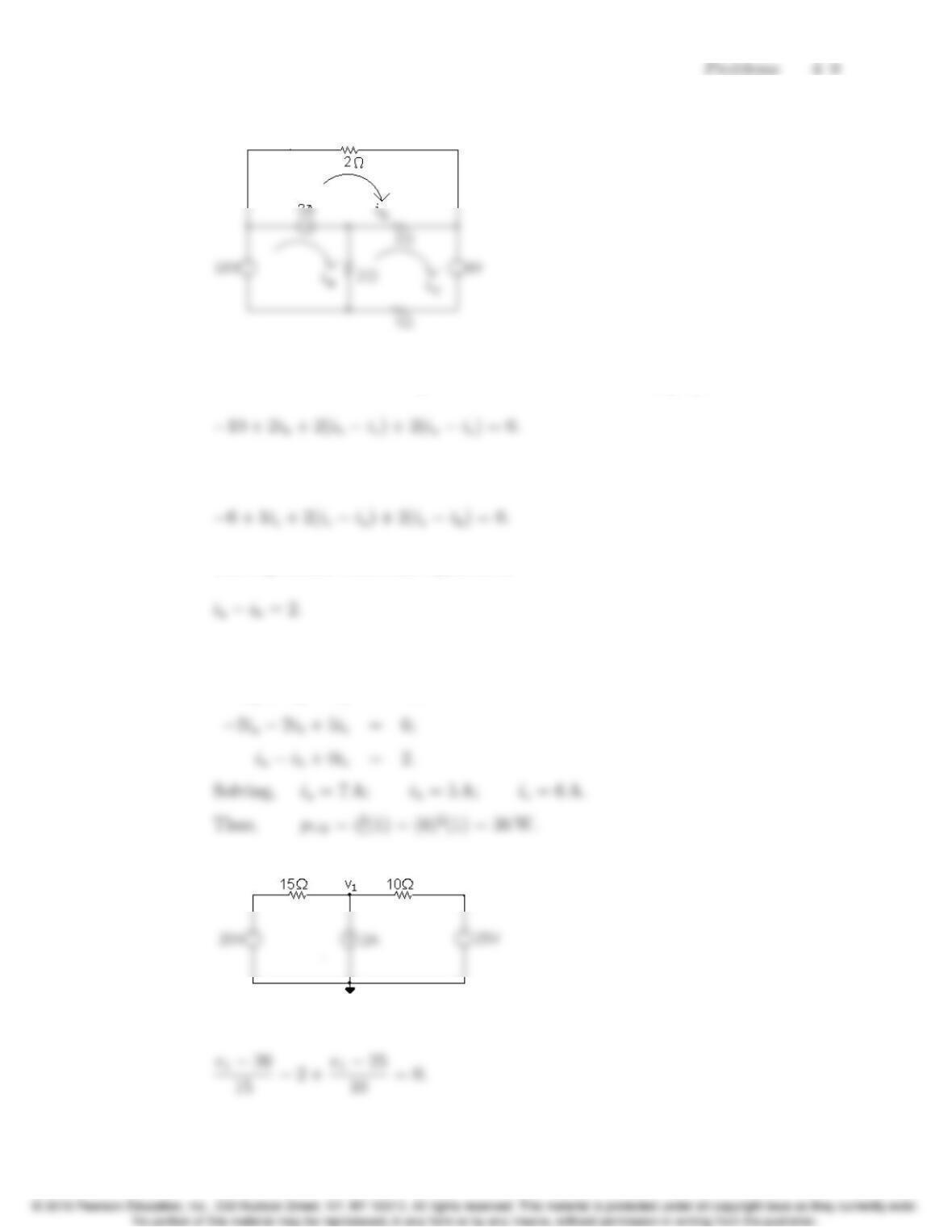
AP 4.12 Redraw the circuit and identify the mesh currents:
The 2 A current source is shared by the meshes iaand ib. Thus we combine
these meshes to form a supermesh and write the following equation:
The other mesh current equation is
The supermesh constraint equation is
Place these three equations in standard form:
2ia+4ib4ic= 10;
AP 4.13 Redraw the circuit and identify the reference node and the node voltage v1:
The node voltage equation is
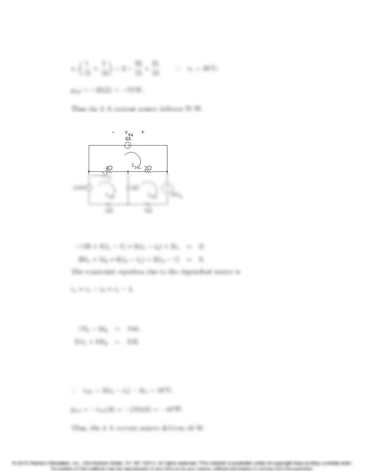
4–10 CHAPTER 4. Techniques of Circuit Analysis
Rearranging and solving,
AP 4.14 Redraw the circuit and identify the mesh currents:
There is a current source on the perimeter of the i3mesh, so i3= 4 A. The
other two mesh current equations are
Substitute the constraint equation into the second mesh equation and place
the resulting two mesh equations in standard form:
Solving,
i1= 9 A; i2=6 A; i3= 4 A; ix=94 = 5 A;
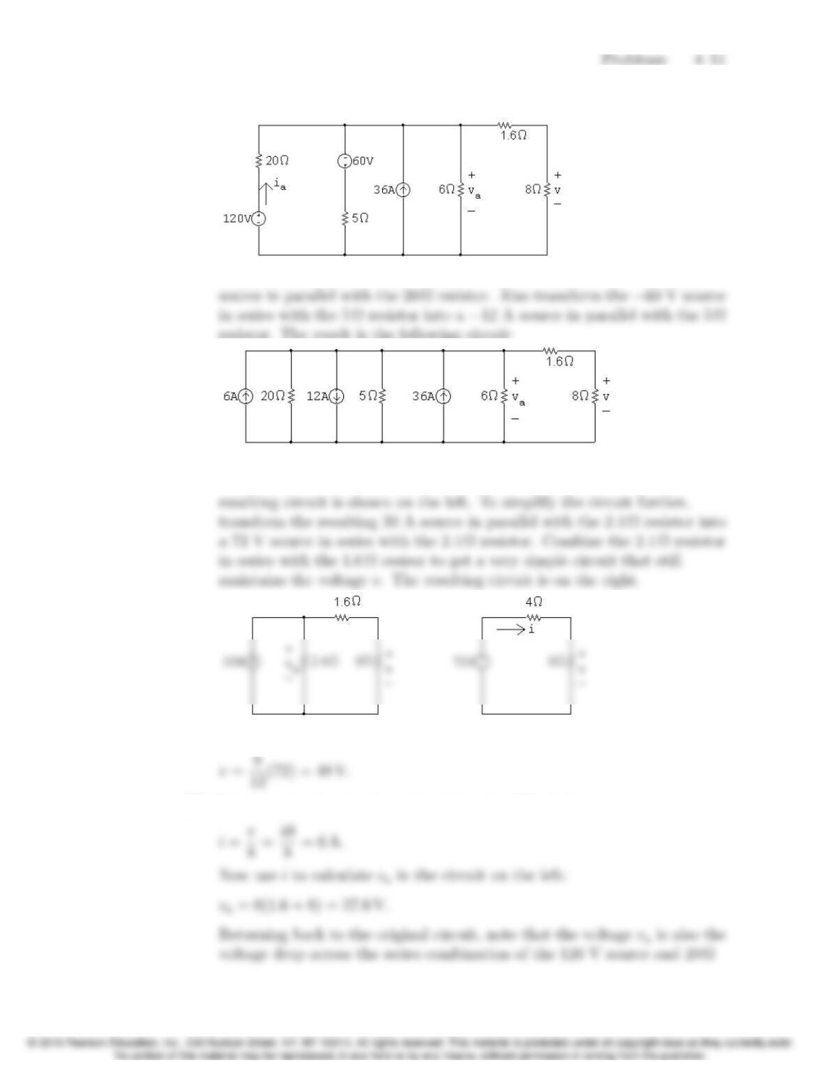
AP 4.15 [a] Redraw the circuit with a helpful voltage and current labeled:
Transform the 120 V source in series with the 20 Ωresistor into a 6 A
resistor. The result is the following circuit:
Combine the three current sources into a single current source, using
KCL, and combine the 20 Ω, 5 Ω, and 6 Ωresistors in parallel. The
Use voltage division in the circuit on the right to calculate vas follows:
[b] Calculate iin the circuit on the right using Ohm’s law:
4–12 CHAPTER 4. Techniques of Circuit Analysis
resistor. Use this fact to calculate the current in the 120 V source, ia:
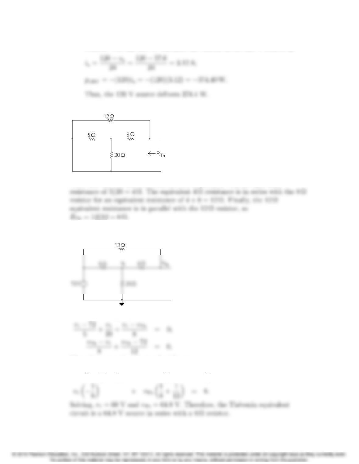
AP 4.16 To find RTh, replace the 72 V source with a short circuit:
Note that the 5 Ωand 20 Ωresistors are in parallel, with an equivalent
Use node voltage analysis to find vTh. Begin by redrawing the circuit and
labeling the node voltages:
The node voltage equations are
Place these equations in standard form:
v1✓1
5+1
20 +1
8◆+vTh ✓1
8◆=72
5;
Problems 4–13
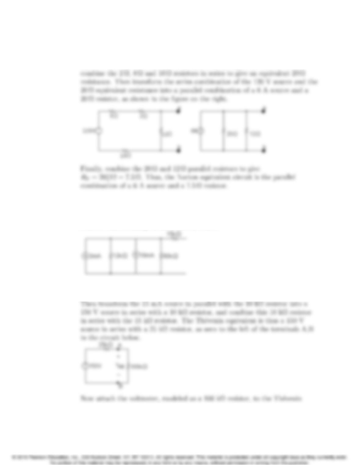
AP 4.17 We begin by performing a source transformation, turning the parallel
combination of the 15 A source and 8 Ωresistor into a series combination of a
120 V source and an 8 Ωresistor, as shown in the figure on the left. Next,
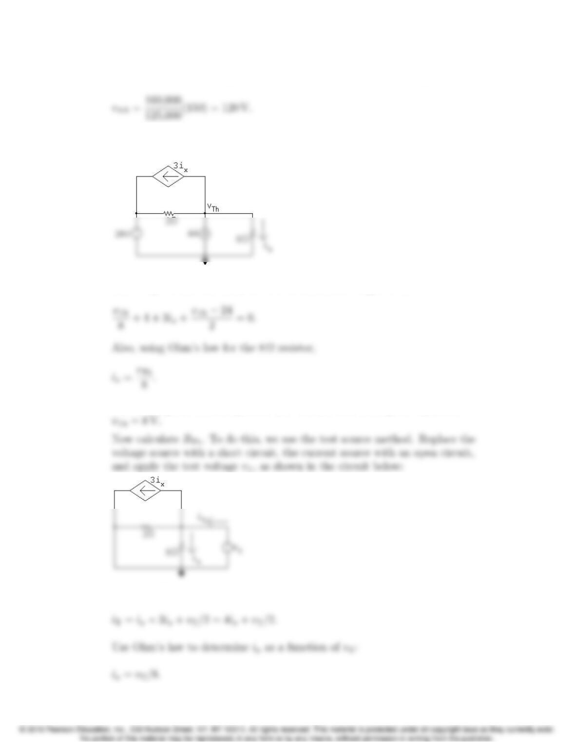
AP 4.18 Find the Th´evenin equivalent with respect to A, B using source
transformations. To begin, convert the series combination of the 36 V source
and 12 kΩresistor into a parallel combination of a 3 mA source and 12 kΩ
resistor. The resulting circuit is shown below:
Now combine the two parallel current sources and the two parallel resistors to
give a 3 + 18 = 15 mA source in parallel with a 12 kk60 k= 10 kΩresistor.
4–14 CHAPTER 4. Techniques of Circuit Analysis
equivalent and use voltage division to calculate the meter reading vAB:
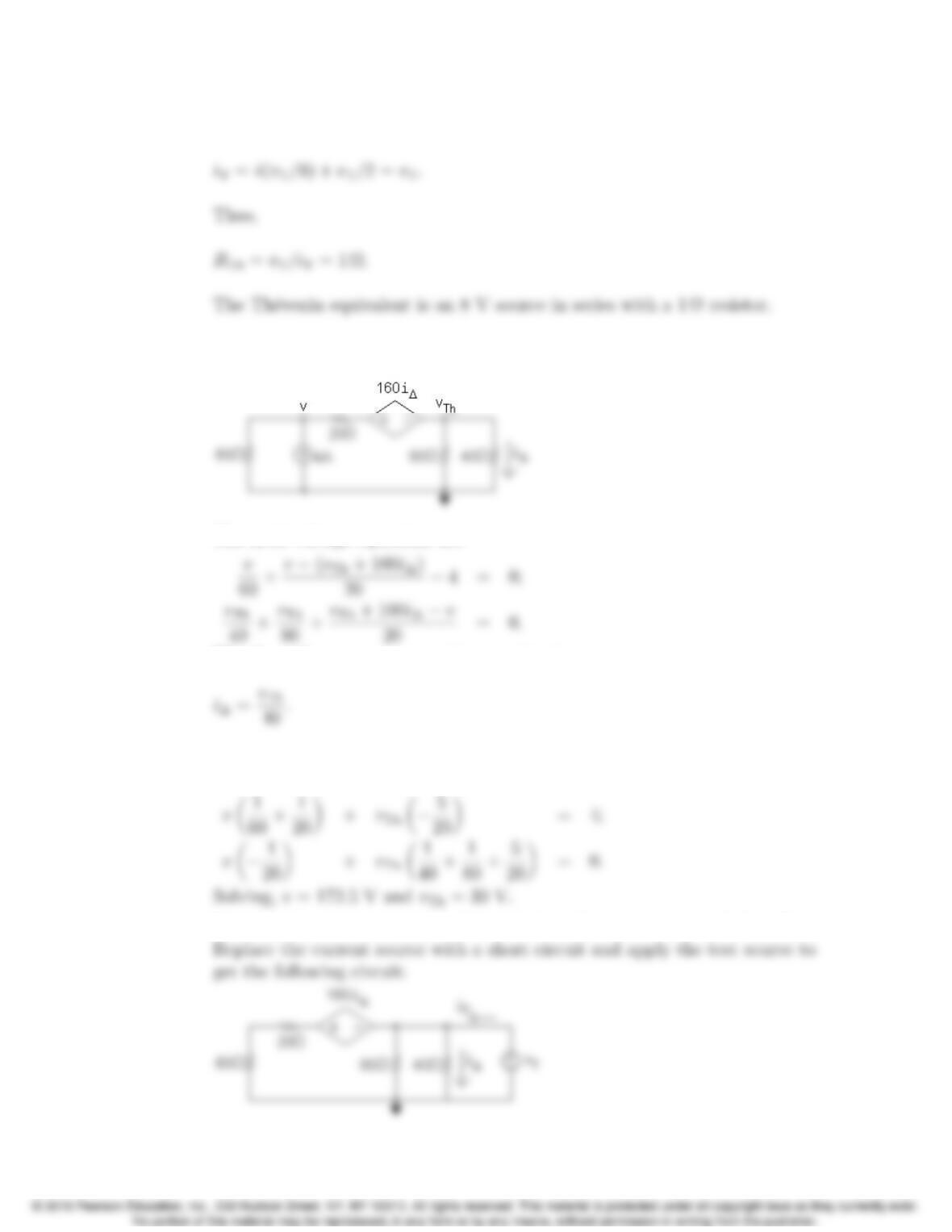
AP 4.19 Begin by calculating the open circuit voltage, which is also vTh, from the
circuit below:
Summing the currents away from the node labeled vTh We have
Substituting the second equation into the first and solving for vTh yields
Write a KCL equation at the middle node:
Problems 4–15
Substitute the second equation into the first equation:
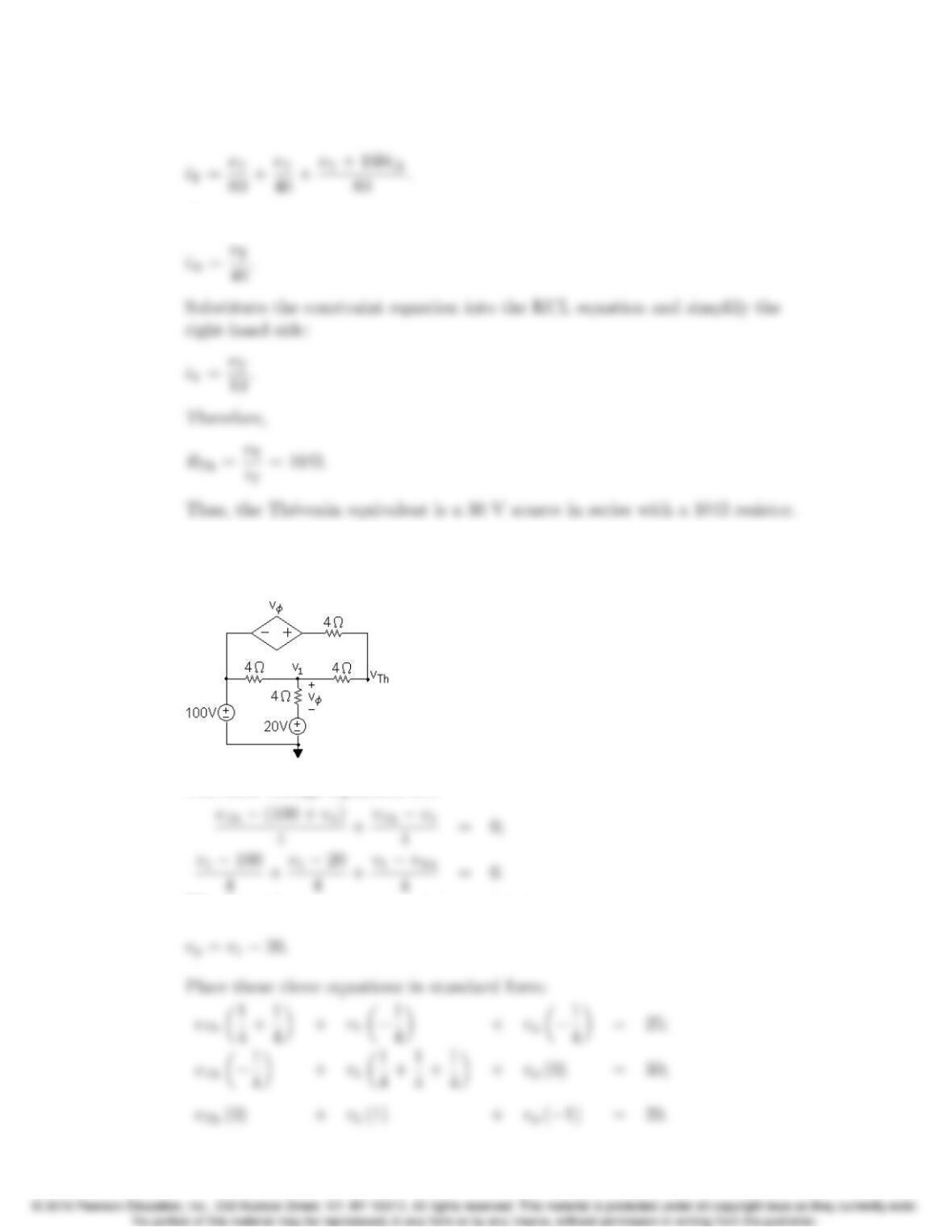
AP 4.20 Begin by calculating the open circuit voltage, which is also vTh, using the
node voltage method in the circuit below:
The node voltage equations are
The dependent source constraint equation is
Substitute the constraint equation into the node voltage equations and put the
two equations in standard form:
Now use the test source method to calculate the test current and thus RTh.
4–16 CHAPTER 4. Techniques of Circuit Analysis
Write a KCL equation at the rightmost node:
The dependent source constraint equation is
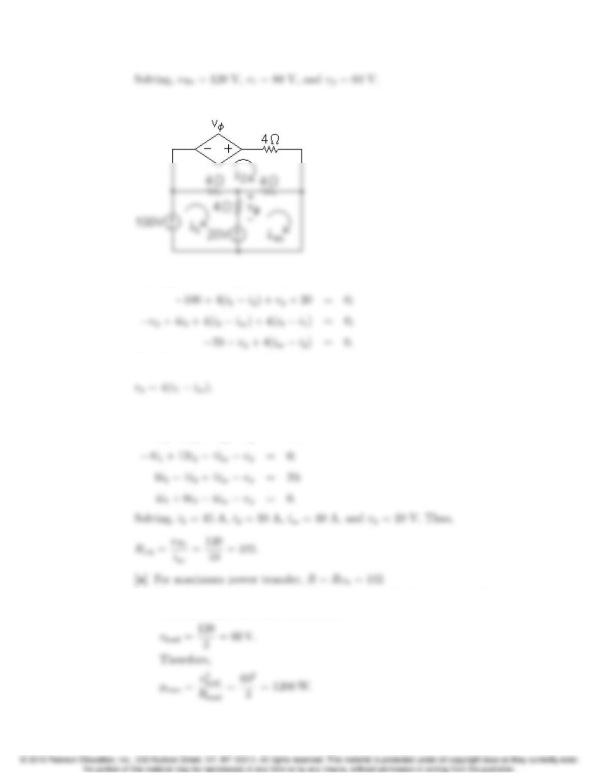
AP 4.21 First find the Th´evenin equivalent circuit. To find vTh, create an open circuit
between nodes a and b and use the node voltage method with the circuit
below:
The node voltage equations are:
The dependent source constraint equation is
Problems 4–17
Now create a short circuit between nodes a and b and use the mesh current
method with the circuit below:
The mesh current equations are
The dependent source constraint equation is
Place these four equations in standard form:
4i14i2+0isc +vφ= 80;
[b] The Th´evenin voltage, vTh = 120 V, splits equally between the Th´evenin
resistance and the load resistance, so
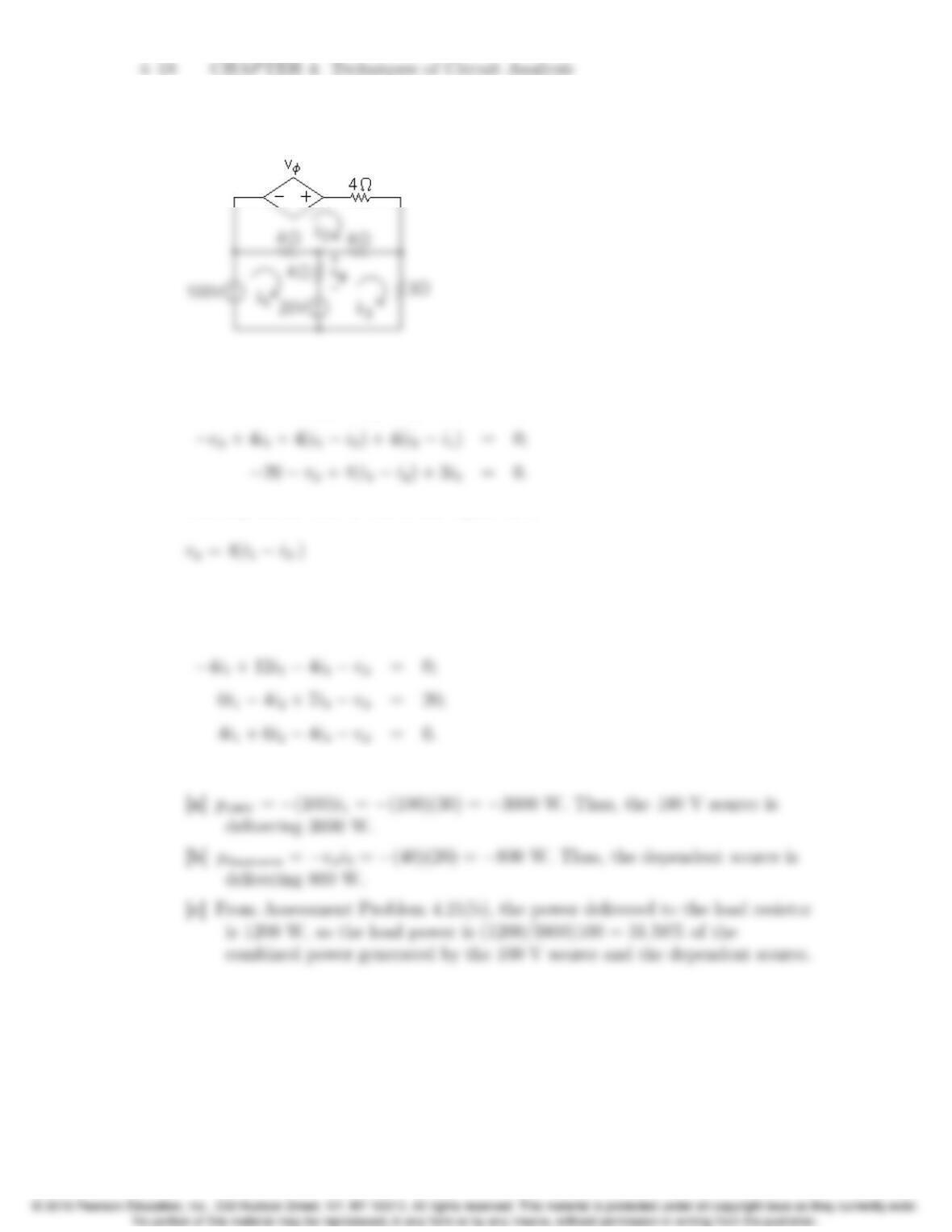
AP 4.22 Sustituting the value R= 3 Ωinto the circuit and identifying three mesh
currents we have the circuit below:
The mesh current equations are:
100 + 4(i1i2)+vφ+ 20 = 0;
The dependent source constraint equation is
Place these four equations in standard form:
4i14i2+0i3+vφ= 80;
Solving, i1= 30 A, i2= 20 A, i3= 20 A, and vφ= 40 V.
Problems 4–19
Problems
P 4.1
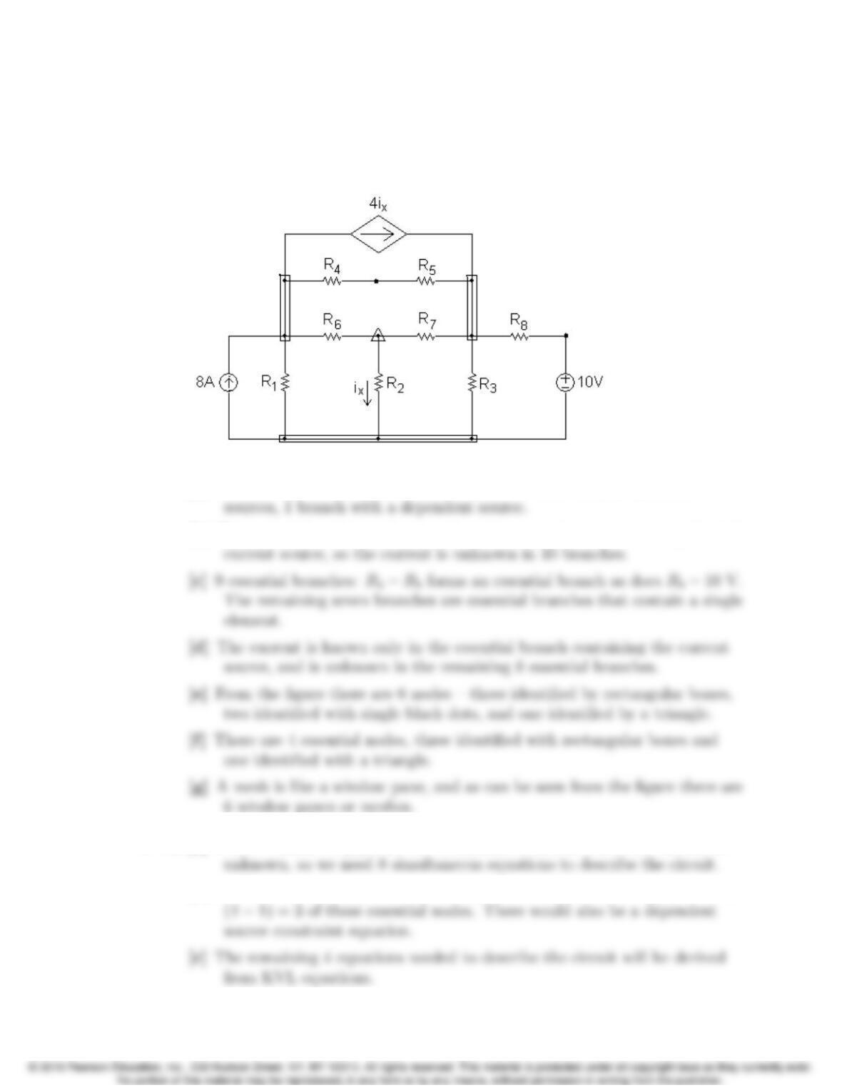
[a] 11 branches, 8 branches with resistors, 2 branches with independent
[b] The current is unknown in every branch except the one containing the 8 A
P 4.2 [a] From Problem 4.1(d) there are 8 essential branches where the current is
[b] From Problem 4.1(f), there are 4 essential nodes, so we can apply KCL at
4–20 CHAPTER 4. Techniques of Circuit Analysis
[d] We must avoid using the topmost mesh and the leftmost mesh. Each of
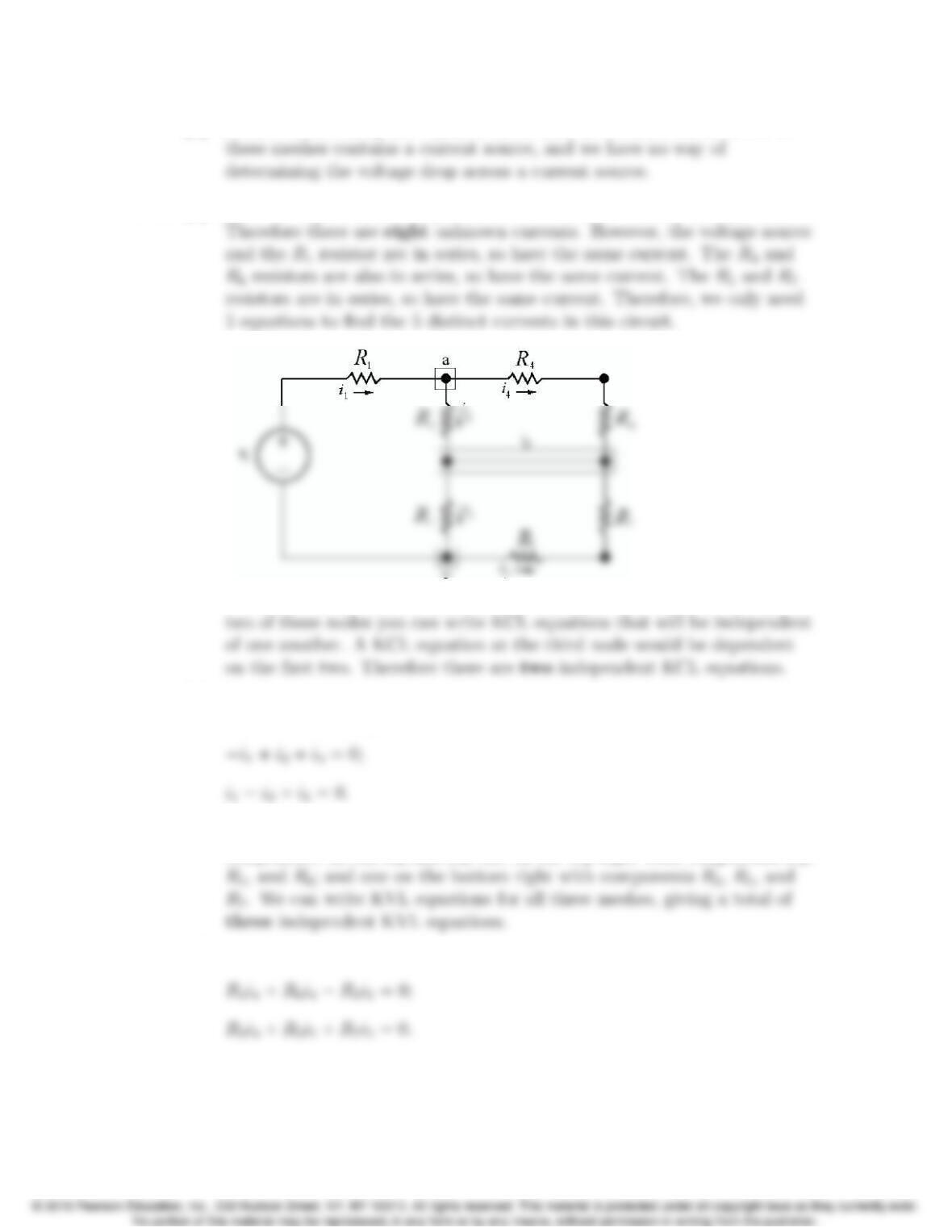
P 4.3 [a] There are eight circuit components, seven resistors and the voltage source.
[b]
There are three essential nodes in this circuit, identified by the boxes. At
[c] Sum the currents at any two of the three essential nodes a, b, and c. Using
nodes a and c we get
[d] There are three meshes in this circuit: one on the left with the
components vs,R1,R2and R3; one on the top right with components R2,
[e] vs+R1i1+R2i2+R3i3= 0;