CHAPTER 4
Exercises
E4.1 The voltage across the circuit is given by Equation 4.8:
)/exp()(
RCtVtv i
C
E4.2 The exponential transient shown in Figure 4.4 is given by
Taking the derivative with respect to time, we have
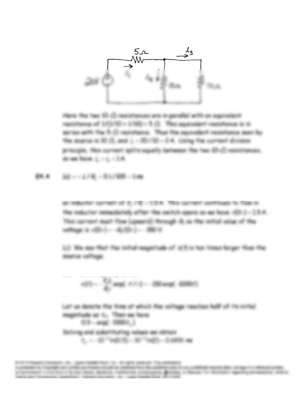
E4.3 (a) In dc steady state, the capacitances act as open circuits and the
inductances act as short circuits. Thus the steady-state (i.e.,
t
approaching infinity) equivalent circuit is:
(b) The dc steady-state equivalent circuit is:
(b) Just before the switch opens, the circuit is in dc steady state with
(d) The voltage is given by
E4.5 First we write a KCL equation for
.0
t
Taking the derivative of each term of this equation with respect to time
and multiplying each term by
R
, we obtain:
The solution to this equation is of the form:
Thus, we have
E4.6 Prior to
t
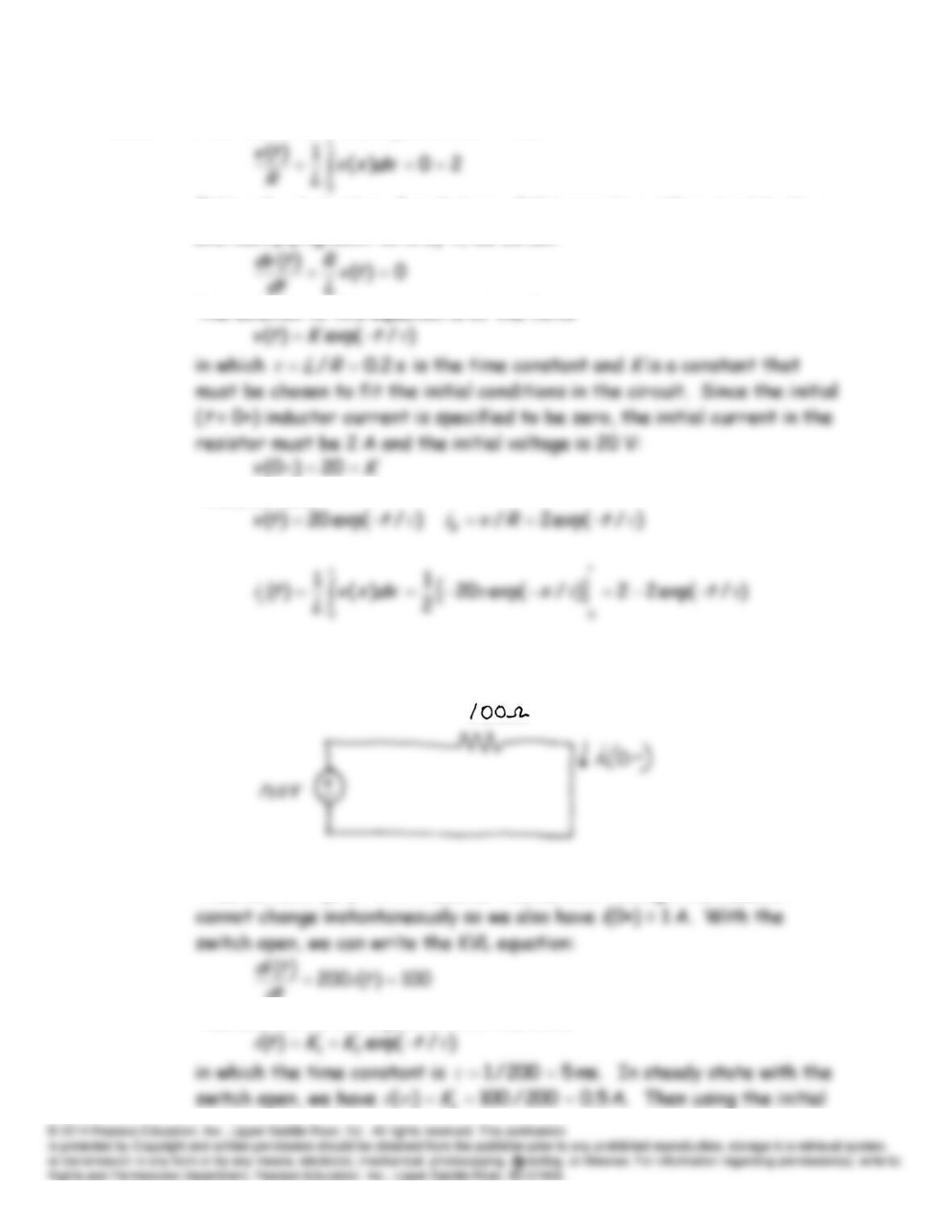
= 0, the circuit is in DC steady state and the equivalent circuit
is
Thus we have
i
(0-) = 1 A. However the current through the inductor
dt
The solution to this equation is of the form
.5.0
2
K
Thus we have
E4.7 As in Example 4.4, the KVL equation is
Taking the derivative and multiplying by C, we obtain
Substituting values and rearranging the equation becomes
The particular solution is of the form
Equating the coefficients of the cos and sin terms gives the following
equations:
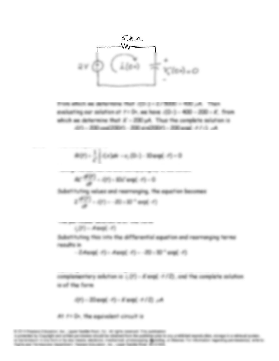
E4.8 The KVL equation is
Taking the derivative and multiplying by C, we obtain
Equating the coefficients gives
.1020 6
A
Furthermore, the
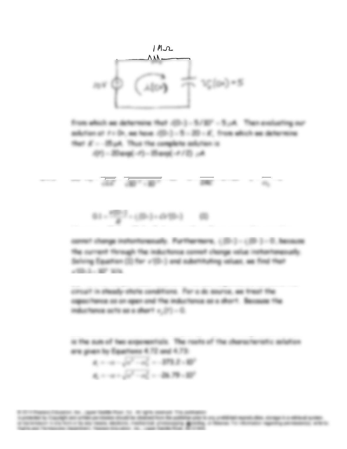
E4.9 (a)
5
11
5
102
1
2
(b) At
t
= 0+, the KCL equation for the circuit is
However,
0)0()0(
vv
, because the voltage across the capacitor
10)0(
v
V/s.
(c) To find the particular solution or forced response, we can solve the
(d) Because the circuit is overdamped
),1(
the homogeneous solution
Adding the particular solution to the homogeneous solution gives the
general solution:
E4.10 (a)
5
11
5
10
1
1
(c) The solution for this part is the same as that for Exercise 4.9c in
(d) The roots of the characteristic solution are given by Equations 4.72
E4.11 (a)
5
11
4
102
1
0.2
(d) Because we have
),1(
this is the underdamped case and we have
E4.12 The commands are:
syms ix t R C vCinitial w
E4.13 The commands are:
syms vc t
vpa(vc,4)
Problems
P4.1 The time constant
τ
is the interval required for the voltage to fall to
P4.2 We have
)/exp(
tVtv i
and
)()( 2
2
1
tCvtw
in which
Vi
is the initial
P4.3 The solution is of the form given in Equation 4.19:
Thus, we have
P4.4* The solution is of the form of Equation 4.17:
P4.5* The voltage across the capacitor is given by Equation 4.8.
)/exp(
RCtVtv i
in which
100
i
V
V is the initial voltage,
C
= 100
μ
F is the capacitance,
and
R
is the leakage resistance.
The energy stored in the capacitance is
P4.6 The voltage across the capacitor is given by Equation 4.8.
)/exp(
RCtVtv i
P4.7 (a)
(c)
(d) The initial energy stored in the capacitance is
P4.8 Equation 4.8 gives the expression for the voltage across a capacitance
discharging through a resistance:
P4.9 Prior to
0
t
, we have
0
tv
because the switch is closed. After
ms 20
RC
dttpW R
The solution is of the form
The voltage across the capacitance cannot change instantaneously, so we
have
Thus,
10
KK
, and the solution is
P4.10* The initial energy is
P4.11* This is a case of a capacitance discharging through a resistance. The
voltage is given by Equation 4.8:
P4.12 We have
)/exp()97.0(
tPPP i
t
i
in which
t
is time in years,
Pi
is the
initial purchasing power and is the time constant in years. Solving we
have
P4.13 During the charging interval, the time constant is
10
11
CR
s, and the
voltage across the capacitor is given by
The time constant during the discharge interval is
20
22
CR
s.
Working in terms of the time variable
,25
tt
the voltage during the
discharge interval is
P4.15 The voltage across the resistance and capacitance is
ii CVQ
The current through the resistance is
P4.17 The final voltage for each 1 s interval is the initial voltage for the
succeeding interval.
P4.18 (a) The voltages across the capacitors cannot change instantaneously.
(b) Applying KVL, we have
(d) The solution to Equation (1) is of the form
(e) The final value of
tv
2
is
P4.19 For a dc steady-state analysis:
P4.20 In dc steady state conditions, the voltages across the capacitors are
constant. Therefore, the currents through the capacitances, which are
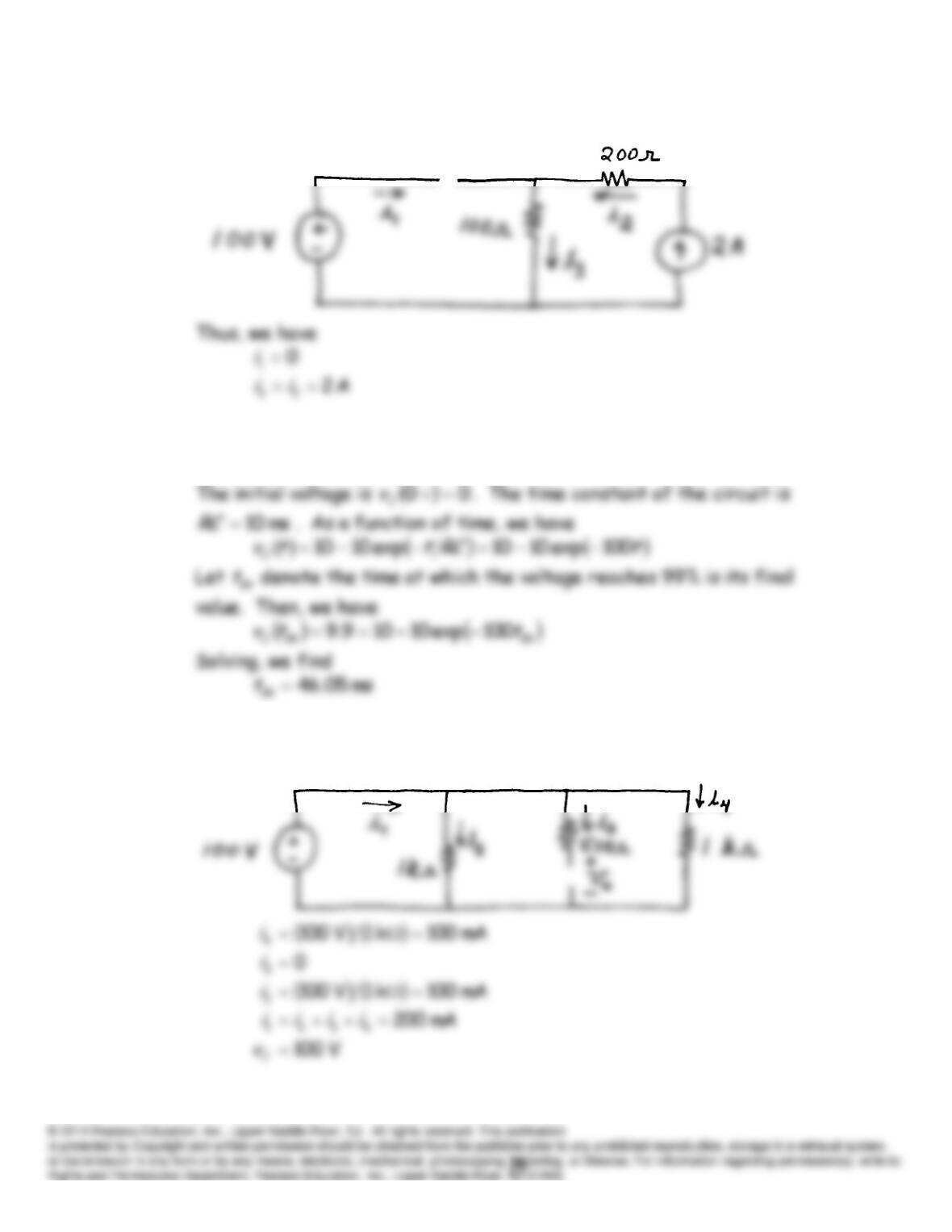
P4.21* In steady state, the equivalent circuit is:
P4.22* After the switch opens and the circuit reaches steady state, the 10-mA
current flows through the 1-k
resistance, and the voltage is 10 V.
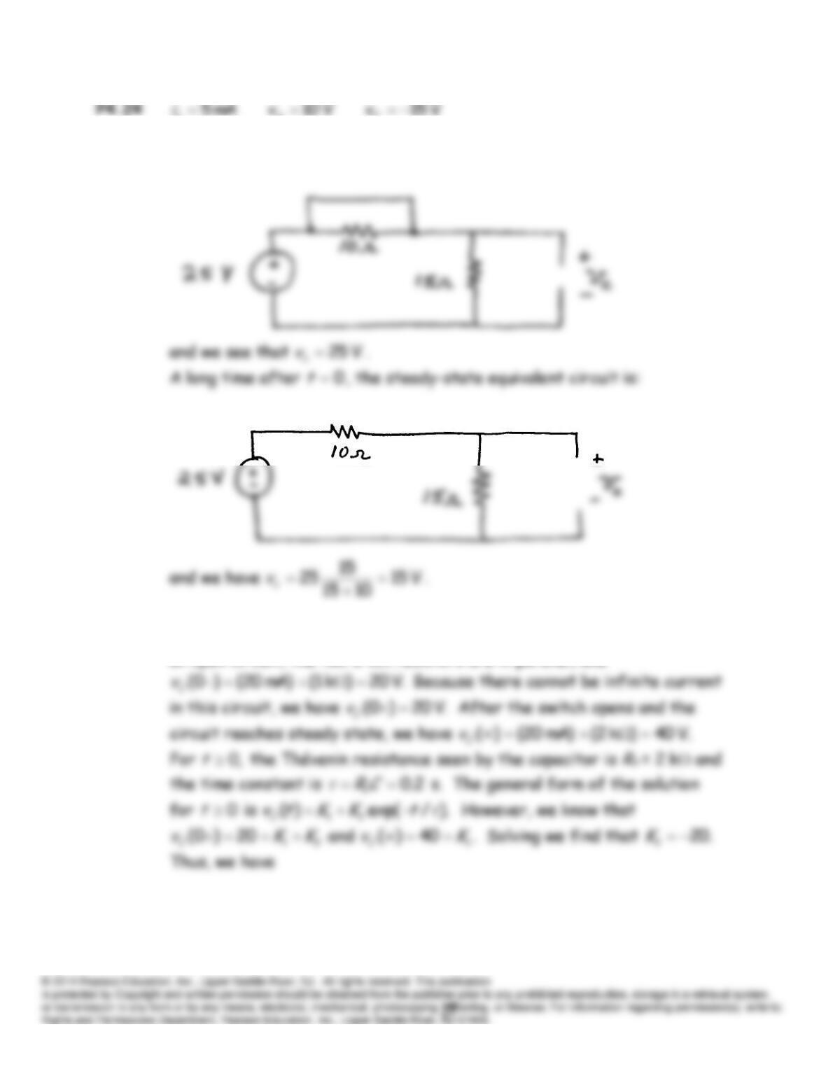
P4.23 In steady state with a dc source, the inductance acts as a short circuit
and the capacitance acts as an open circuit. The equivalent circuit is:
L
x
C
P4.25 Prior to
0
t
, the steady-state equivalent circuit is:
0
t
P4.26 With the circuit in steady state prior to
,0
t
the capacitor behaves as
an open circuit, the two 2-k resistors are in parallel, and
t
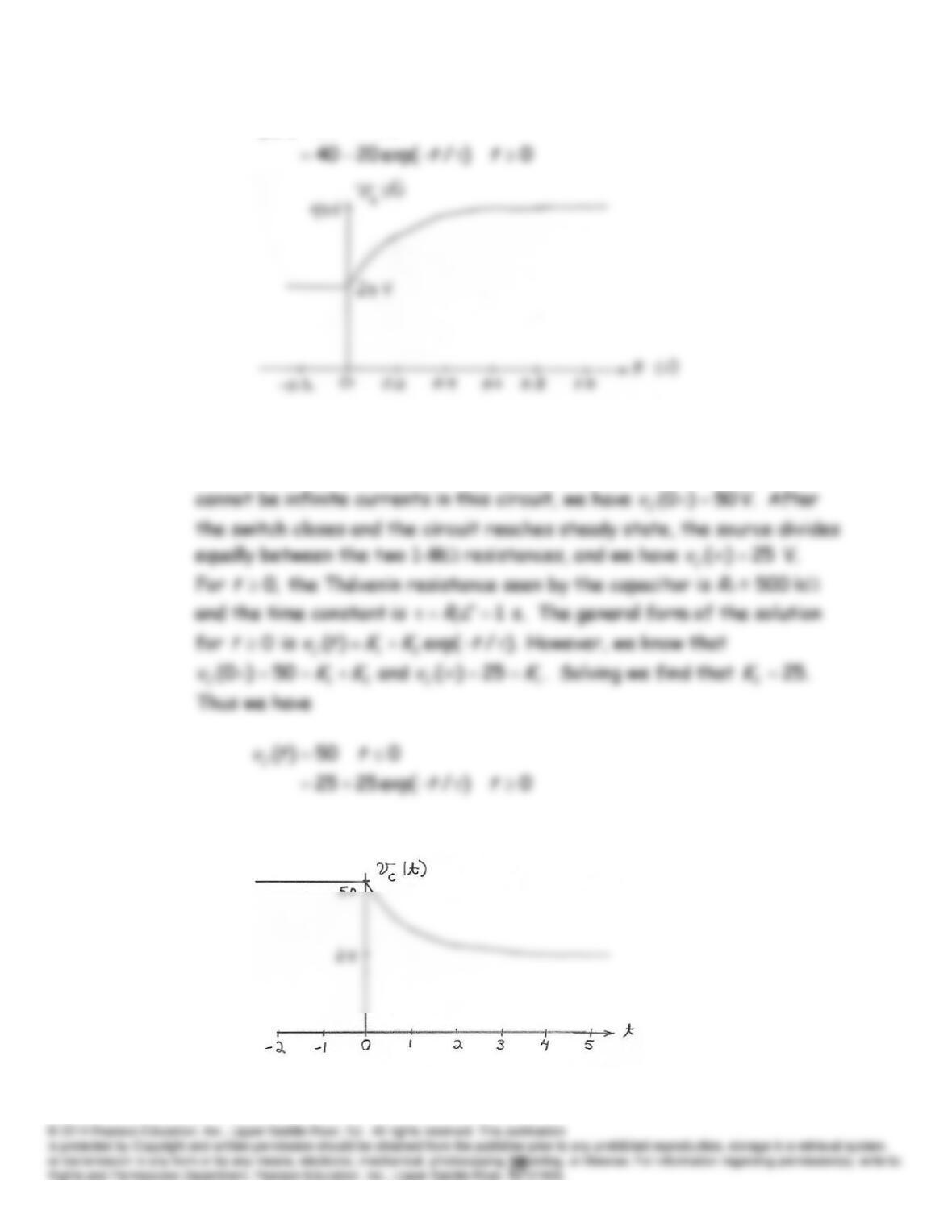
020)(
ttvC
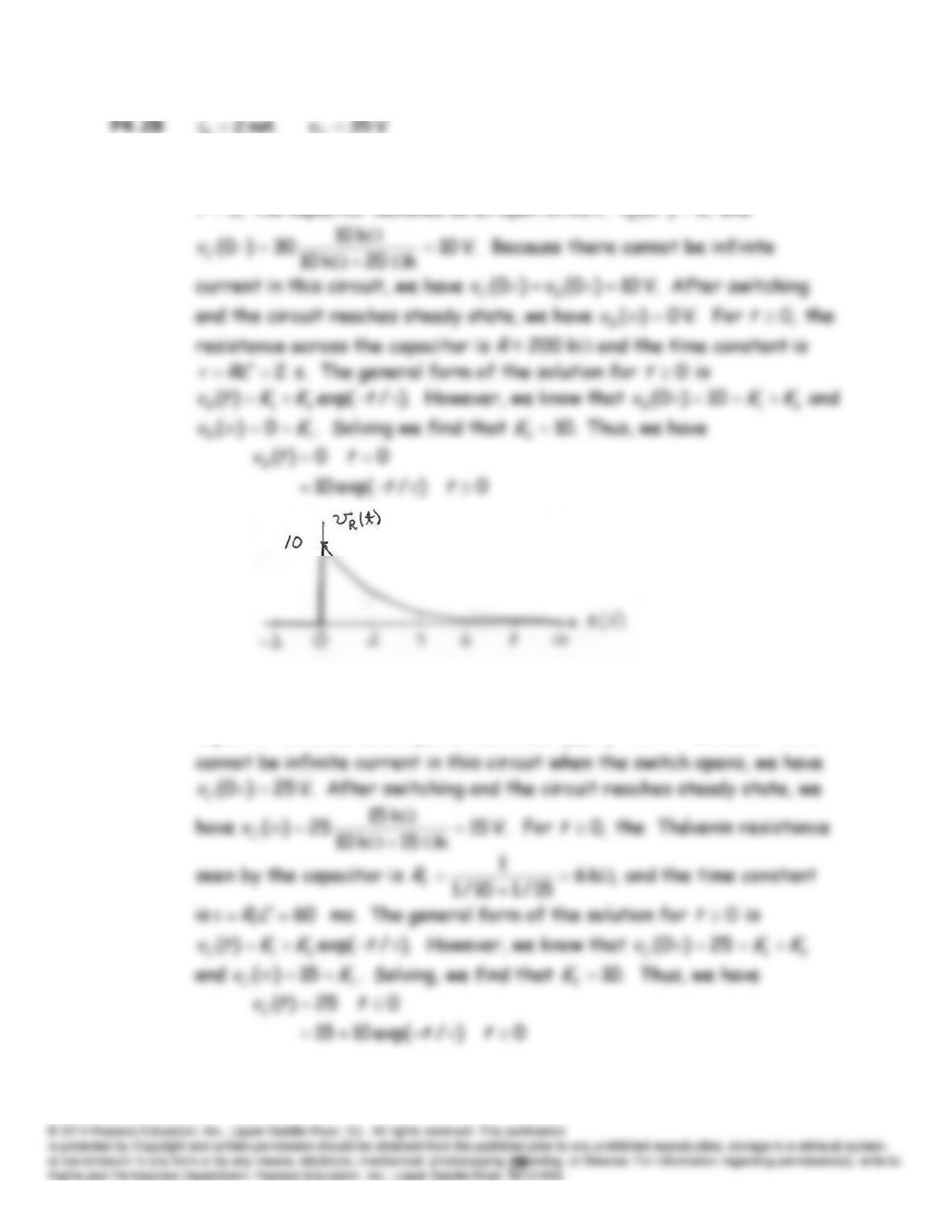
P4.27 With the circuit in steady state prior to
,0
t
the capacitor behaves as
an open circuit; the current is zero, and
50)0(
C
v
V. Because there
50)0(
C
v
A sketch of the capacitor voltage is:
R
C
P4.29* With the switch in position
A
and the circuit in steady state prior to
,0
t
t
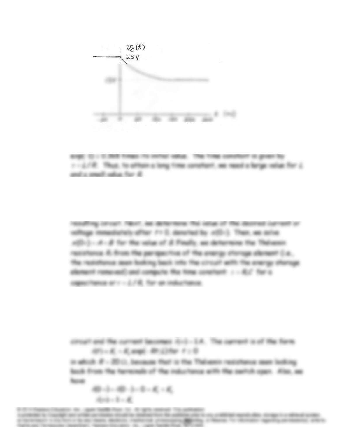
P4.30 With the switch closed and the circuit in steady state prior to
,0
t
the
capacitor behaves as an open circuit, and
V. 25)0(
v
Because there
P4.31 The time constant
is the interval required for the current to fall to
P4.32 The general form of the solution is
)/exp()(
tBAtx
.
A
is the
steady-state solution for
.0
t
To determine the value of
A
, we replace
the inductor with a short or the capacitance with an open and solve the
P4.33* In steady state with the switch closed, we have
0 for 0
tti
because the closed switch shorts the source.
In steady state with the switch open, the inductance acts as a short
1