Simple Resistive Circuits
Assessment Problems
AP 3.1
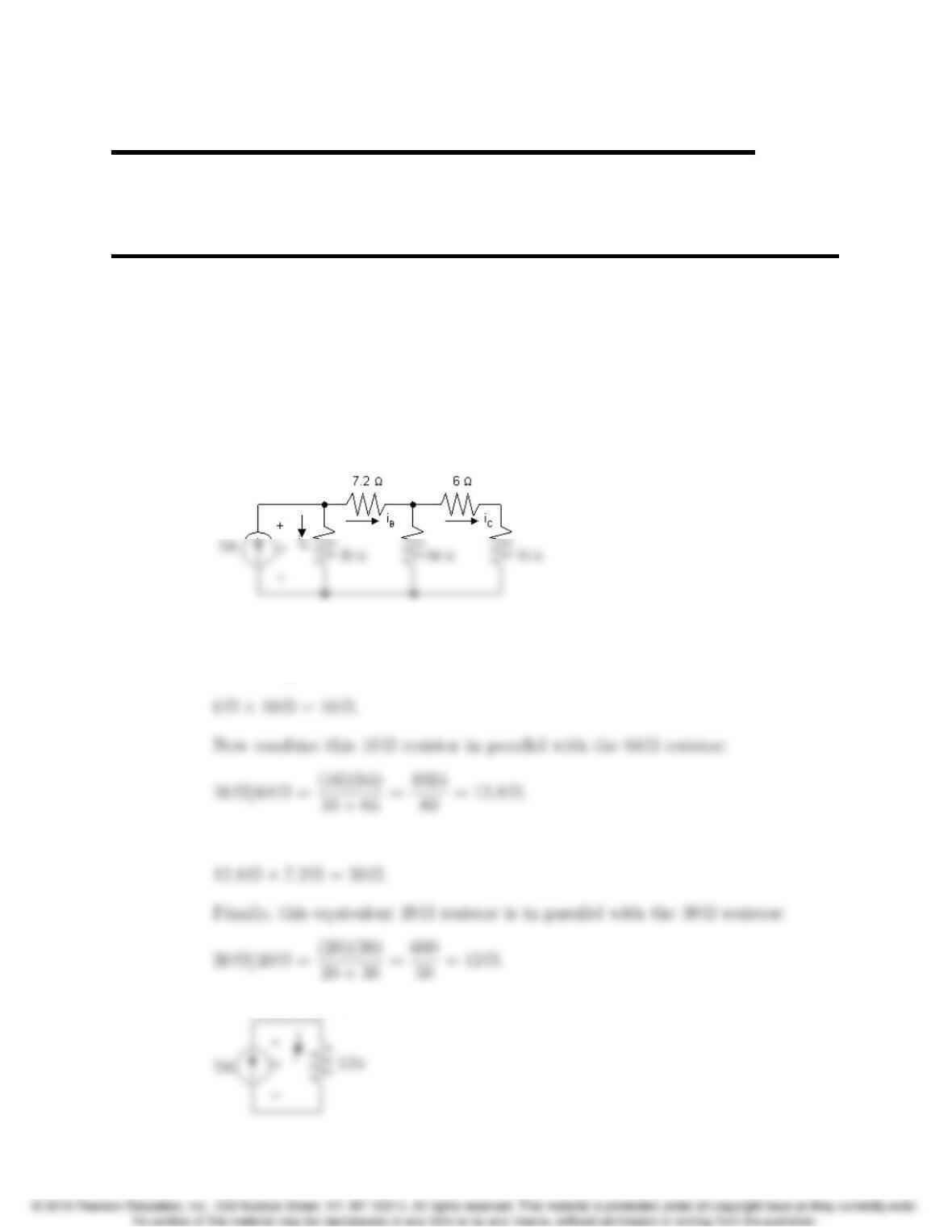
Start from the right hand side of the circuit and make series and parallel
combinations of the resistors until one equivalent resistor remains. Begin by
combining the 6 Ωresistor and the 10 Ωresistor in series:
This equivalent 12.8Ωresistor is in series with the 7.2Ωresistor:
Thus, the simplified circuit is as shown:
3–1
3
3–2 CHAPTER 3. Simple Resistive Circuits
[a] With the simplified circuit we can use Ohm’s law to find the voltage across
[b] Now that we know the value of the voltage drop across the current source,
we can use the formula p=vi to find the power associated with the
source:
[c] We now can return to the original circuit, shown in the first figure. In this
circuit, v= 60 V, as calculated in part (a). This is also the voltage drop
Now write a KCL equation at the upper left node to find the current iB:
Now that we have the current through the 10 Ωresistor we can use the
formula p=Ri2to find the power:
Problems 3–3
AP 3.2
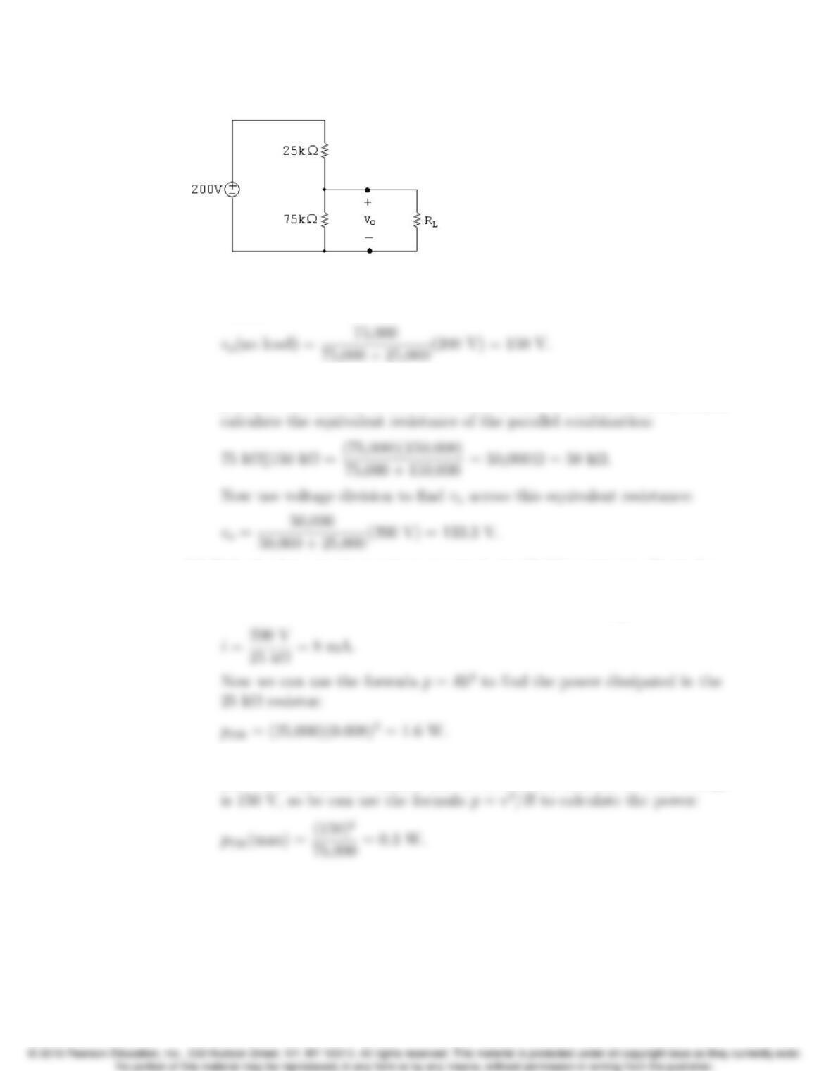
[a] We can use voltage division to calculate the voltage voacross the 75 kΩ
resistor:
[b] When we have a load resistance of 150 kΩthen the voltage vois across the
parallel combination of the 75 kΩresistor and the 150 kΩresistor. First,
[c] If the load terminals are short-circuited, the 75 kΩresistor is effectively
removed from the circuit, leaving only the voltage source and the 25 kΩ
resistor. We can calculate the current in the resistor using Ohm’s law:
[d] The power dissipated in the 75 kΩresistor will be maximum at no load
since vois maximum. In part (a) we determined that the no-load voltage
AP 3.3
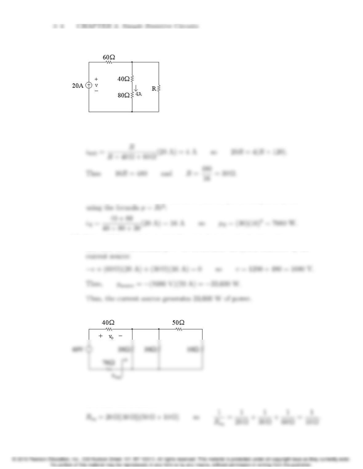
[a] We will write a current division equation for the current through the 80Ω
resistor and use this equation to solve for R:
[b] With R= 30 Ωwe can calculate the current through R using current
division, and then use this current to find the power dissipated by R,
[c] Write a KVL equation around the outer loop to solve for the voltage v,
and then use the formula p=vi to calculate the power delivered by the
AP 3.4
[a] First we need to determine the equivalent resistance to the right of the
40 Ωand 70 Ωresistors:
Problems 3–5
[b] The current through the 40 Ωresistor can be found using Ohm’s law:
This current flows from left to right through the 40 Ωresistor. To use
current division, we need to find the equivalent resistance of the two
parallel branches containing the 20 Ωresistor and the 50 Ωand 10 Ω
resistors:
[c] We can find the power dissipated by the 50 Ωresistor if we can find the
current in this resistor. We can use current division to find this current
from the current in the 40 Ωresistor, but first we need to calculate the
equivalent resistance of the 20 Ωbranch and the 30 Ωbranch:
AP 3.5 [a]
3–6 CHAPTER 3. Simple Resistive Circuits
[b]
AP 3.6 [a]
[b]
The meter resistance is a series combination of resistances:
Problems 3–7
AP 3.7 [a] Using the condition for a balanced bridge, the products of the opposite
resistors must be equal. Therefore,
[b] When the bridge is balanced, there is no current flowing through the
meter, so the meter acts like an open circuit. This places the following
branches in parallel: The branch with the voltage source, the branch with
the series combination R1and R3and the branch with the series
combination of R2and Rx. We can find the current in the latter two
branches using Ohm’s law:
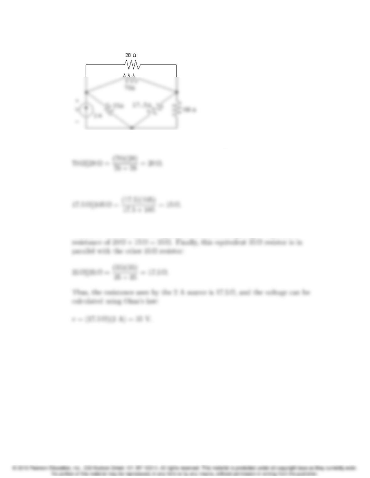
AP 3.8 Convert the three Y-connected resistors, 20 Ω, 10 Ω, and 5 Ωto three
∆-connected resistors Ra,R
b, and Rc. To assist you the figure below has both
the Y-connected resistors and the ∆-connected resistors
3–8 CHAPTER 3. Simple Resistive Circuits
The circuit with these new ∆-connected resistors is shown below:
From this circuit we see that the 70 Ωresistor is parallel to the 28 Ωresistor:
Also, the 17.5Ωresistor is parallel to the 105 Ωresistor:
Once the parallel combinations are made, we can see that the equivalent 20 Ω
resistor is in series with the equivalent 15 Ωresistor, giving an equivalent
Problems 3–9
Problems
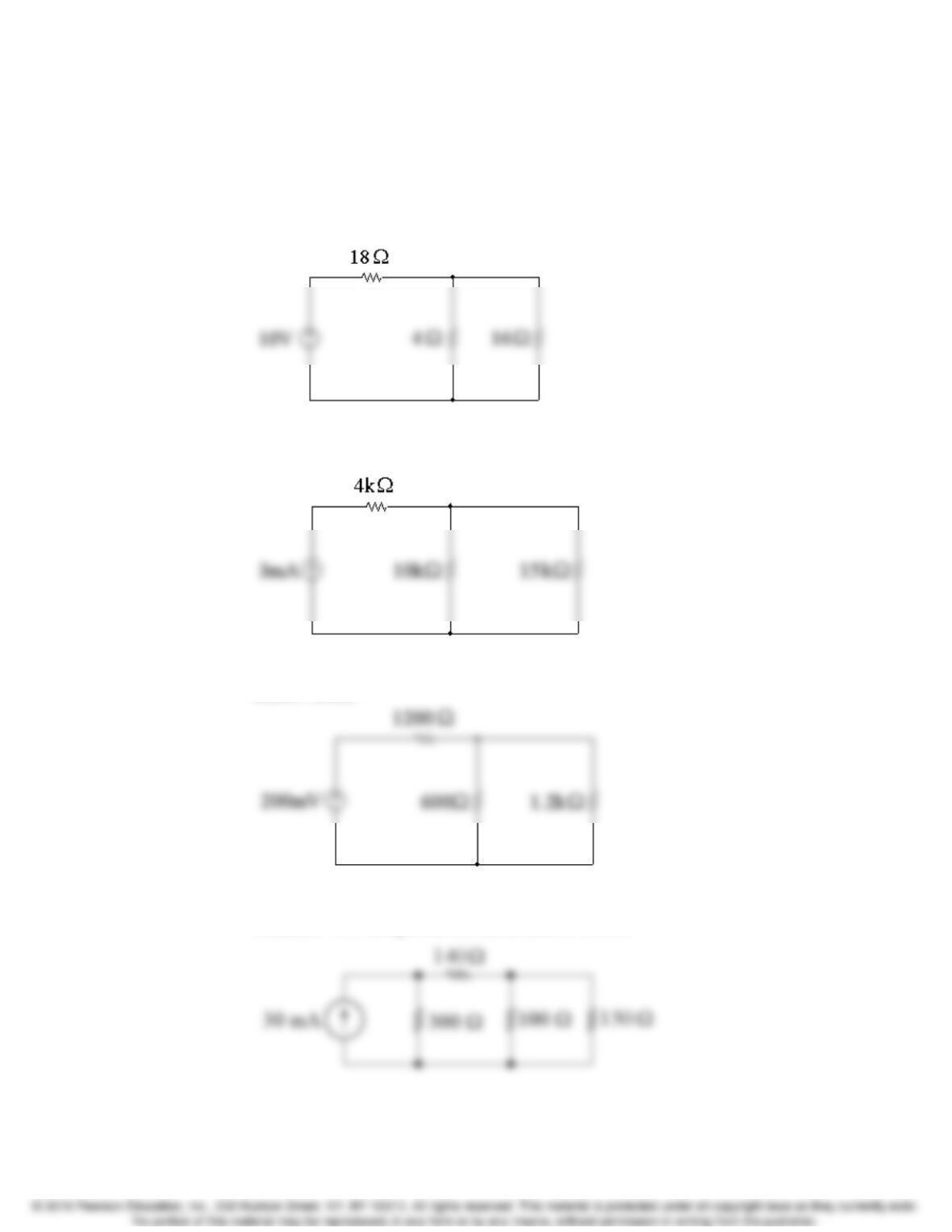
P 3.1 [a] The 6 Ωand 12 Ωresistors are in series, as are the 9 Ωand 7 Ωresistors.
The simplified circuit is shown below:
[b] The 3 kΩ, 5 kΩ, and 7 kΩresistors are in series. The simplified circuit is
shown below:
[c] The 300 Ω, 400 Ω, and 500 Ωresistors are in series. The simplified circuit is
shown below:
[d] The 50 Ωand 90 Ωresistors are in series, as are the 80 Ωand 70 Ω
resistors. The simplified circuit is shown below:
P 3.2 Always work from the side of the circuit furthest from the source. Remember
that the current in all series-connected circuits is the same, and that the
voltage drop across all parallel-connected resistors is the same.
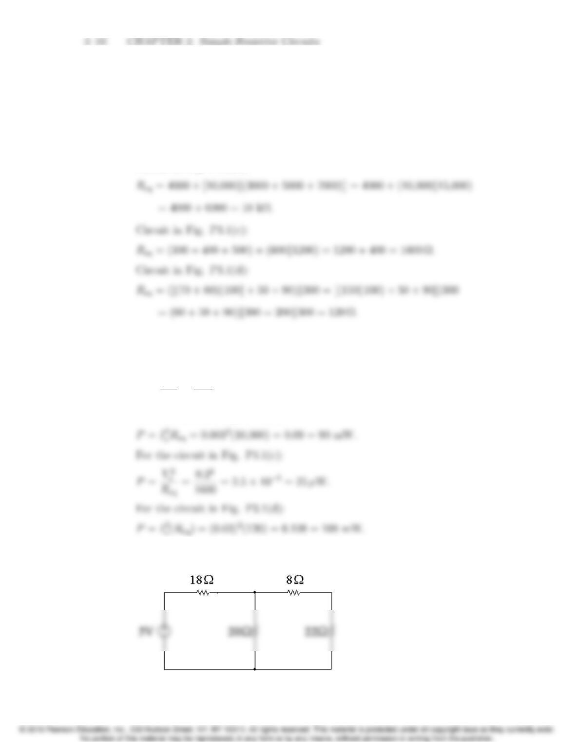
[a] Circuit in Fig. P3.1(a):
Req = 6 + 12 + [4k(9 + 7)] = 18 + (4k16) = 18 + 3.2=21.2Ω.
Circuit in Fig. P3.1(b):
[b] Note that in every case, the power delivered by the source must equal the
power absorbed by the equivalent resistance in the circuit. For the circuit
in Fig. P3.1(a):
P=V2
s
Req
=102
21.2=4.717 W.
For the circuit in Fig. P3.1(b):
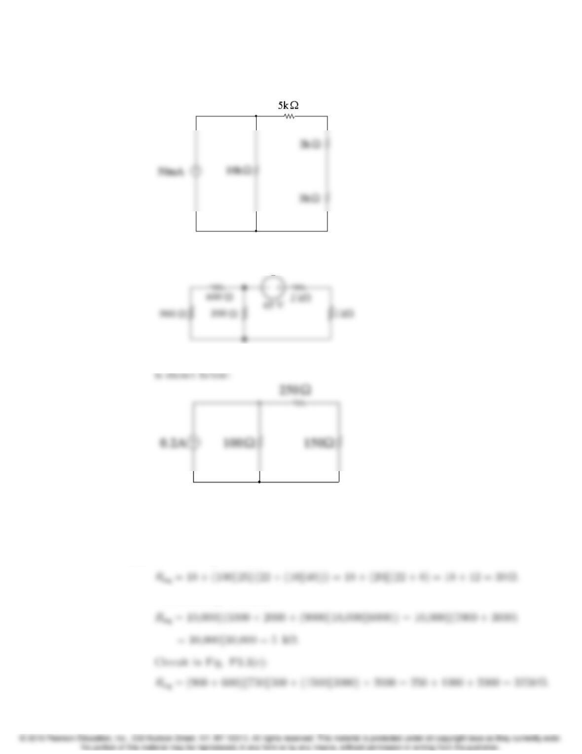
P 3.3 [a] The 10 Ωand 40 Ωresistors are in parallel, as are the 100 Ωand 25 Ω
resistors. The simplified circuit is shown below:
Problems 3–11
[b] The 9 kΩ, 18 kΩ, and 6 kΩresistors are in parallel. The simplified circuit
is shown below:
[c] The 750 Ωand 500 Ωresistors are in parallel, as are the 1.5 kΩand 3 kΩ
resistors. The simplified circuit is shown below:
[d] The 600 Ω, 200 Ω, and 300 Ωresistors are in series. The simplified circuit
P 3.4 Always work from the side of the circuit furthest from the source. Remember
that the current in all series-connected circuits is the same, and that the
voltage drop across all parallel-connected resistors is the same.
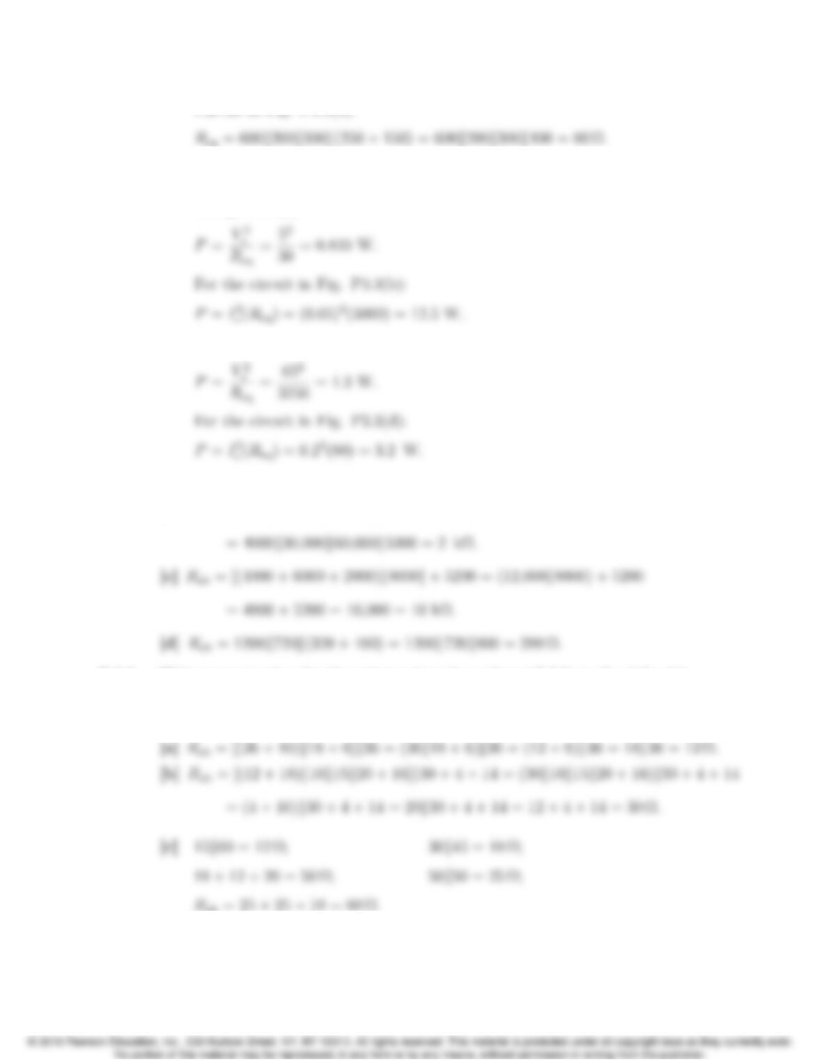
[a] Circuit in Fig. P3.3(a):
Circuit in Fig. P3.3(b):
3–12 CHAPTER 3. Simple Resistive Circuits
Circuit in Fig. P3.3(d):
[b] Note that in every case, the power delivered by the source must equal the
power absorbed by the equivalent resistance in the circuit. For the circuit
in Fig. P3.3(a):
For the circuit in Fig. P3.3(c):
P 3.5 [a] Rab = 12 + (24k(30 + 18)) + 10 = 12 + (24k48) + 10 = 12 + 16 + 10 = 38 Ω.
[b] Rab = 4000k30,000k60,000k(1200 + (7200k2400) + 2000)
P 3.6 Write an expression for the resistors in series and parallel from the right side
of the circuit to the left. Then simplify the resulting expression from left to
right to find the equivalent resistance.
Problems 3–13
[d] 18 + 12 = 30 Ω; 30k60 = 20 Ω;
P 3.7 [a] Circuit in Fig. P3.7(a):
Req = 360k(90 + 120k(160 + 200)) = 360k(90 + (120k360)) = 360k(90 + 90)
Circuit in Fig. P3.7(b):
Req = ([(750 + 250)k1000] + 100)k([(150 + 600)k500] + 300)
Circuit in Fig. P3.7(c):
1
Re
=1
20 +1
15 +1
20 +1
4+1
12 =30
60 =1
2;
3–14 CHAPTER 3. Simple Resistive Circuits
[b] Note that in every case, the power delivered by the source must equal the
power absorbed by the equivalent resistance in the circuit. For the circuit
in Fig. P3.7(a):
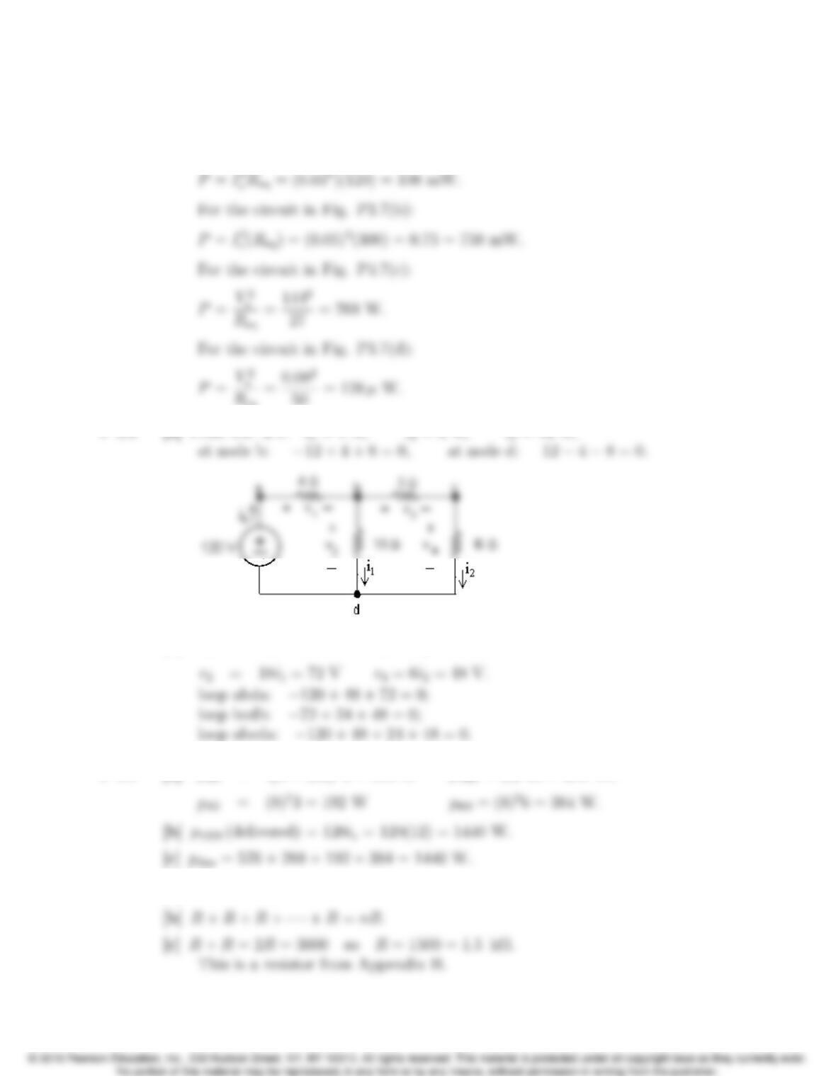
[b] v1=4is= 48 V v3=3i2= 24 V;
P 3.9 [a] p4Ω=i2
P 3.10 [a] R+R=2R.
Problems 3–15
P 3.11 [a] Req =RkR=R2
2R=R
2.
[b] Req =RkRkRk···kR(nR’s)
[d] R
P 3.12 4 = 20R2
R2+40 so R2= 10 Ω;
P 3.13 [a] vo=500
(500 + 2000)(75) = 15 V.
[b] i= 75/2500 = 30 mA;
[c] Since R1and R2carry the same current and R1>R
2to satisfy the voltage
requirement, first pick R1to meet the 1 W specification
P 3.14 [a] vo=40R2
R1+R2
=8 so R1=4R2.
[b] The resistor that must dissipate the most power is R1, as it has the largest
resistance and carries the same current as the parallel combination of R2
P 3.15 Refer to the solution to Problem 3.14. The voltage divider will reach the
maximum power it can safely dissipate when the power dissipated in R1equals
1 W. Thus,
v2
R1
1200 =1 so vR1= 34.64 V.
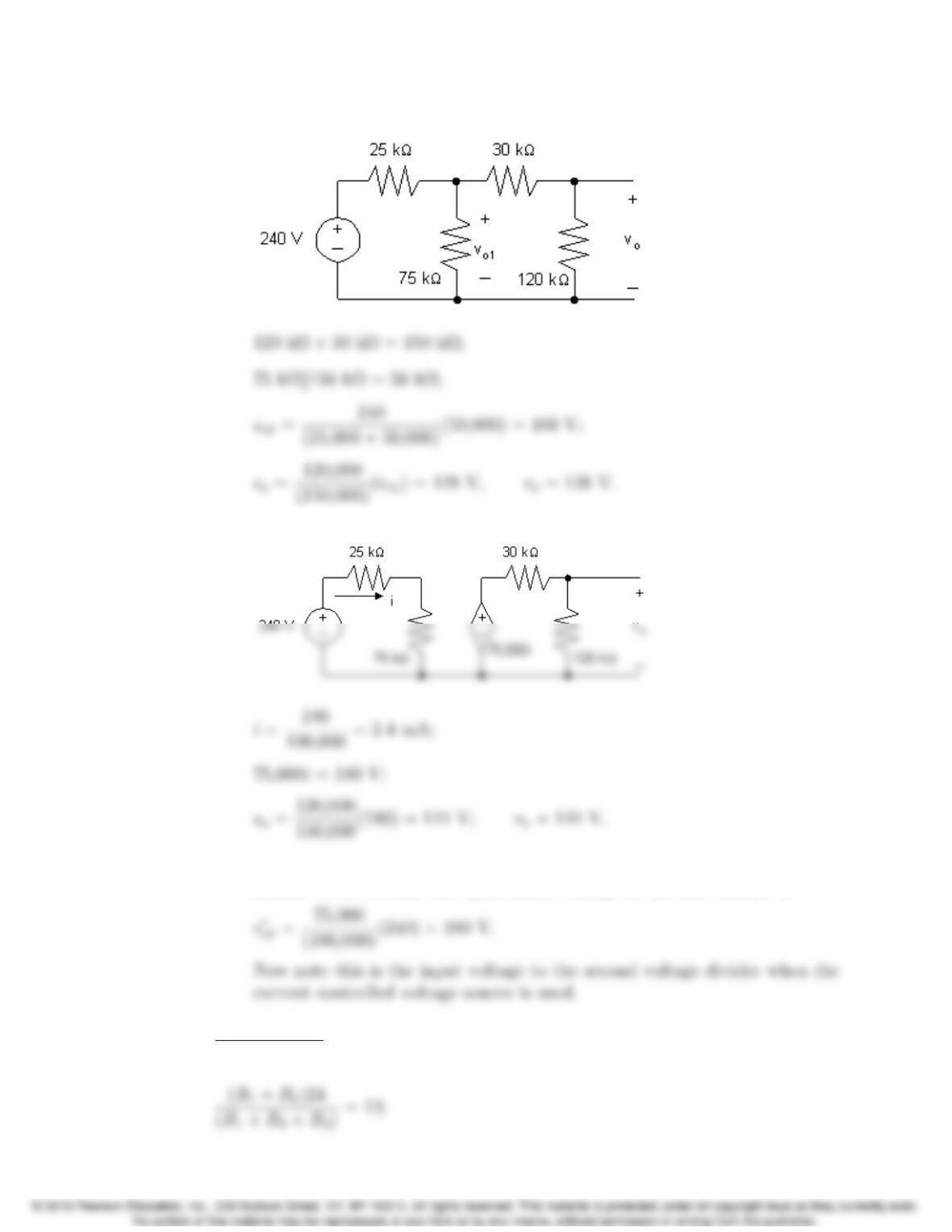
Problems 3–17
P 3.16 [a ]
[b ]
[c] It removes loading effect of second voltage divider on the first voltage
divider. Observe that the open circuit voltage of the first divider is
P 3.17 (24)2
R1+R2+R3
= 80,Therefore, R1+R2+R3=7.2Ω.
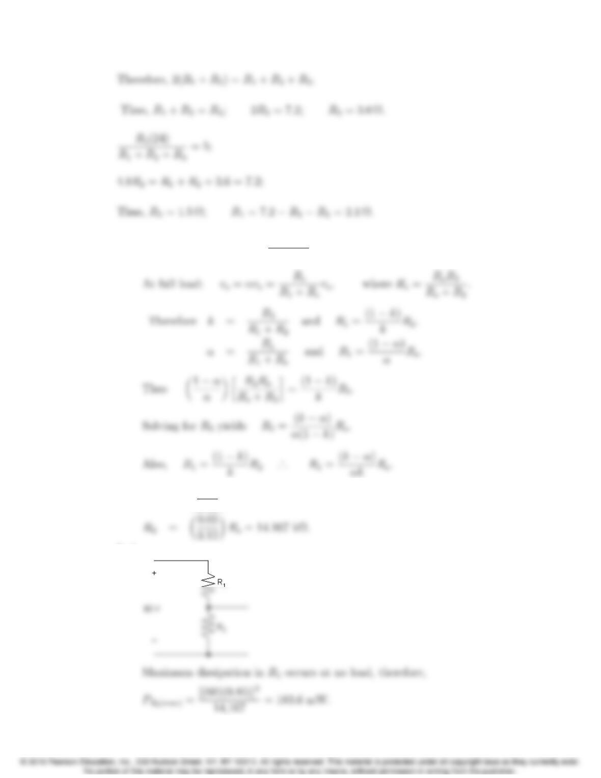
3–18 CHAPTER 3. Simple Resistive Circuits
P 3.18 [a] At no load: vo=kvs=R2
R1+R2
vs.
[b] R1=✓0.05
0.68◆Ro=2.5 kΩ;
[c ]
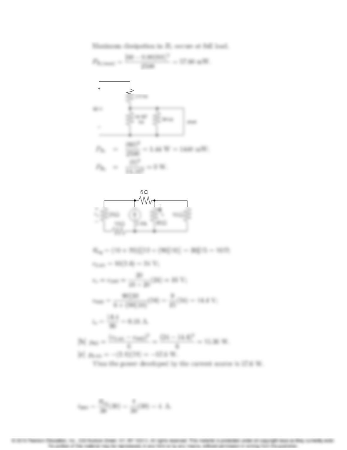
Problems 3–19
[d ]
P 3.19 [a]
P 3.20 Req =6k30k20 = 4 Ω.
Using current division, the current in the 30 Ωresistor is
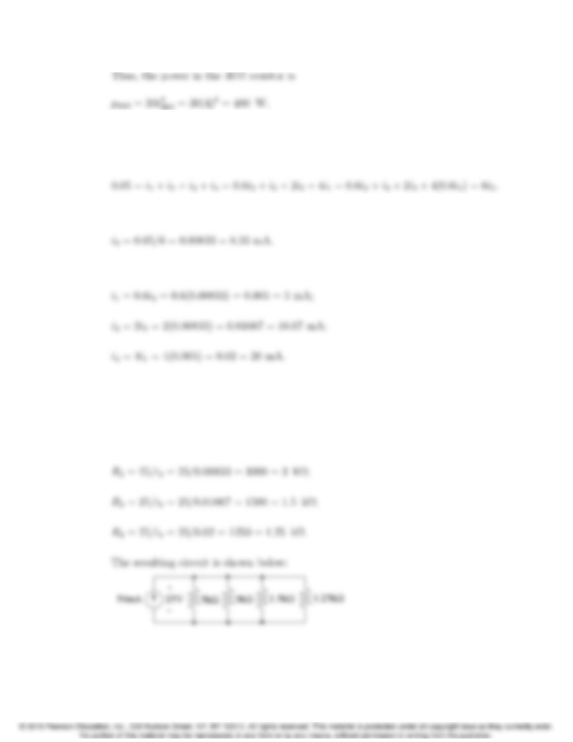
3–20 CHAPTER 3. Simple Resistive Circuits
P 3.21 Begin by using KCL at the top node to relate the branch currents to the
current supplied by the source. Then use the relationships among the branch
currents to express every term in the KCL equation using just i2:
Therefore,
Find the remaining currents using the value of i2:
Since the resistors are in parallel, the same voltage, 25 V, appears across each
of them. We know the current and the voltage for every resistor so we can use
Ohm’s law to calculate the values of the resistors:
R1= 25/i1= 25/0.005 = 5000 = 5 kΩ;