Problems 3–21
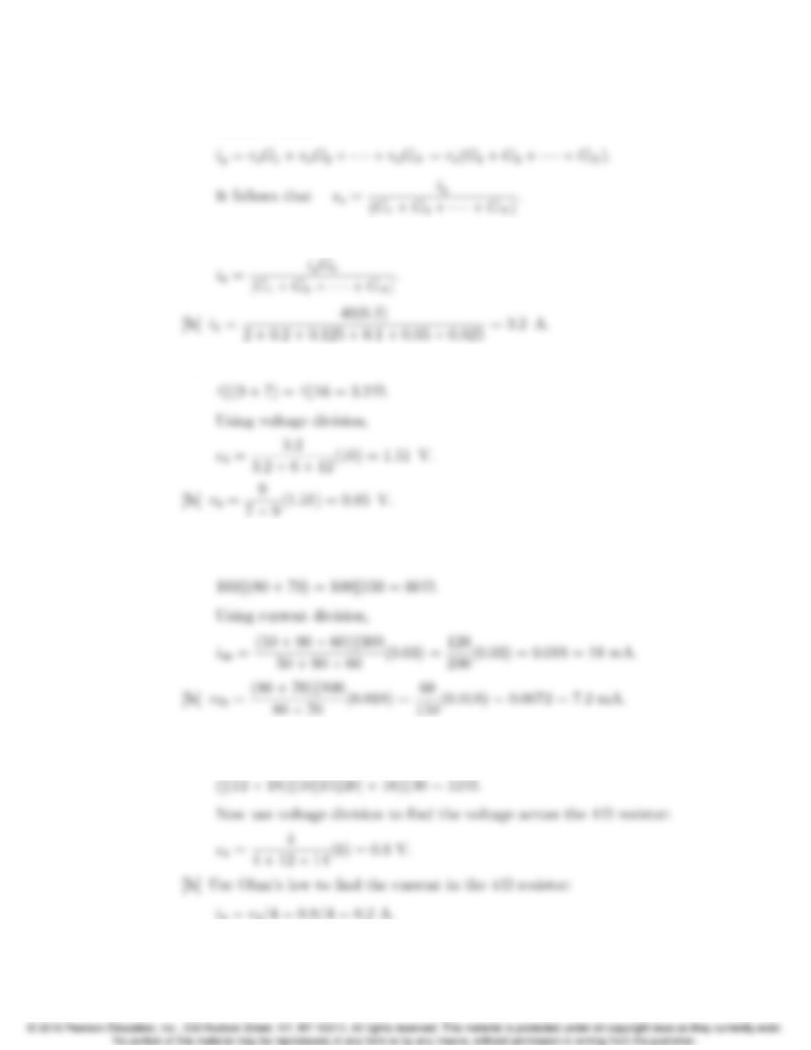
P 3.22 [a] Let vobe the voltage across the parallel branches, positive at the upper
terminal, then
The current in the kth branch is ik=voGk; Thus,
P 3.23 [a] The equivalent resistance of the 4 Ωresistor and the resistors to its right is
P 3.24 [a] The equivalent resistance of the 100 Ωresistor and the resistors to its right
is
P 3.25 [a] Begin by finding the equivalent resistance of the 30 Ωresistor and all
resistors to its right:
3–22 CHAPTER 3. Simple Resistive Circuits
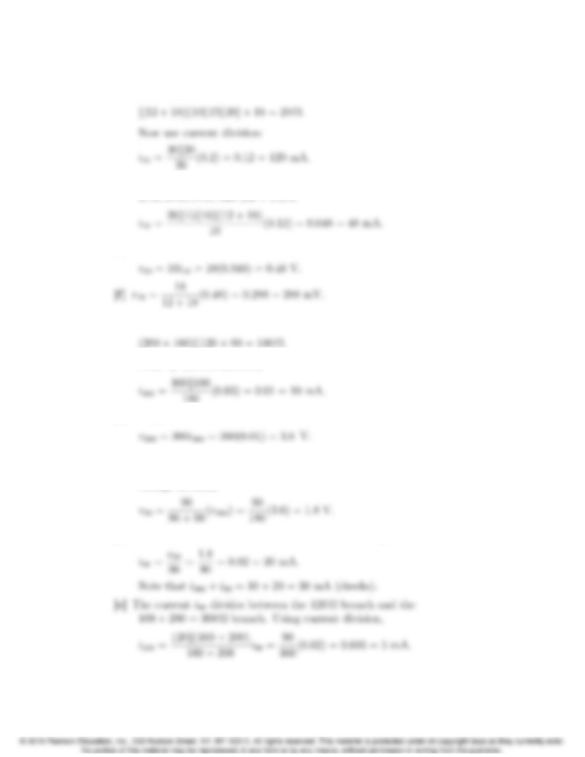
[c] Begin by finding the equivalent resistance of all resistors to the right of the
30 Ωresistor:
[d] Note that the current in the 16 Ωresistor divides among four branches –
20 Ω,15 Ω,10 Ω, and (12 + 18) Ω:
[e] Use Ohm’s law to find the voltage across the 10 Ωresistor:
P 3.26 [a] The equivalent resistance of the circuit to the right of the 360 Ωresistor is
Thus by current division,
[b] Using Ohm’s law:
[c] The voltage across the 360 Ωresistor divides between two resistors – the
90 Ωresistor and the 120k(160 + 200) = 90 Ωequivalent resistance. Using
voltage division,
[d] The current in the 90 Ωresistor can be found using Ohm’s law:
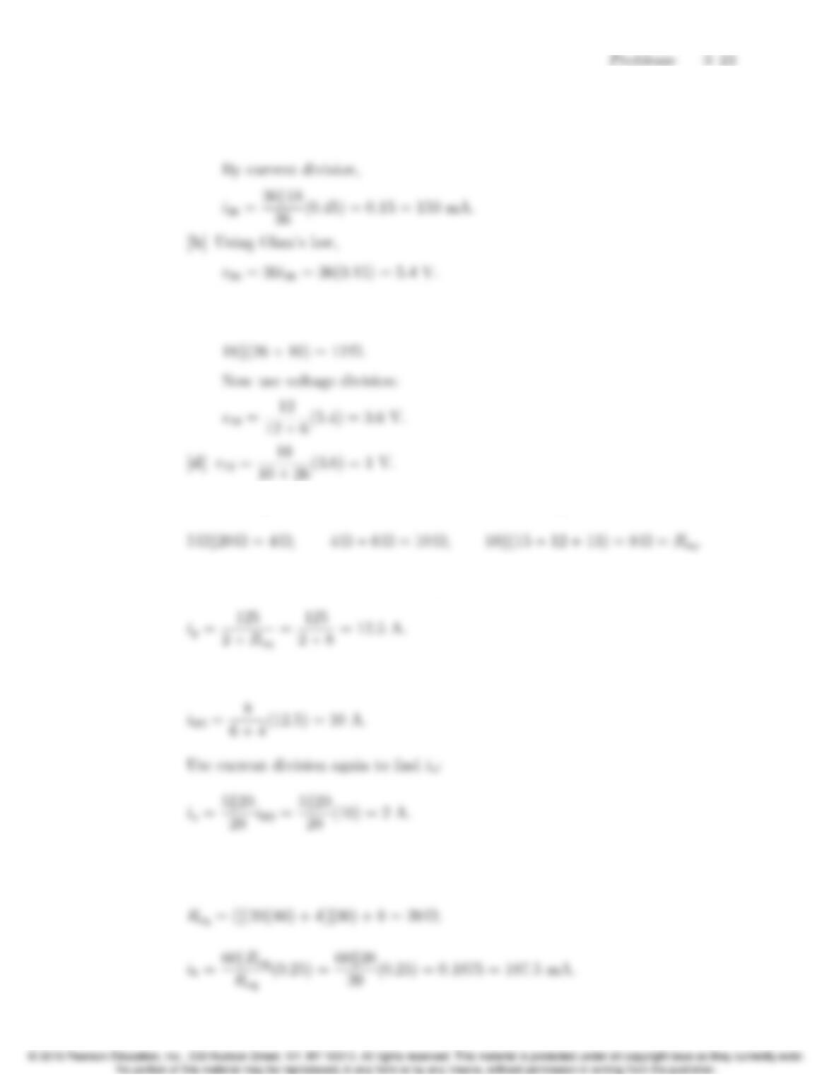
P 3.27 [a] The equivalent resistance to the right of the 36 Ωresistor is
6 + [18k(26 + 10)] = 18 Ω.
[c] Before using voltage division, find the equivalent resistance of the 18 Ω
resistor and the resistors to its right:
P 3.28 Find the equivalent resistance of all the resistors except the 2 Ω:
Use Ohm’s law to find the current ig:
Use current division to find the current in the 6 Ωresistor:
P 3.29 Use current division to find the current in the 8 Ωresistor. Begin by finding
the equivalent resistance of the 8 Ωresistor and all resistors to its right:
3–24 CHAPTER 3. Simple Resistive Circuits
Use current division to find i1from i8:
Use current division to find i4Ωfrom i8:
Finally, use current division to find i2from i4Ω:
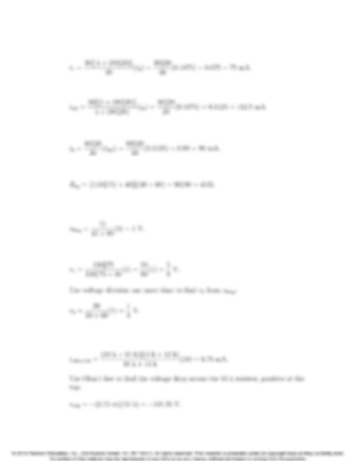
P 3.30 The equivalent resistance of the circuit to the right of the 90 Ωresistor is
Use voltage division to find the voltage drop between the top and bottom
nodes:
Use voltage division again to find v1from vReq:
P 3.31 Use current division to find the current in the branch containing the 10 k and
15 k resistors, from bottom to top
Problems 3–25
Find the current in the branch containing the 3 k and 12 k resistors, from
bottom to top
P 3.32 [a] v20k =20
20 + 5(45) = 36 V;
[b] v20k =20
25(Vs)=0.8vs;
P 3.33
3–26 CHAPTER 3. Simple Resistive Circuits
P 3.34 [a] The model of the ammeter is an ideal ammeter in parallel with a resistor
whose resistance is given by
[b] At full scale, imeas = 1 A or 106µA, and im= 10 µA so 999,990 µA flows
throught the resistor RA:
P 3.35 The current in the shunt resistor at full-scale deflection is
iA=ifullscale 3⇥10−3A. The voltage across RAat full-scale deflection is
always 150 mV; therefore,
[b] Let Rmbe the equivalent ammeter resistance:
P 3.36 At full scale the voltage across the shunt resistor will be 100 mV; therefore the
power dissipated will be
Problems 3–27
Otherwise the power dissipated in RAwill exceed its power rating of 0.25 W.
P 3.37 For all full-scale readings the total resistance is
We can calculate the resistance of the movement as follows:
Therefore, Rv= 1000 (full-scale reading) 20.
P 3.38 [a] vmeas = (50 ⇥10−3)[15k45k(4980 + 20)] = 0.5612 V.
P 3.39 The current in the 10 Ωresistor is the voltage supplied divided by the
equivalent resistance attached to the voltage source:
The current measured by the ammeter is found using current division:
3–28 CHAPTER 3. Simple Resistive Circuits
so the true value of the current in the 20 Ωresistor is
P 3.40 Begin by using current division to find the actual value of the current io:
P 3.41 [a ]
[b] With the insertion of the ammeter the equations become
Problems 3–29
P 3.42 Rmeter =Rm+Rmovement =500 V
0.5 mA = 1000 kΩ;
P 3.43 [a] R1= (100/0.002) = 50 kΩ;
[b] Let ia= actual current in the movement;
For the 100 V scale:
ia=100
50,000 + 25 =100
50,025,i
d=100
50,000;
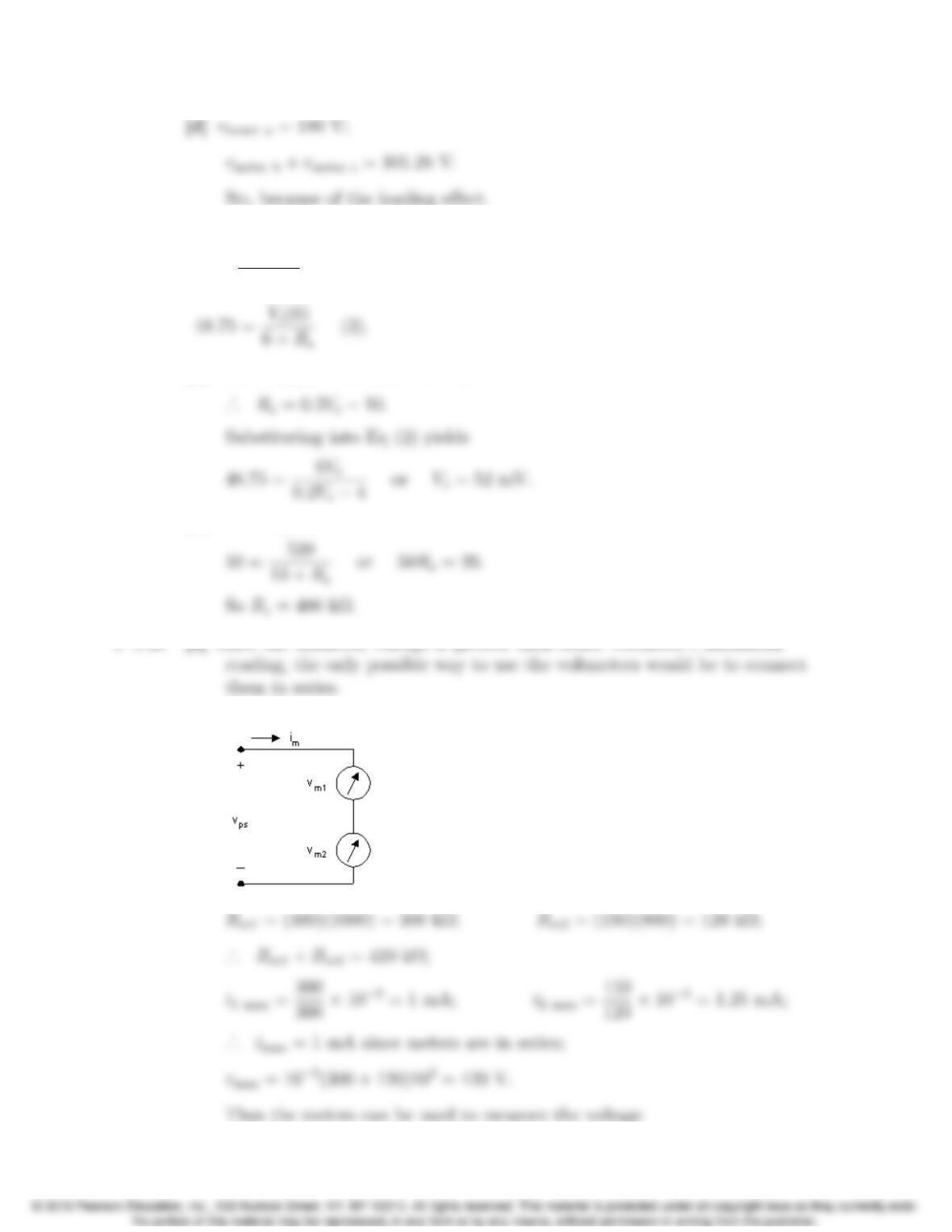
P 3.44 [a] vmeter = 180 V.
[b] Rmeter = (100)(200) = 20 kΩ;
3–30 CHAPTER 3. Simple Resistive Circuits
P 3.45 From the problem statement we have
50 = Vs(10)
10 + Rs
(1) Vsin mV; Rsin MΩ;
[a] From Eq (1) 10 + Rs=0.2Vs;
[b] From Eq (1)
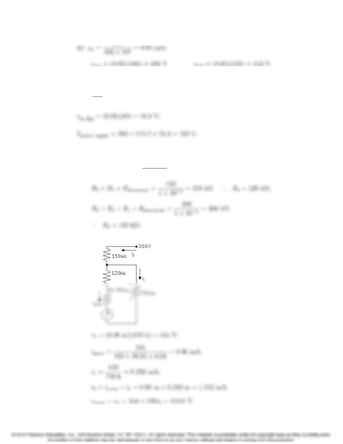
P 3.46 [a] Since the unknown voltage is greater than either voltmeter’s maximum
[b ]
Problems 3–31
P 3.47 The current in the series-connected voltmeters is
im=288
300 =0.96 mA;
P 3.48 [a] Rmovement = 50 Ω;
R1+Rmovement =30
1⇥10−3= 30 kΩ·
.. R
1= 29,950 Ω;
[b]
3–32 CHAPTER 3. Simple Resistive Circuits
P 3.49 [a] Rmeter = 360 kΩ+ 200 kΩk50 kΩ= 400 kΩ;
[b] What is the percent error in the measured voltage?
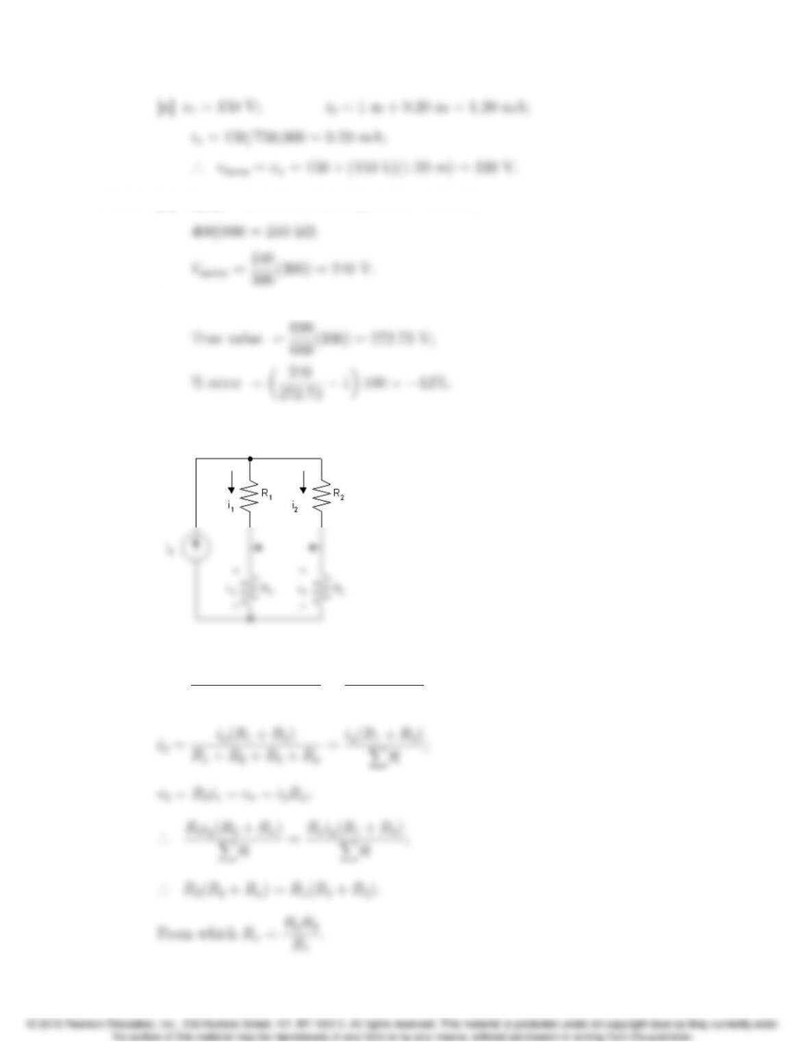
P 3.50 Since the bridge is balanced, we can remove the detector without disturbing
the voltages and currents in the circuit.
It follows that
i1=ig(R2+Rx)
R1+R2+R3+Rx
=ig(R2+Rx)
XR;
P 3.51 [a]
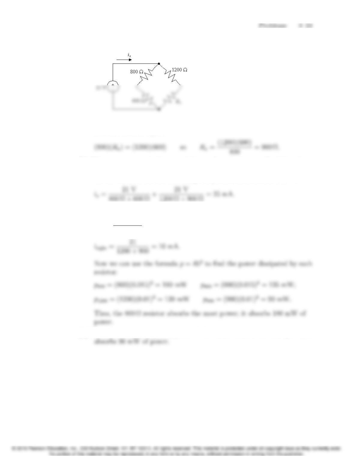
The condition for a balanced bridge is that the product of the opposite
resistors must be equal:
[b] The source current is the sum of the two branch currents. Each branch
current can be determined using Ohm’s law, since the resistors in each
branch are in series and the voltage drop across each branch is 21 V:
[c] We can use Ohm’s law to find the current in each branch:
ileft =21
800 + 600 = 15 mA;
[d] From the analysis in part (c), the 900 Ωresistor absorbs the least power; it
3–34 CHAPTER 3. Simple Resistive Circuits
P 3.52 Redraw the circuit, replacing the detector branch with a short circuit.
6 kΩk30 kΩ= 5 kΩ;
12 kΩk20 kΩ= 7.5 kΩ;
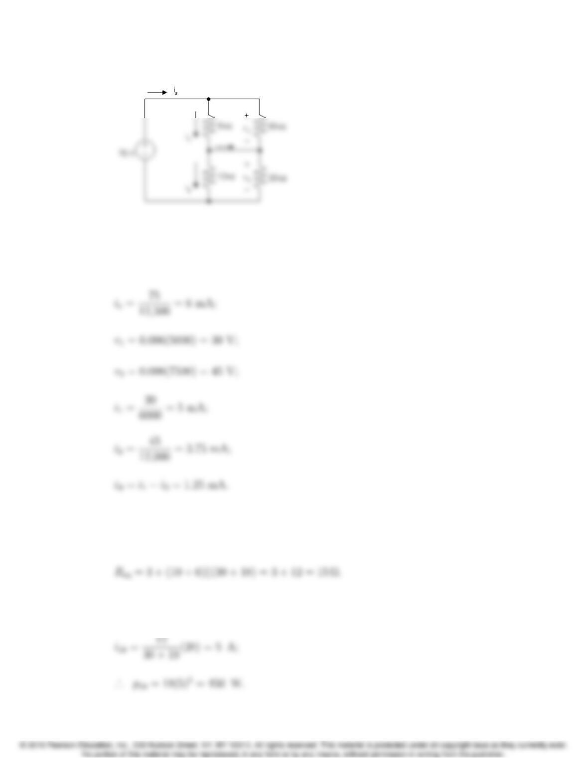
P 3.53 Note the bridge structure is balanced, that is 10 ⇥18 = 30 ⇥6, hence there is
no current in the 50Ωresistor. It follows that the equivalent resistance of the
circuit is
The source current is 300/15 = 20 A.
The current down through the branch containing the 30 Ωand 18 Ωresistors is
Problems 3–35
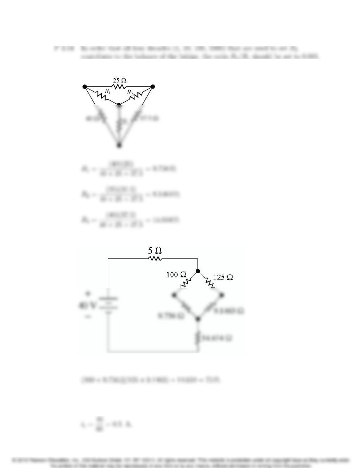
P 3.55 Use the figure below to transform the ∆to an equivalent Y:
Replace the ∆with its equivalent Y in the circuit to get the figure below:
Find the equivalent resistance to the right of the 5 Ωresistor:
The equivalent resistance seen by the source is thus 5 + 75 = 80 Ω. Use Ohm’s
law to find the current provided by the source:
3–36 CHAPTER 3. Simple Resistive Circuits
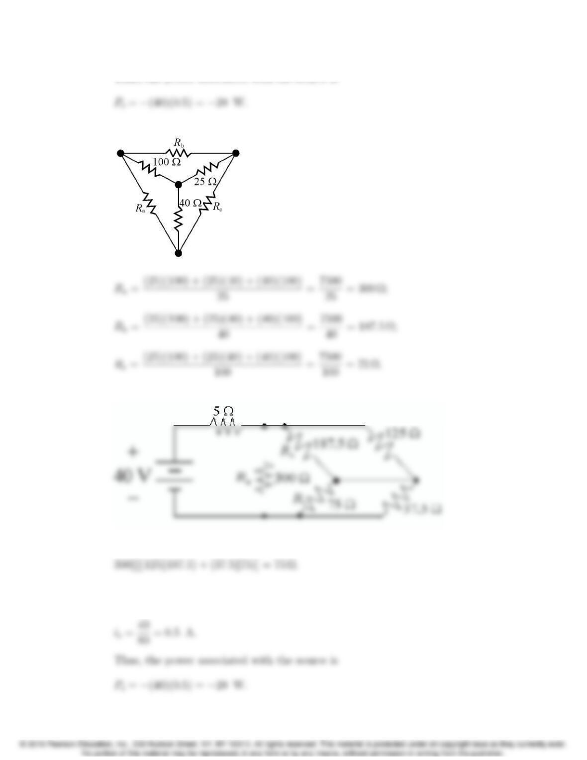
P 3.56 Use the figure below to transform the Y to an equivalent ∆:
Replace the Y with its equivalent ∆in the circuit to get the figure below:
Find the equivalent resistance to the right of the 5 Ωresistor:
The equivalent resistance seen by the source is thus 5 + 75 = 80 Ω. Use Ohm’s
law to find the current provided by the source: