Problems 3–37
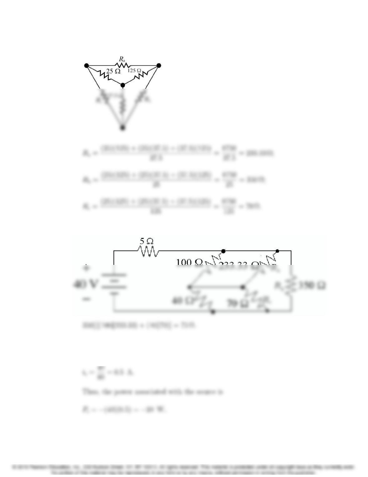
P 3.57 Use the figure below to transform the Y to an equivalent ∆:
Replace the Y with its equivalent ∆in the circuit to get the figure below:
The equivalent resistance seen by the source is thus 5 + 75 = 80 Ω. Use Ohm’s
law to find the current provided by the source:
3–38 CHAPTER 3. Simple Resistive Circuits
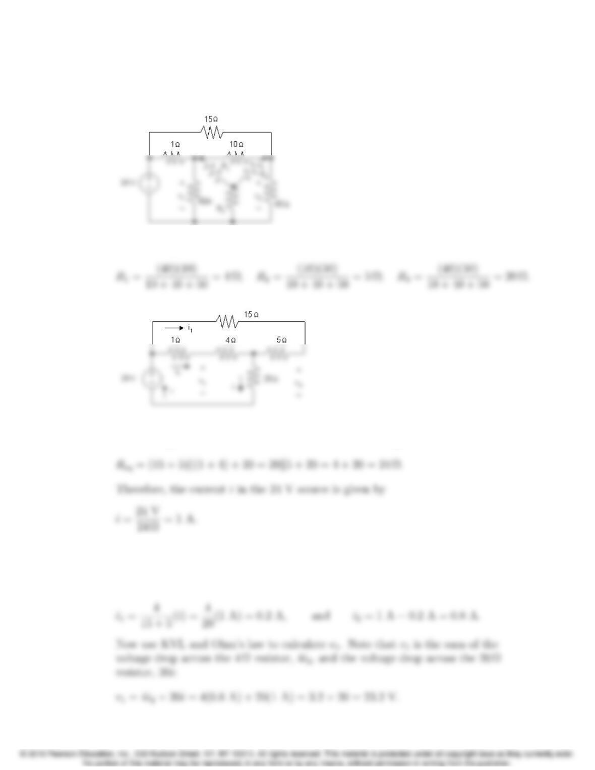
P 3.58 Begin by transforming the ∆-connected resistors (10 Ω,40 Ω,50 Ω) to
Y-connected resistors. Both the Y-connected and ∆-connected resistors are
shown below to assist in using Eqs. 3.15 – 3.17:
Now use Eqs. 3.15 – 3.17 to calculate the values of the Y-connected resistors:
The transformed circuit is shown below:
The equivalent resistance seen by the 24 V source can be calculated by making
series and parallel combinations of the resistors to the right of the 24 V source:
Use current division to calculate the currents i1and i2. Note that the current
i1flows in the branch containing the 15 Ωand 5 Ωseries connected resistors,
while the current i2flows in the parallel branch that contains the series
connection of the 1 Ωand 4 Ωresistors:
Problems 3–39
Finally, use KVL and Ohm’s law to calculate v2. Note that v2is the sum of
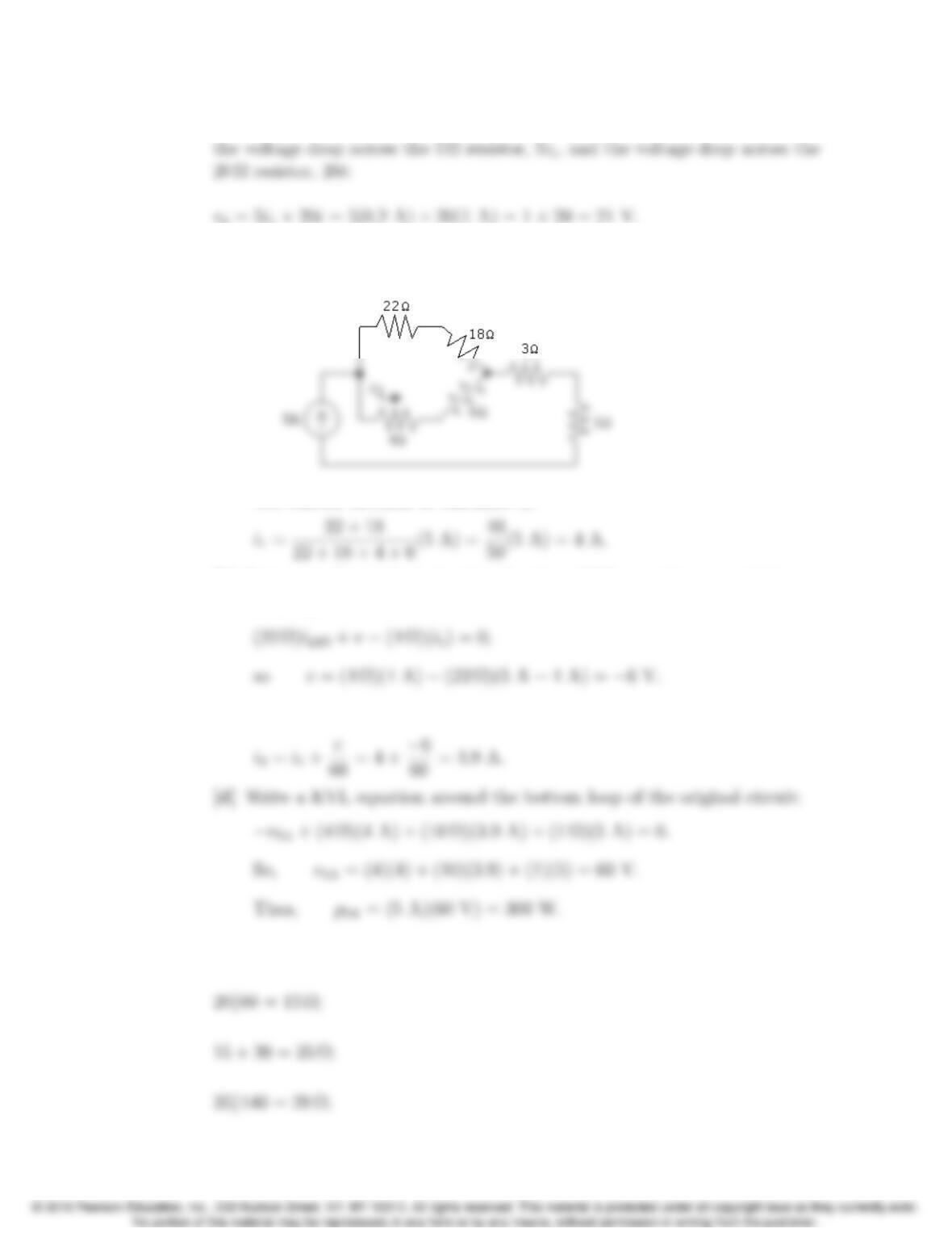
P 3.59 [a] After the 30 Ω—60 Ω—10 Ωdelta is replaced by its equivalent wye, the
circuit reduces to
Use current division to calculate i1:
[b] Return to the original circuit and write a KVL equation around the upper
left loop:
[c] Write a KCL equation at the lower center node of the original circuit:
P 3.60 8 + 12 = 20 Ω;
3–40 CHAPTER 3. Simple Resistive Circuits
28 + 22 = 50 Ω;
50k75 = 30 Ω;
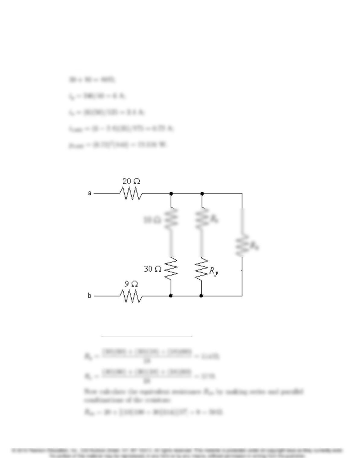
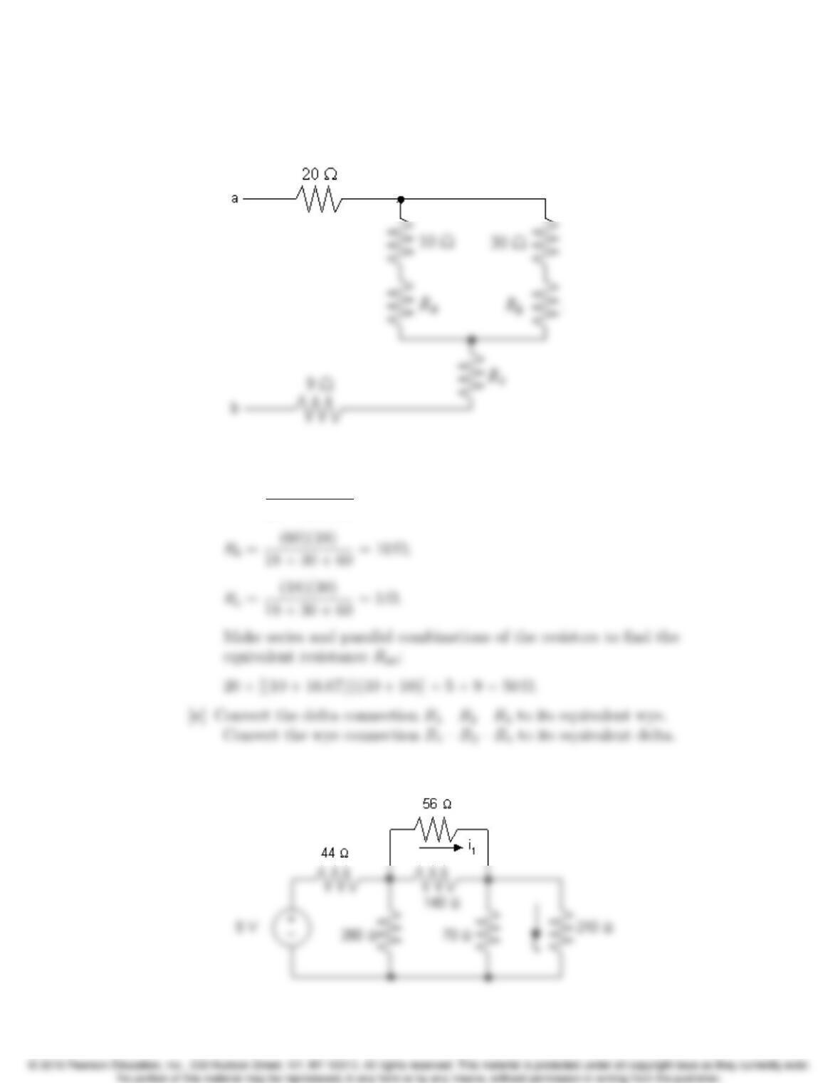
P 3.61 [a] The three Y-connected resistors, whose values are 30 Ω, 60 Ω, and 18 Ω,
have been replaced with three ∆-connected resistors in the figure below:
We calculate the values of the ∆-connected resistors using Eqs. 3.18–3.20:
Rx=(30)(60) + (30)(18) + (18)(60)
18 = 190 Ω;
Problems 3–41
[b] The three ∆-connected resistors, whose values are 30 Ω, 60 Ω, and 18 Ω,
have been replaced with three Y-connected resistors in the figure below:
We calculate the values of the Y-connected resistors using Eqs. 3.15–3.17:
Ra=(60)(30)
18 + 30 + 60 = 16.67 Ω;
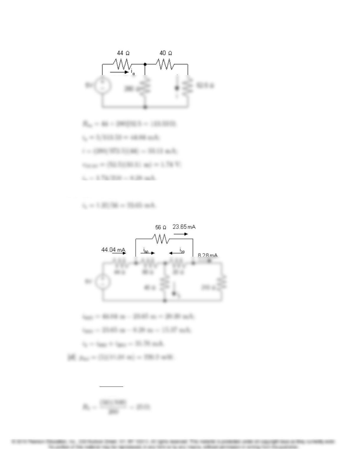
P 3.62 [a] After the 20 Ω—80 Ω—40 Ωwye is replaced by its equivalent delta, the
circuit reduces to
3–42 CHAPTER 3. Simple Resistive Circuits
Now the circuit can be reduced to
[b] v40Ω= (40)(33.11 m) = 1.32 V;
[c] Now that ioand i1are known return to the original circuit
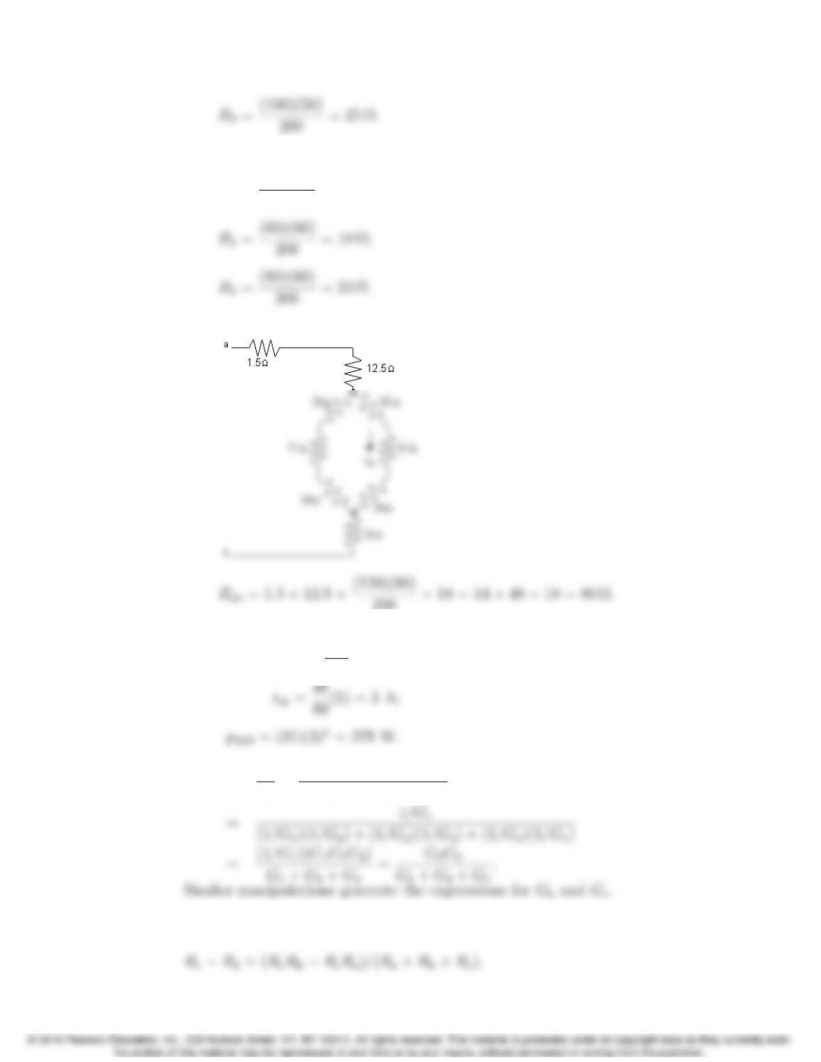
P 3.63 [a] Convert the upper delta to a wye.
R1=(50)(50)
200 = 12.5Ω;
Problems 3–43
Convert the lower delta to a wye.
R4=(60)(80)
200 = 24 Ω;
Now redraw the circuit using the wye equivalents.
200 + 18 = 14 + 48 + 18 = 80 Ω.
[b] When vab = 400 V,
ig=400
80 = 5 A;
P 3.64 Ga=1
Ra
=R1
R1R2+R2R3+R3R1
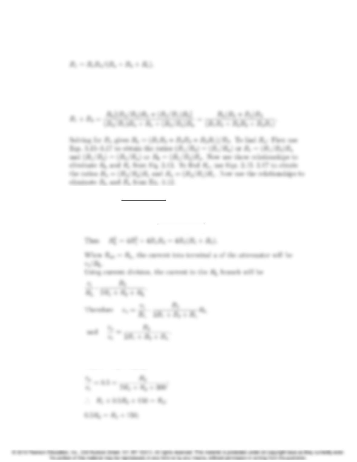
P 3.65 Subtracting Eq. 3.13 from Eq. 3.14 gives
3–44 CHAPTER 3. Simple Resistive Circuits
Adding this expression to Eq. 3.12 and solving for R1gives
To find R2, subtract Eq. 3.14 from Eq. 3.12 and add this result to Eq. 3.13.
To find R3, subtract Eq. 3.12 from Eq. 3.13 and add this result to Eq. 3.14.
Using the hint, Eq. 3.14 becomes
P 3.66 [a] Rab =2R1+R2(2R1+RL)
2R1+R2+RL
=RL.
Therefore 2R1RL+R2(2R1+RL)
2R1+R2+RL
=0.
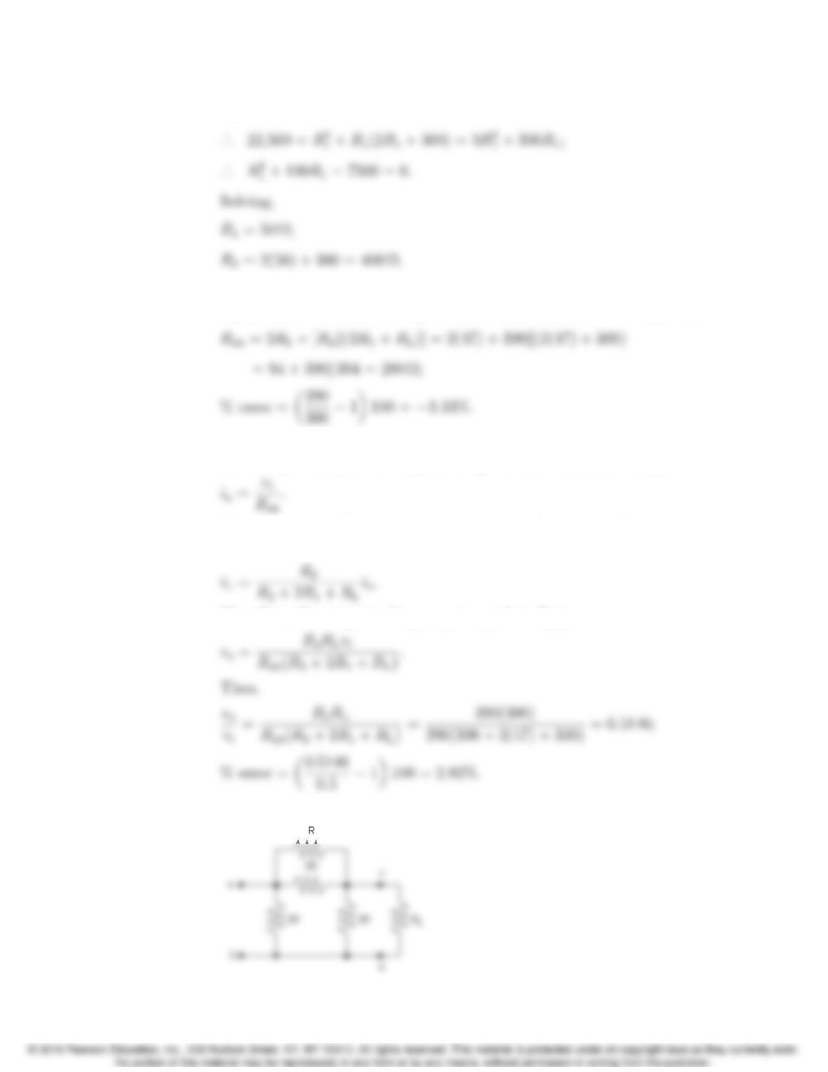
[b] (300)2= 4(R1+R2)R1;
22,500 = R2
1+R1R2;
Problems 3–45
R2=2R1+ 300;
[c] From Appendix H, choose R1= 47 Ωand R2= 390 Ω. For these values,
Rab 6=RL, so the equations given in part (a) cannot be used. Instead
Now calculate the ratio of the output voltage to the input voltage. Begin
by finding the current through the top left R1resistor, called ia:
Now use current division to find the current through the RLresistor,
called iL:
Therefore, the output voltage, vo, is equal to RLiL:
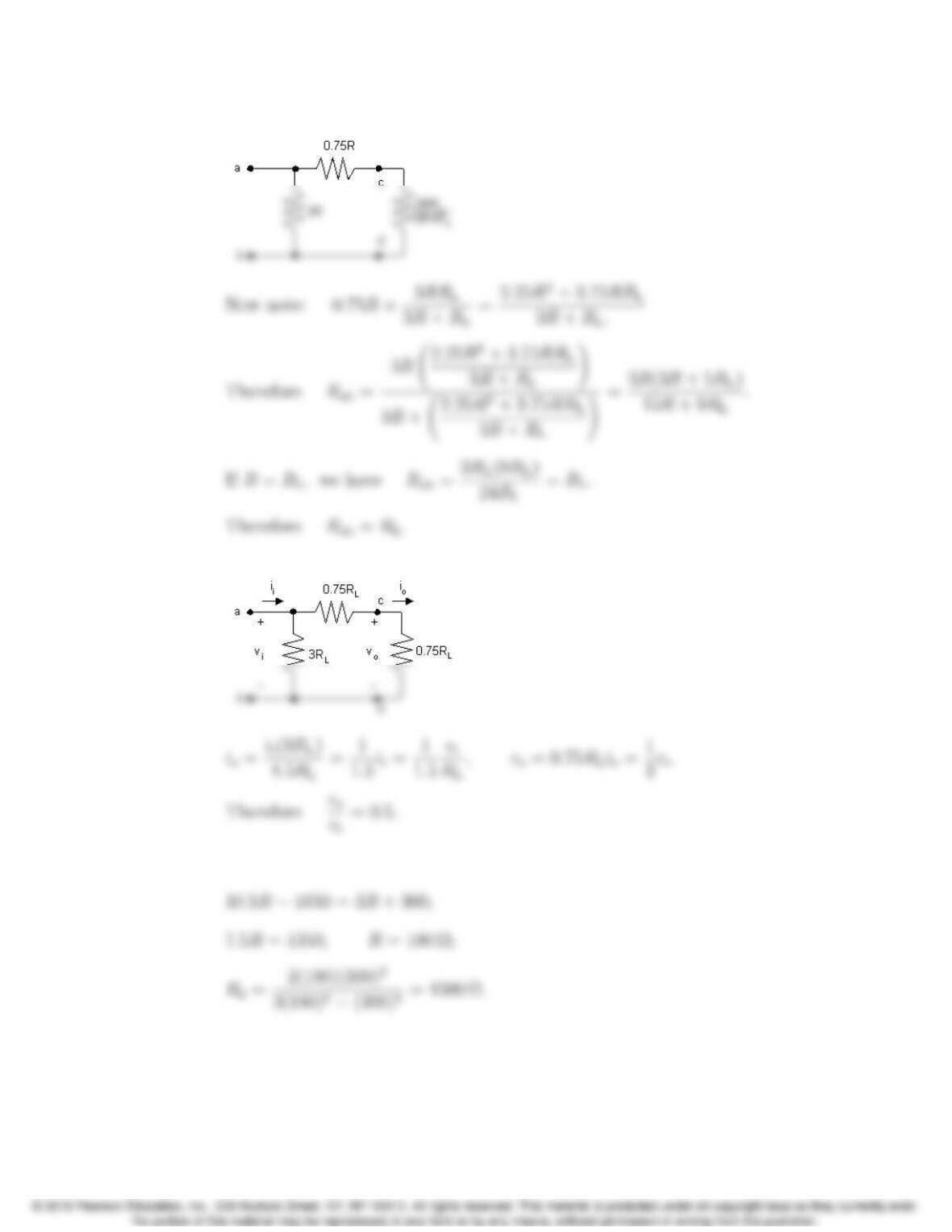
P 3.67 [a] After making the Y-to-∆transformation, the circuit reduces to
3–46 CHAPTER 3. Simple Resistive Circuits
Combining the parallel resistors reduces the circuit to
[b] When R=RL, the circuit reduces to
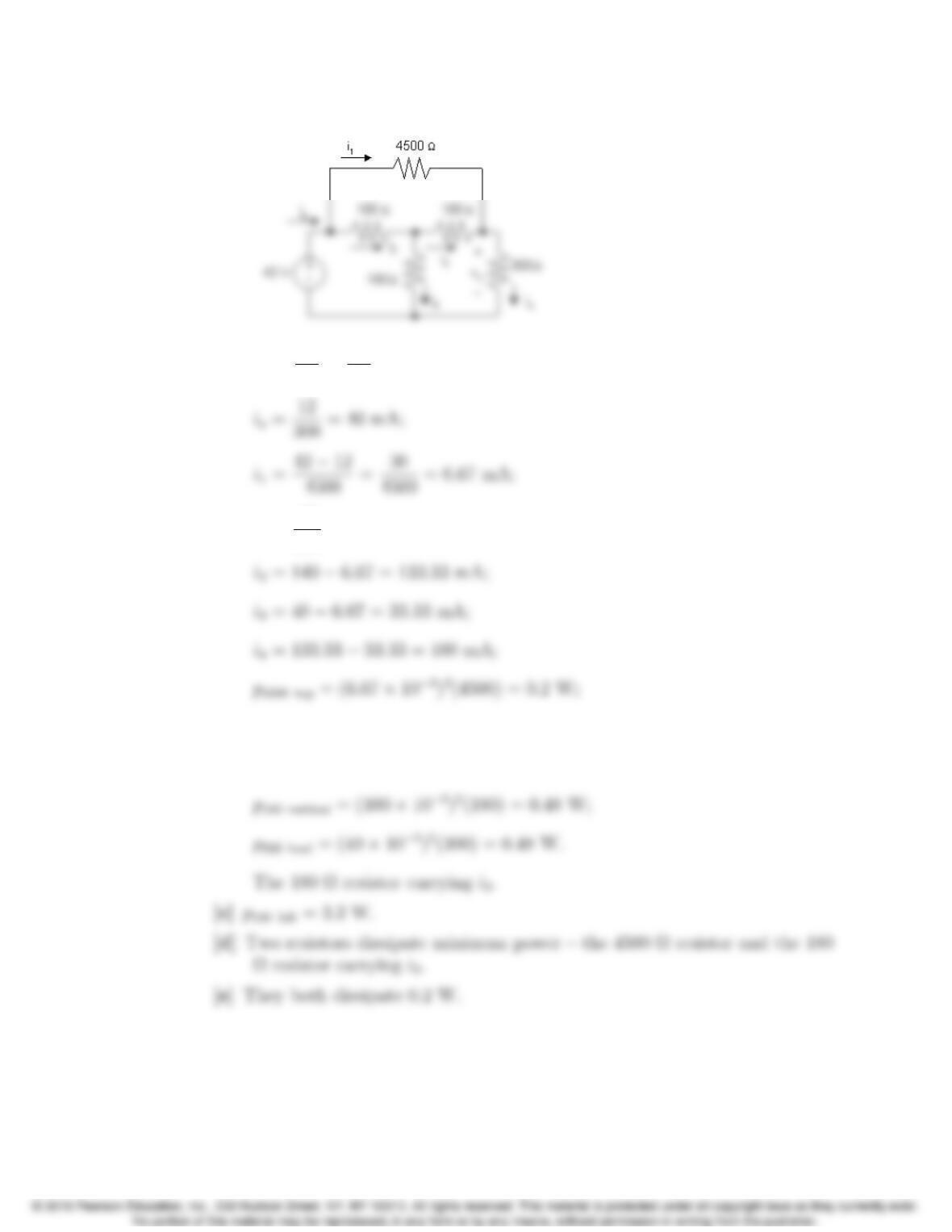
P 3.68 [a] 3.5(3RRL)=3R+RL;
Problems 3–47
[b ]
vo=vi
3.5=42
3.5= 12 V;
ig=42
300 = 140 mA;
p180 left = (133.33 ⇥10−3)2(180) = 3.2 W;
p180 right = (33.33 ⇥10−3)2(180) = 0.2 W;
3–48 CHAPTER 3. Simple Resistive Circuits
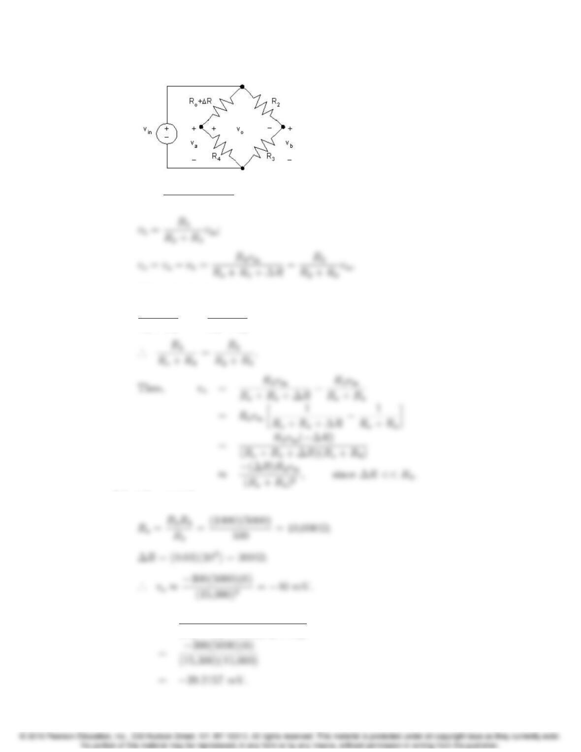
P 3.69 [a ]
va=vinR4
Ro+R4+∆R;
When the bridge is balanced,
R4
Ro+R4
vin =R3
R2+R3
vin;
[b] ∆R=0.03Ro;
[c] vo=(∆R)R4vin
(Ro+R4+∆R)(Ro+R4)
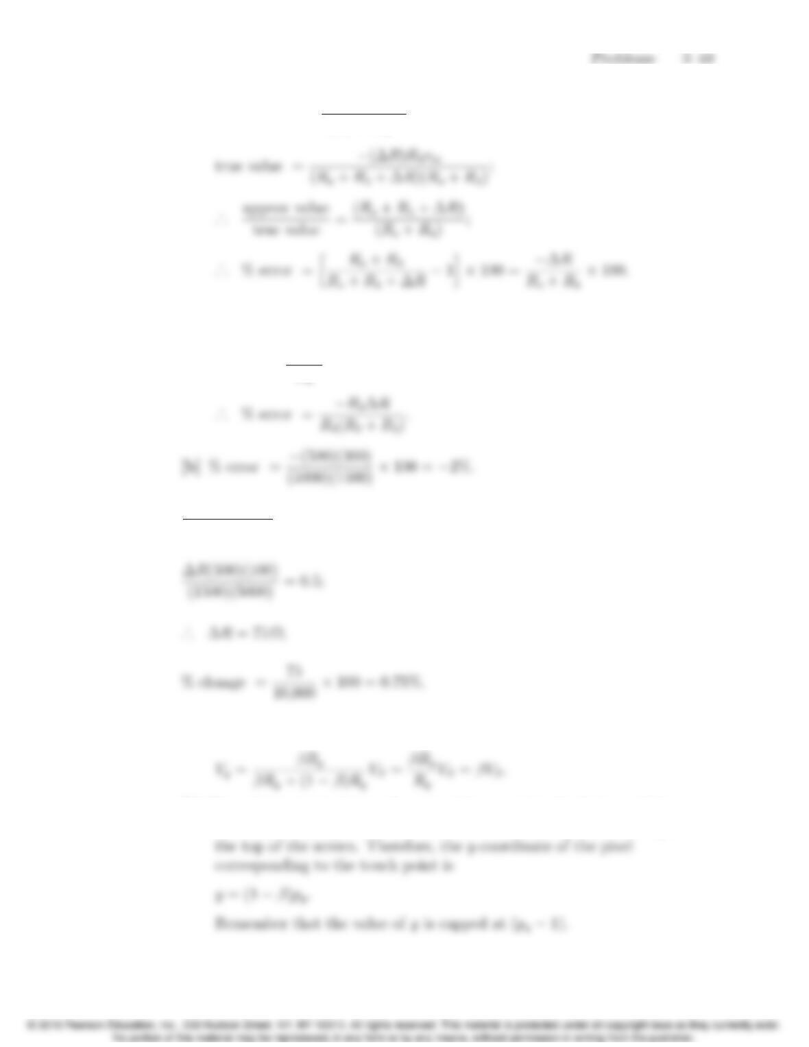
P 3.70 [a] approx value = (∆R)R4vin
(Ro+R4)2;
Note that in the above expression, we take the ratio of the true value to
the approximate value because both values are negative.
But Ro=R2R4
R3
;
P 3.71 ∆R(R3)(100)
(R2+R3)R4
=0.5;
P 3.72 [a] Using the equation for voltage division,
[b] Since βrepresents the touch point with respect to the bottom of the
screen, (1 β) represents the location of the touch point with respect to
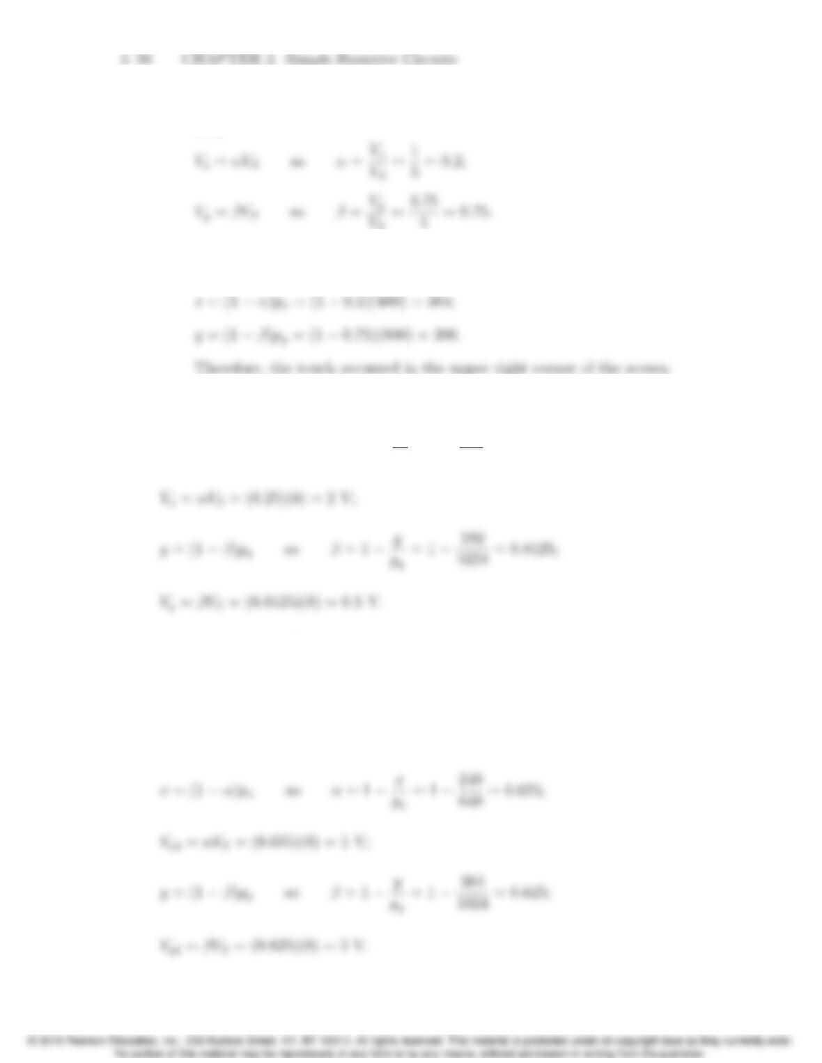
P 3.73 [a] Use the equations developed in the Practical Perspective and in Problem
3.72:
[b] Use the equations developed in the Practical Perspective and in Problem
3.72:
P 3.74 Use the equations developed in the Practical Perspective and in Problem 3.72:
x= (1 α)pxso α=1x
px
=1480
640 =0.25;
P 3.75 From the results of Problem 3.74, the voltages corresponding to the touch
point (480,192) are
Vx1= 2 V; Vy1=6.5V.
Now calculate the voltages corresponding to the touch point (240,384):
Problems 3–51
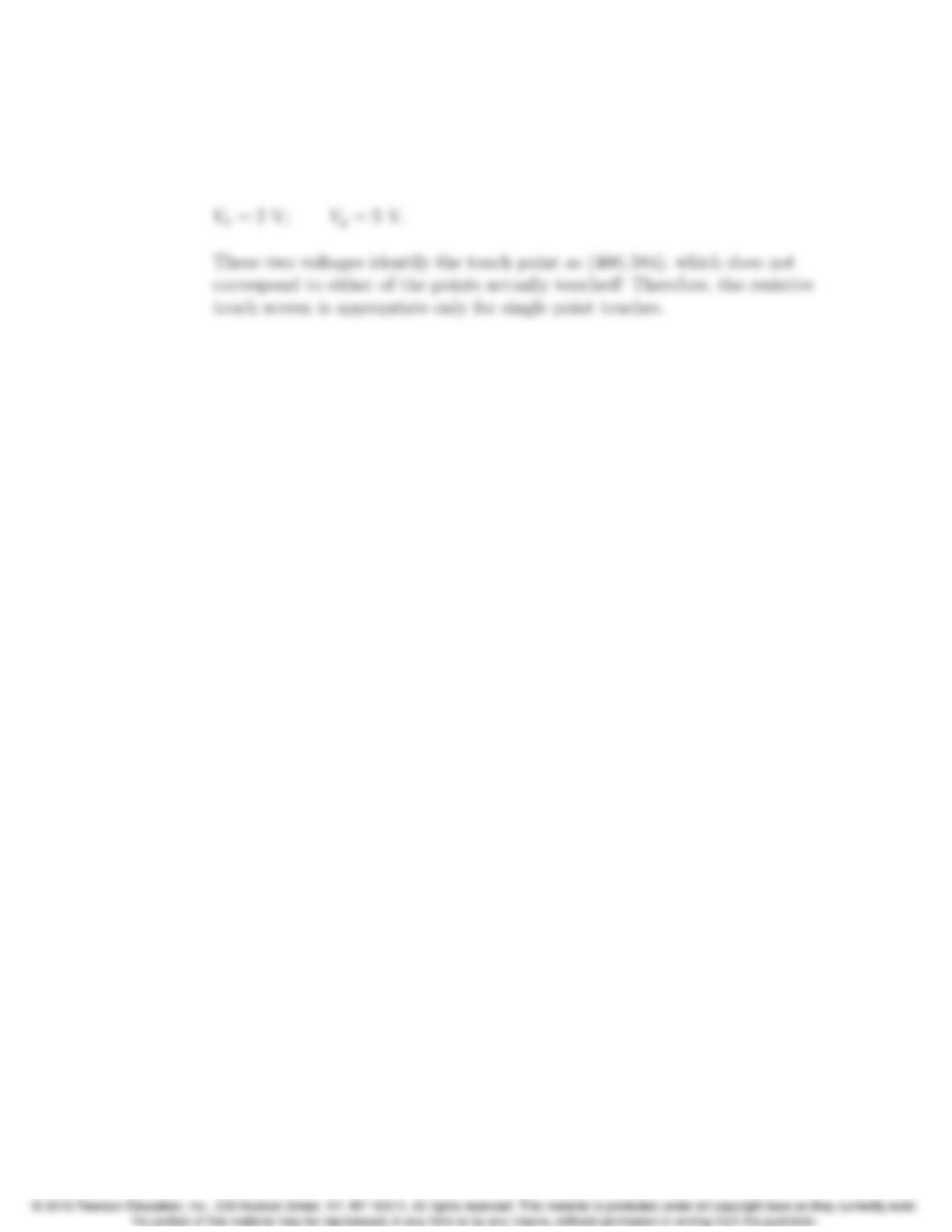
When the screen is touched at two points simultaneously, only the smaller of
the two voltages in the xdirection is sensed. The same is true in the y
direction. Therefore, the voltages actually sensed are