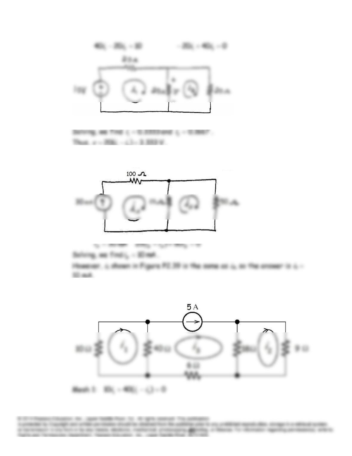
P2.72 The mesh currents and corresponding equations are:
P2.73 First, we select the mesh currents and then write three equations.
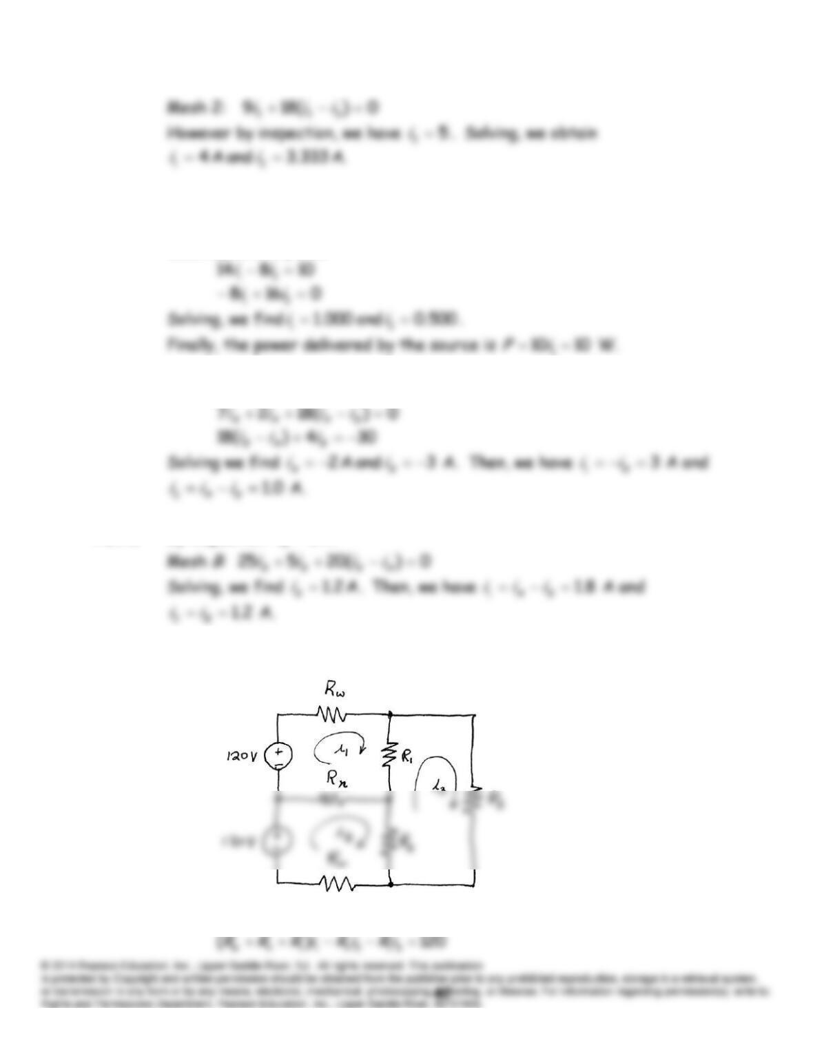
P2.74 We assume that
i
1 is a mesh current flowing around the left-hand mesh
and that
i
2 flows around the right-hand mesh. Writing and simplifying the
mesh equations yields:
P2.75 The mesh (KVL) equations are:
P2.76 By inspection:
3
i
A.
P2.77 (a) First, we select mesh-current variables as shown.
Then, we can write
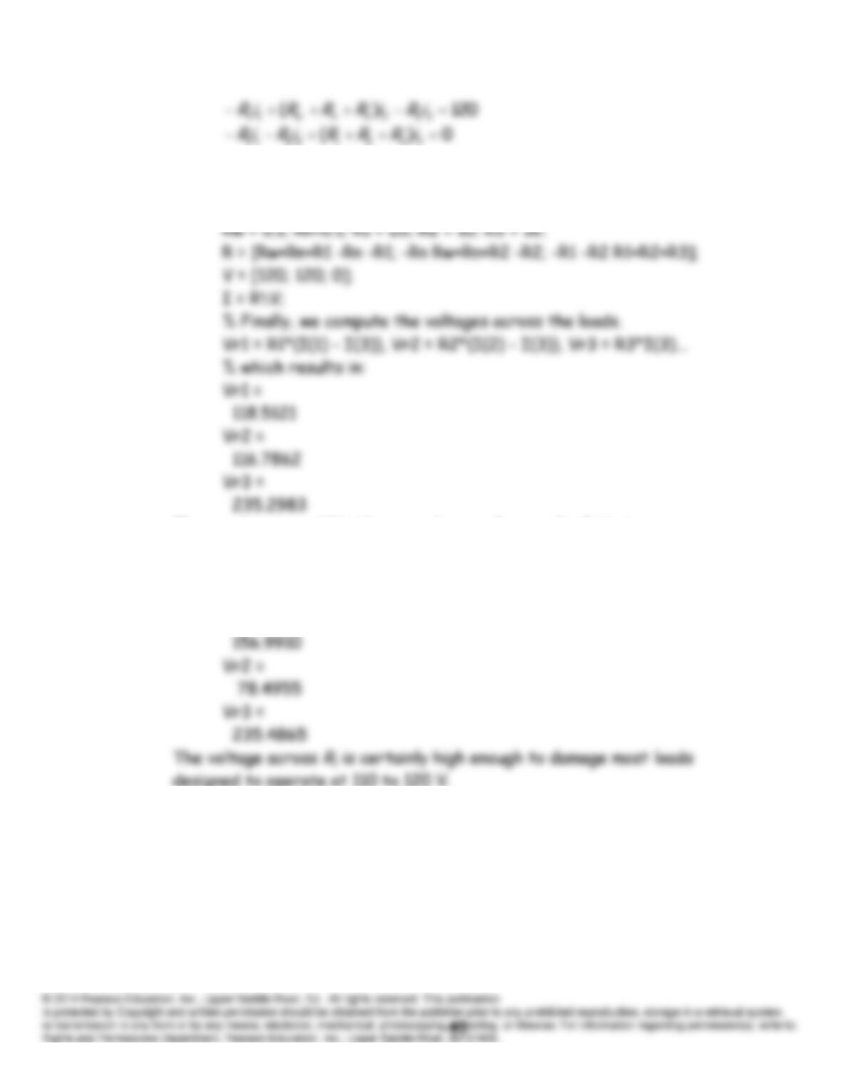
Alternatively, because the network consists of independent voltage
sources and resistances, and all of the mesh currents flow clockwise, we
can enter the matrices directly into MATLAB.
These values are within the normal range for nearly all devices.
(b) Next, we change Rn to a very high value such as 109 which for
practical calculations is equivalent to an open circuit, and again compute
the voltages resulting in:
Vr1 =
designed to operate at 110 to 120 V.
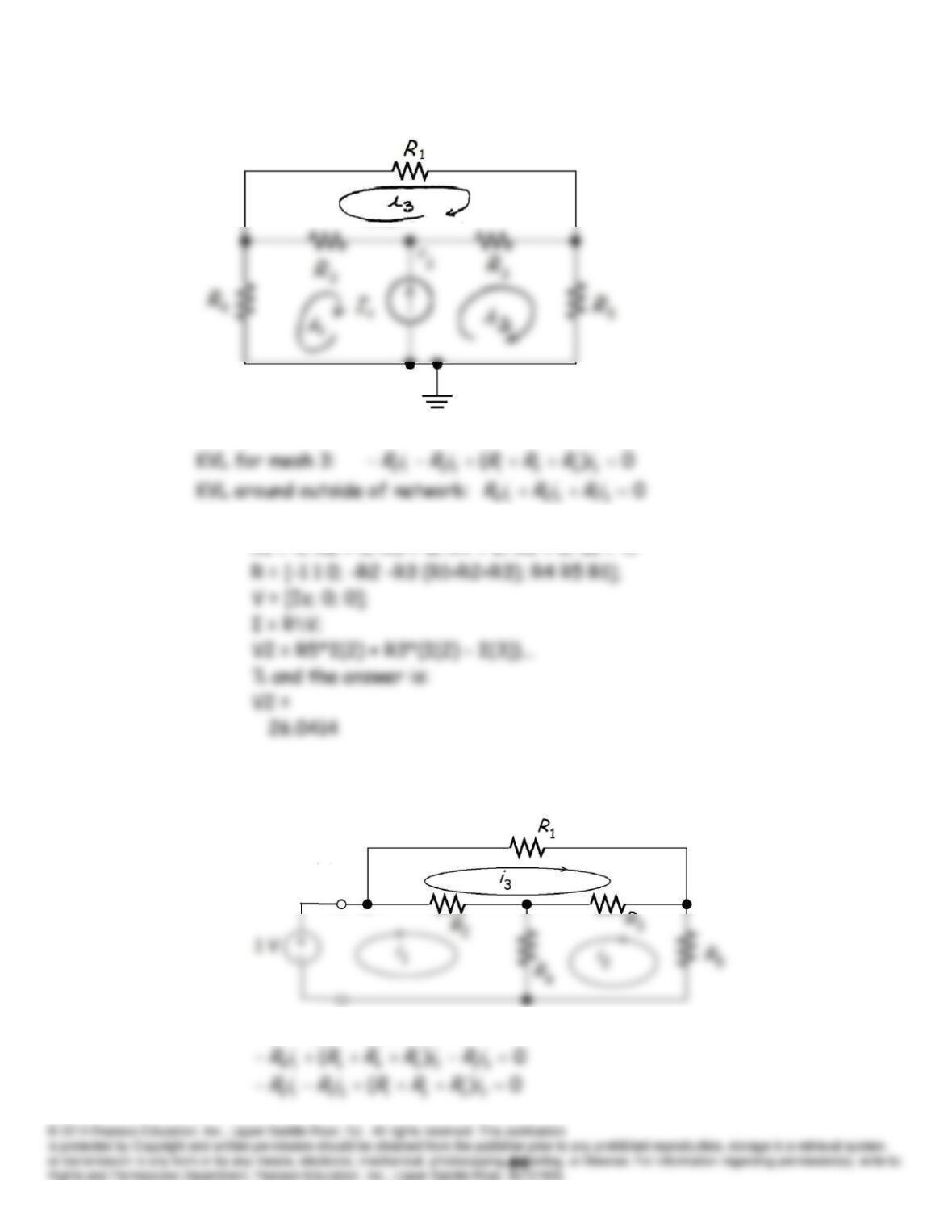
P2.78
Current source in terms of mesh currents:
s
Iii
21
Then using MATLAB:
R1 = 4; R2 = 5; R3 = 8; R4 = 6; R5 = 8; Is = 4;
P2.79
1)( 3224142
iRiRiRR
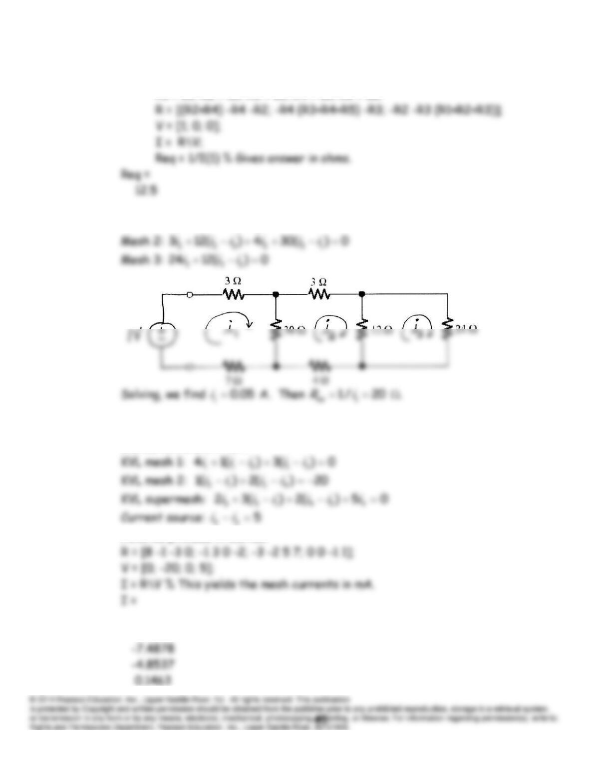
Now using MATLAB:
R1 = 15; R2 = 15; R3 = 15; R4 = 10; R5 = 10;
P2.80 Mesh 1:
1)(3073 2111
iiii
P2.81 We write equations in which voltages are in volts, resistances are in k,
and currents are in mA.
Now, we proceed in Matlab.
-2.7561
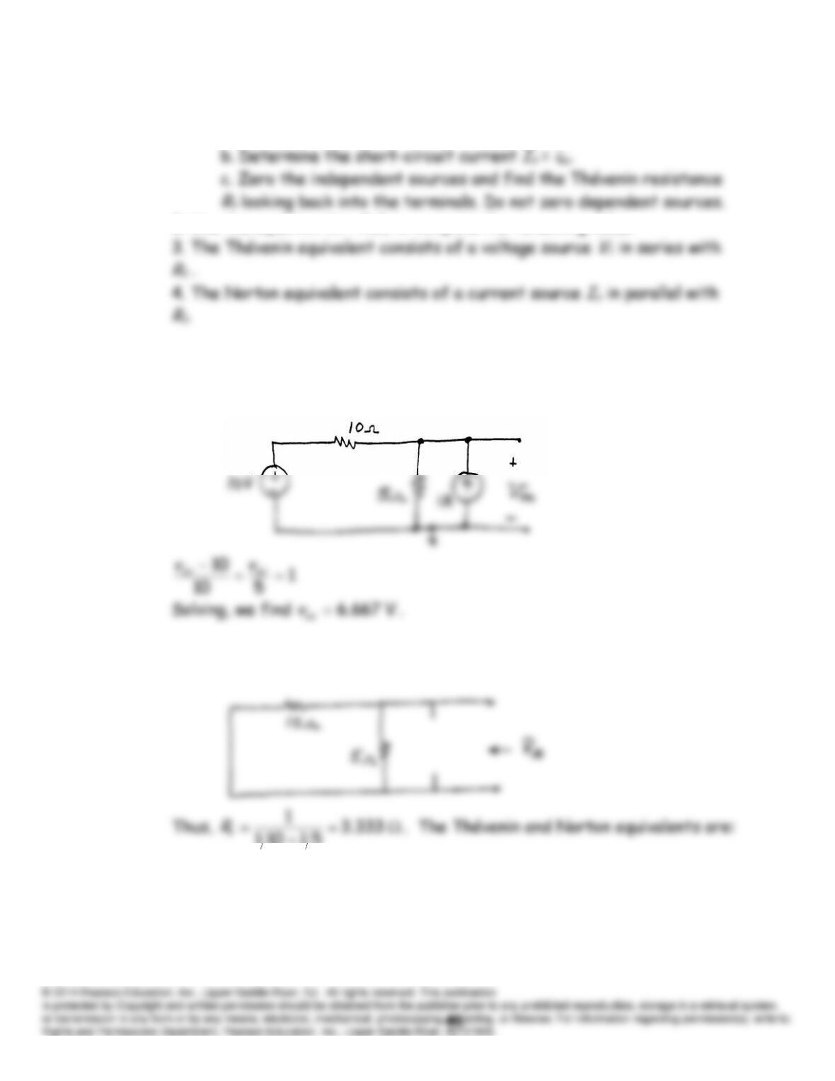
P2.82. 1. Perform two of these:
a. Determine the open-circuit voltage
Vt
=
v
oc.
2. Use the equation
Vt
=
RtIn
to compute the remaining value.
P2.83* First, we write a node voltage equation to solve for the open-circuit
voltage:
Then zeroing the sources, we have this circuit:
51101
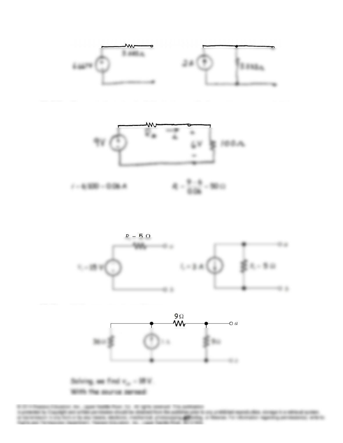
P2.84* The equivalent circuit of the battery with the resistance connected is
P2.85 The 9- resistor has no effect on the equivalent circuits because the
voltage across the 12-V source is independent of the resistor value.
P2.86 With open-circuit conditions:
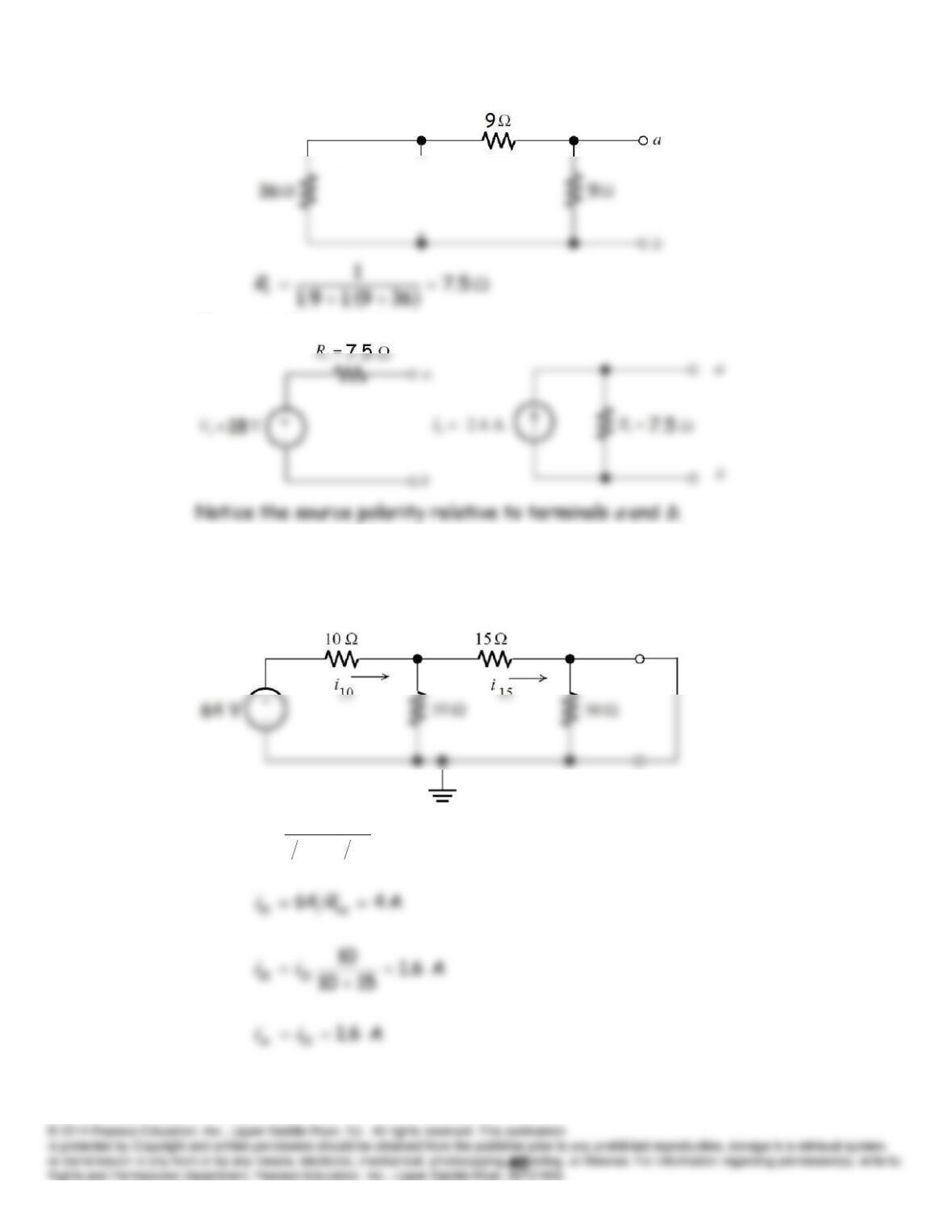
The equivalent circuits are:
P2.87 First, we combine the 30- resistances that are in parallel replacing
them with a 15- resistance. Then, we solve the network with a short
circuit:
16
151101
1
10
eq
R
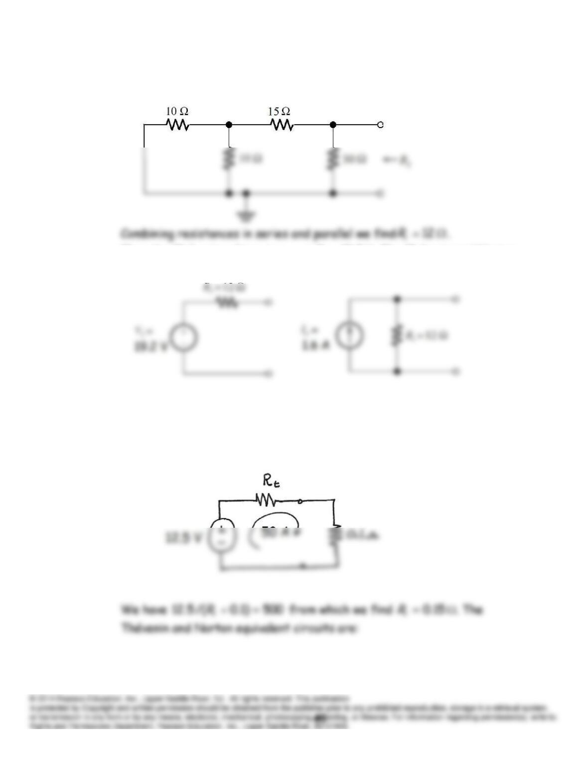
Zeroing the source, we have:
Then the Thévenin voltage is
V 2.19
tsctRiv
. The Thévenin and Norton
equivalents are:
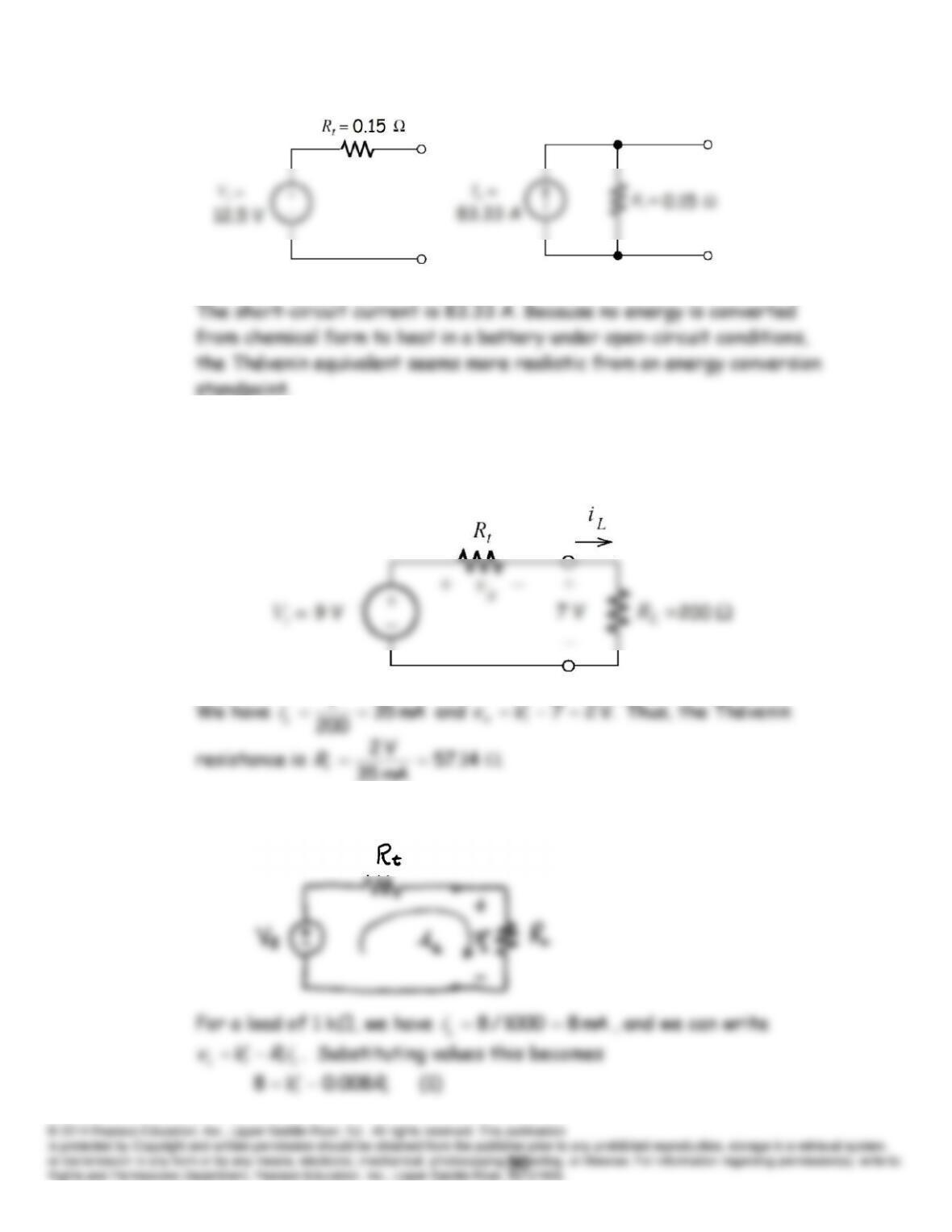
P2.88 The Thévenin voltage is equal to the open-circuit voltage which is 12.5 V.
The equivalent circuit with the 0.1- load connected is:
P2.89 The Thévenin voltage is equal to the open-circuit voltage, which is 9 V.
The circuit with the load attached is:
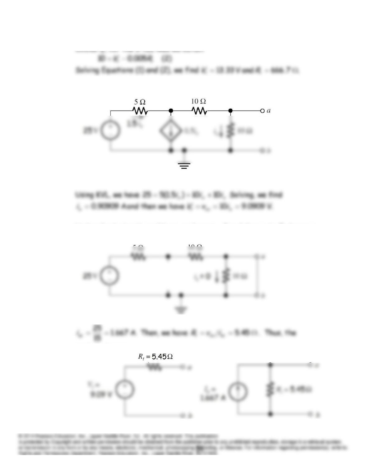
P2.90 The equivalent circuit with a load attached is:
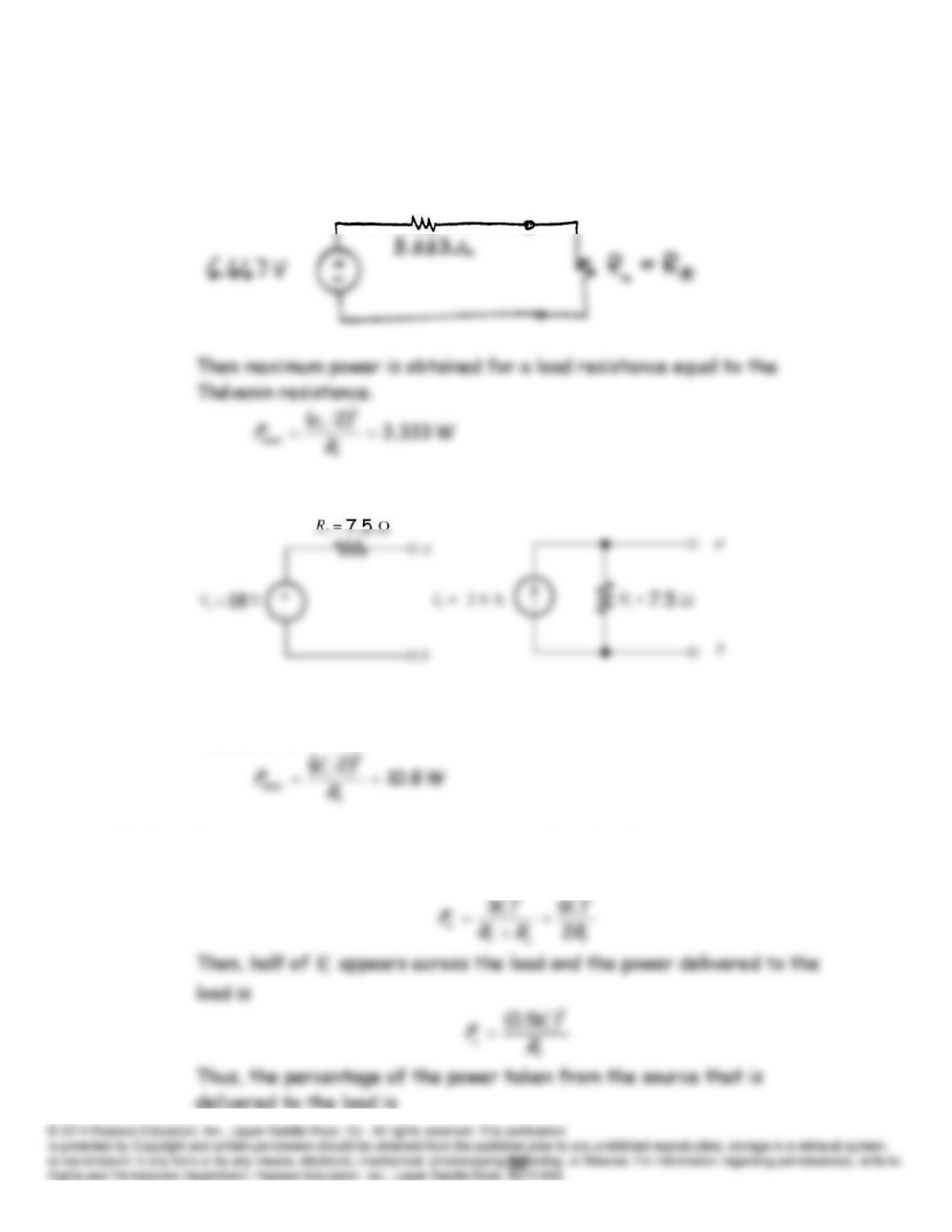
P2.91 Open-circuit conditions:
Under short-circuit conditions, we have
ix
0 and the controlled source
becomes an open circuit:
equivalents are:
P2.92 As is Problem P2.83, we find the Thévenin equivalent:
P2.93 As in Problem P2.86, we find the Thévenin equivalent:
Then, maximum power is obtained for a load resistance equal to the
Thévenin resistance.
P2.94 For maximum power conditions, we have
t
LRR
. The power taken from
the voltage source is