2–20 CHAPTER 2. Circuit Elements
[b] p20mA =−(0.02)vo=−(0.02)(25) = −0.5 W;
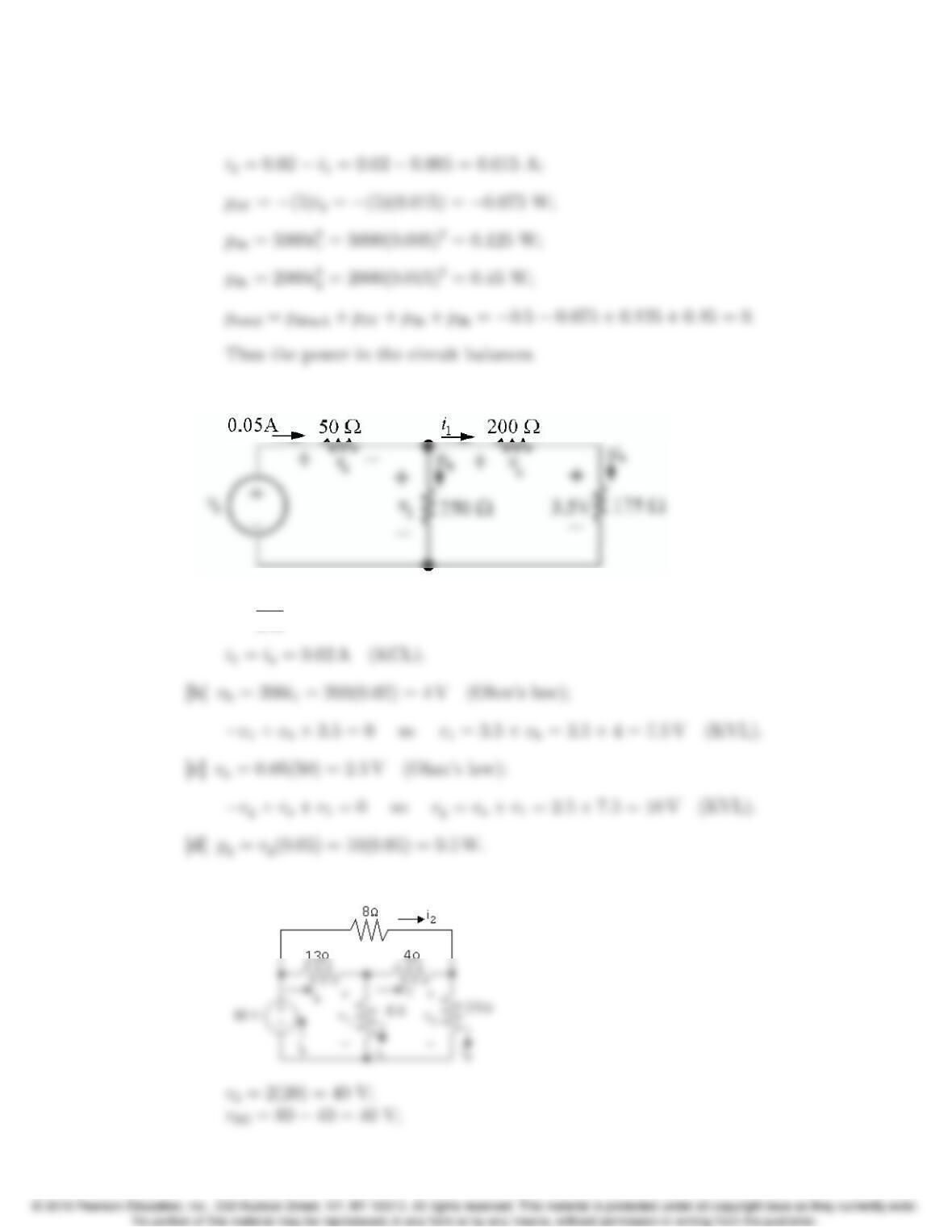
P 2.21 Label the unknown resistor voltages and currents:
[a] ia=3.5
175 =0.02 A (Ohm’s law);
P 2.22 [a]
Problems 2–21
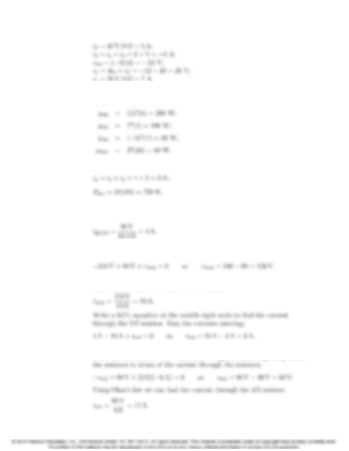
i1= 28 V/4Ω= 7 A.
[b] i4=i1+i3=7−3 = 4 A.
p13Ω=4
2(13) = 208 W;
[c] XPdis = 208 + 200 + 196 + 36 + 80 = 720 W;
P 2.23 [a] Start with the 22.5Ωresistor. Since the voltage drop across this resistor is
90 V, we can use Ohm’s law to calculate the current:
Next we can calculate the voltage drop across the 15 Ωresistor by writing
a KVL equation around the outer loop of the circuit:
Now that we know the voltage drop across the 15 Ωresistor, we can use
Ohm’s law to find the current in this resistor:
Write a KVL equation clockwise around the upper right loop, starting
below the 4 Ωresistor. Use Ohm’s law to express the voltage drop across
2–22 CHAPTER 2. Circuit Elements
Write a KCL equation at the middle node. Sum the currents entering:
Use Ohm’s law to calculate the voltage drop across the 20 Ωresistor:
All of the voltages and currents calculated above are shown in the figure
below:
Calculate the power dissipated by the resistors using the equation
pR=Ri2
R:
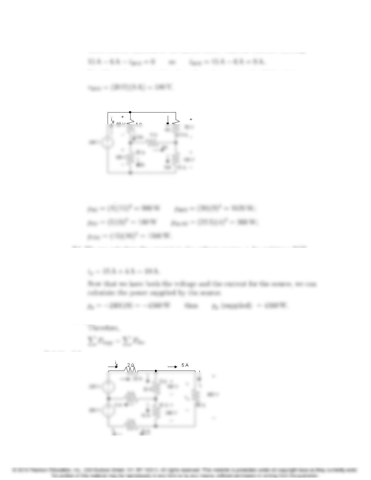
[b] We can calculate the current in the voltage source, igby writing a KCL
equation at the top middle node:
[c] XPdis = 900 + 1620 + 180 + 360 + 1500 = 4560 W.
P 2.24 [a]
Problems 2–23
vo= 20(8) + 16(15) = 400 V;
[b] XPdis = (25)2(2) + (20)2(8) + (5)2(4) + (15)216 + (20)22 + (5)2(80)
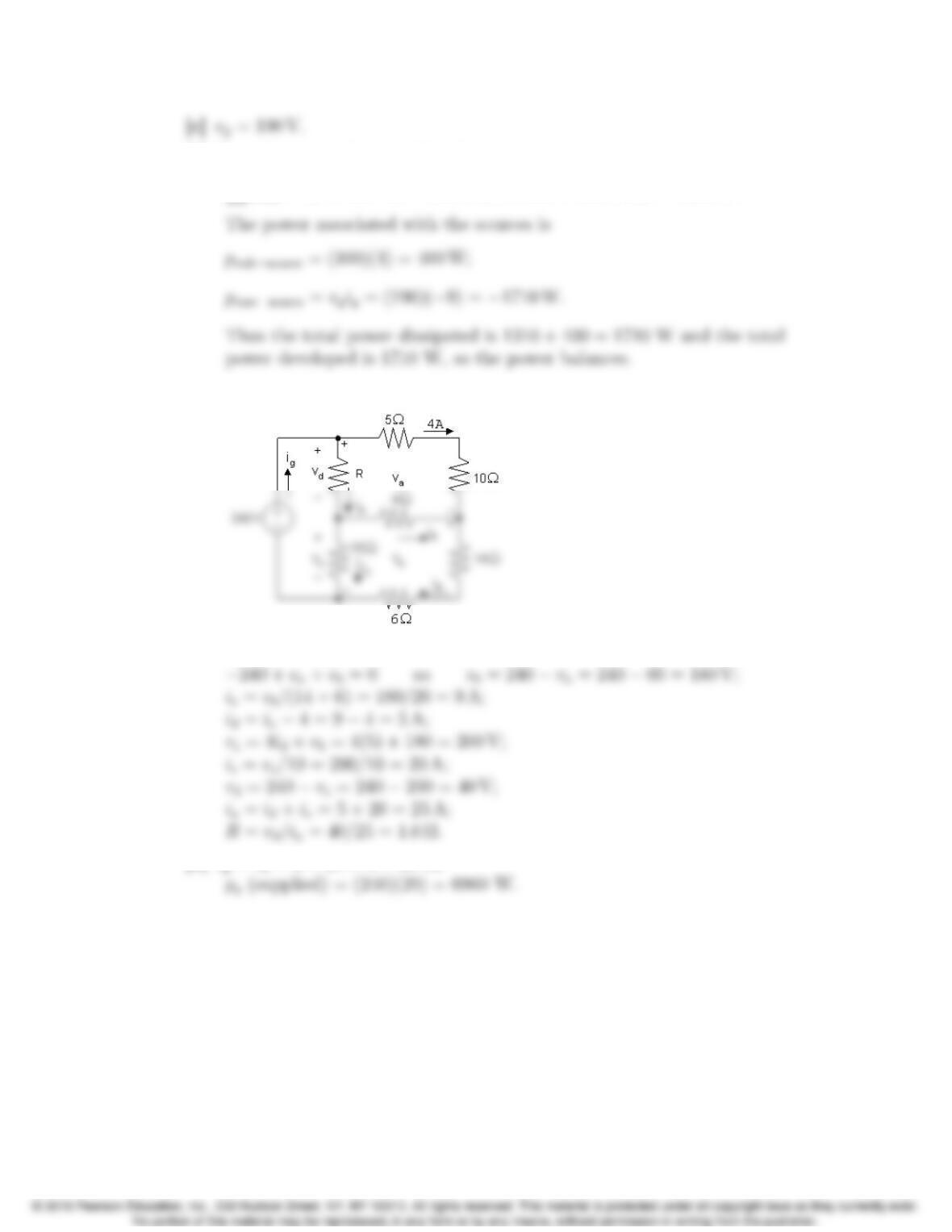
P 2.25 [a]
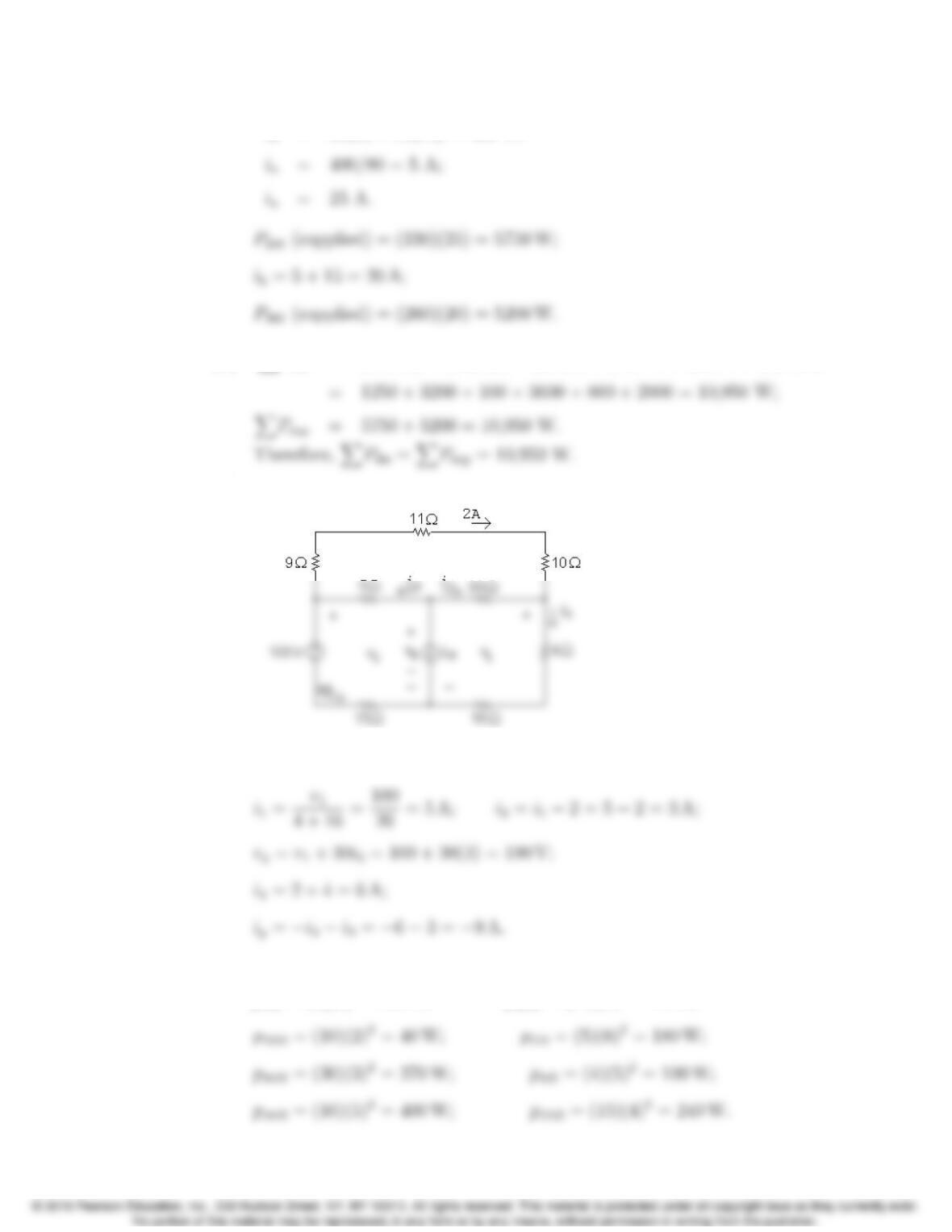
v2= 100 + 4(15) = 160 V; v1= 160 −(9 + 11 + 10)(2) = 100 V;
[b] Calculate power using the formula p=Ri2:
p9Ω= (9)(2)2= 36 W; p11 Ω= (11)(2)2= 44 W;
2–24 CHAPTER 2. Circuit Elements
[d] Sum the power dissipated by the resistors:
Xpdiss = 36 + 44 + 40 + 180 + 270 + 100 + 400 + 240 = 1310 W.
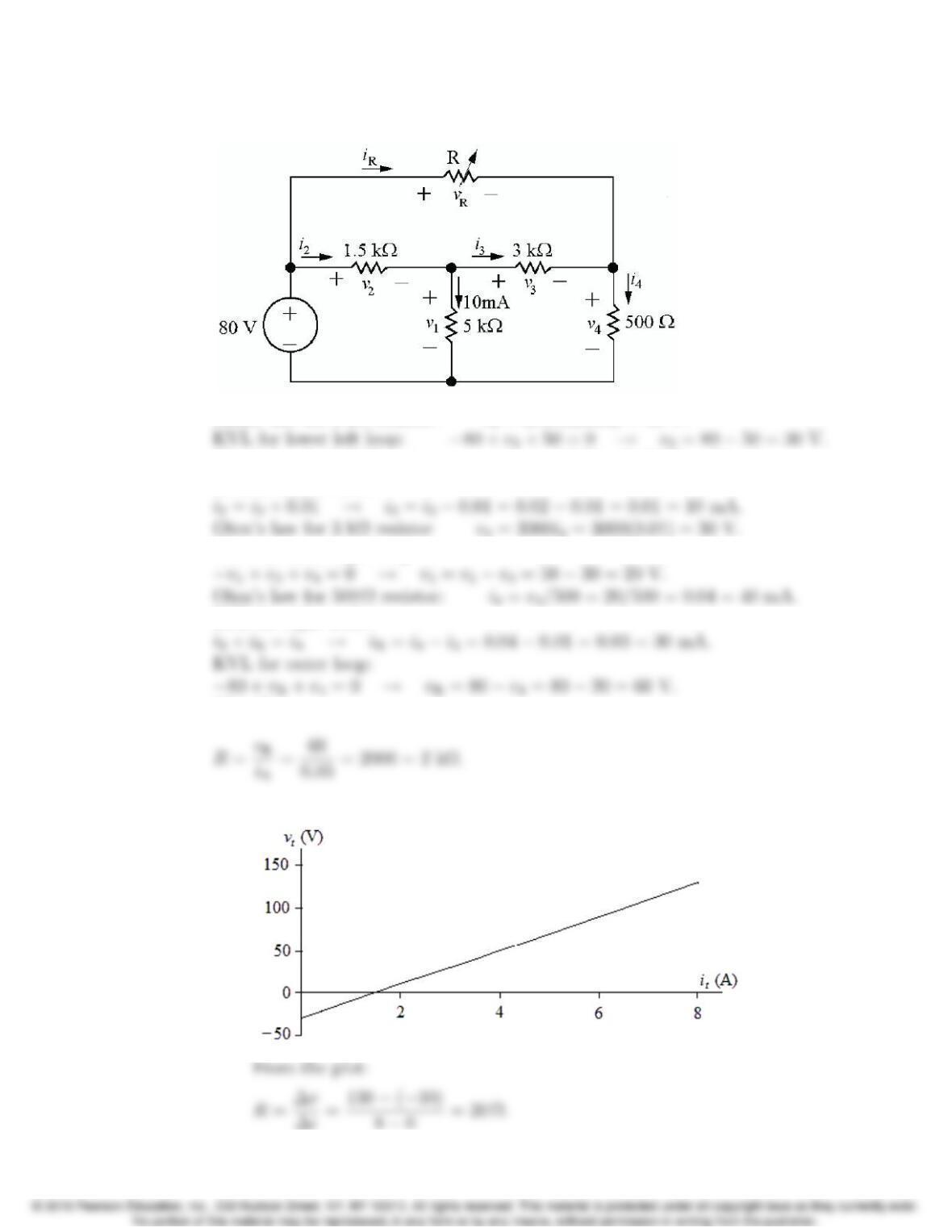
P 2.26 [a]
va= (5 + 10)(4) = 60 V;
[b] ig=ia+ 4 = 25 + 4 = 29 A;
Problems 2–25
P 2.27 Label all unknown resistor voltages and currents:
Ohms’ law for 5 kΩresistor: v1= (0.01)(5000) = 50 V.
Ohm’s law for 1.5 kΩresistor: i2=v2/1500 = 30/1500 = 20 mA.
KCL at center node:
KVL for lower right loop:
KCL for right node:
Therefore,
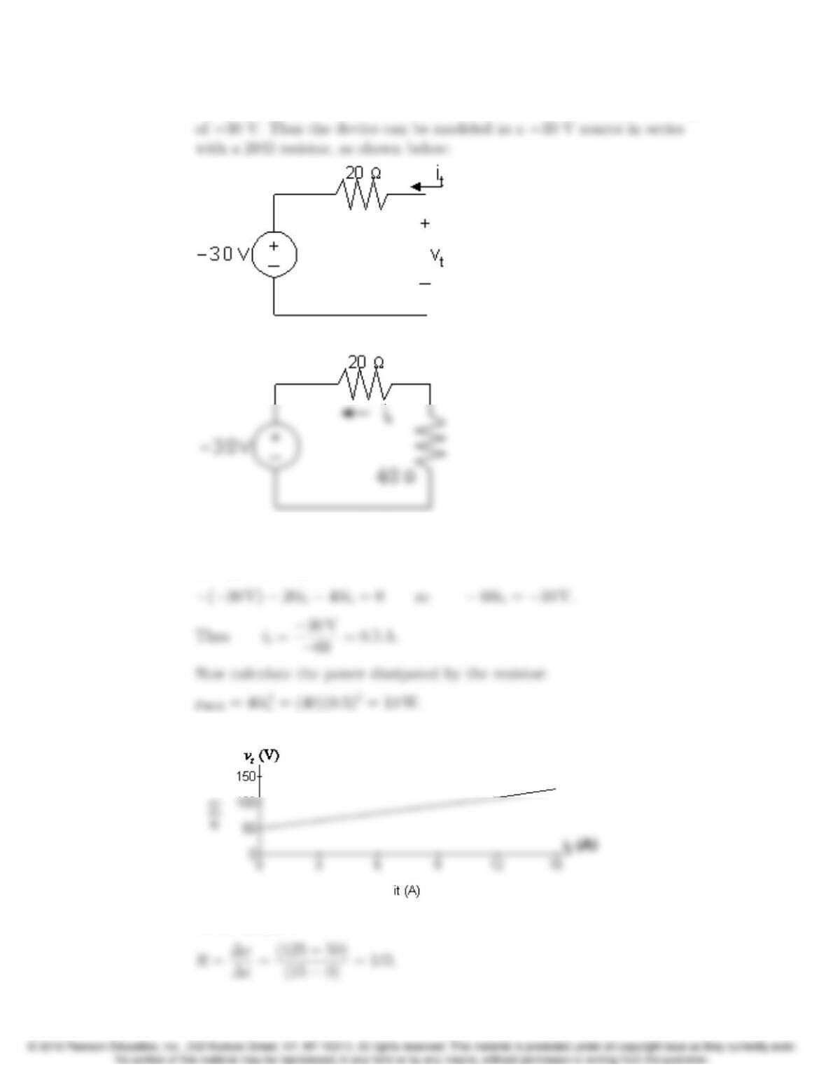
P 2.28 [a] Plot the v—icharacteristic:
2–26 CHAPTER 2. Circuit Elements
When it= 0, vt=−30 V; therefore the ideal voltage source has a voltage
[b] We attach a 40 Ωresistor to the device model developed in part (a):
Write a KVL equation clockwise around the circuit, using Ohm’s law to
express the voltage drop across the resistors in terms of the current it
through the resistors:
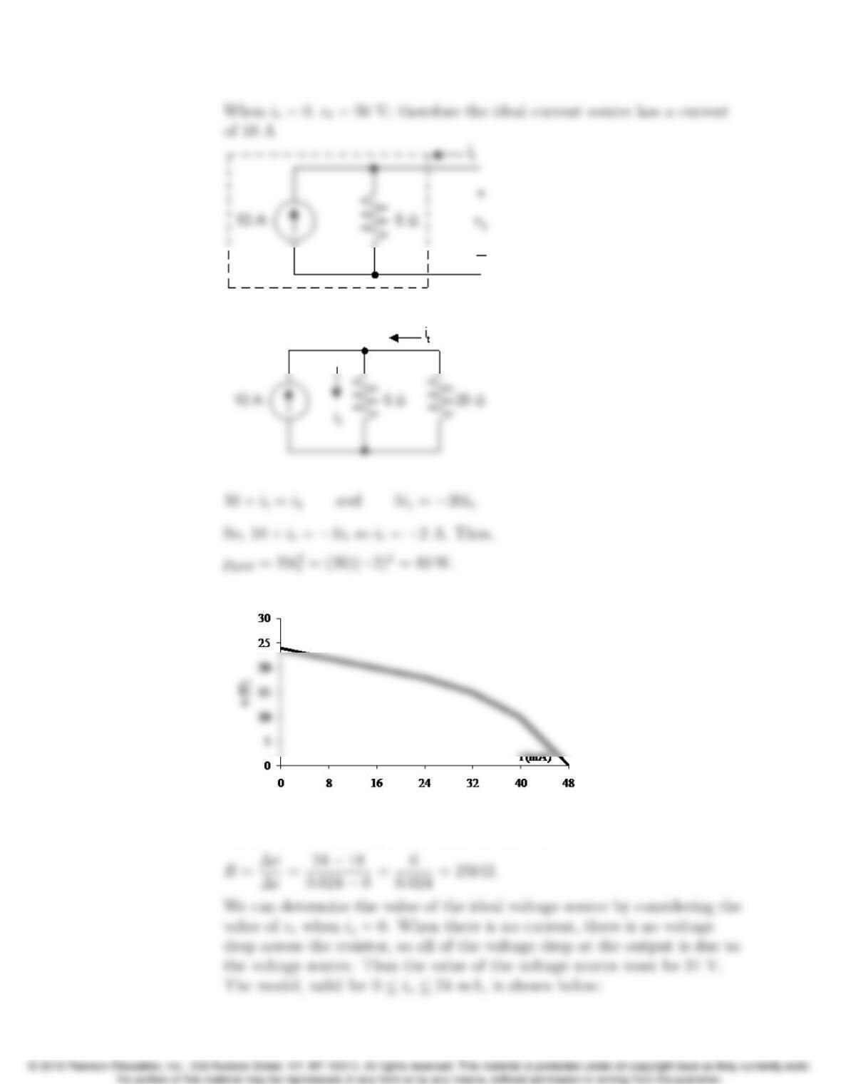
P 2.29 [a] Plot the v−icharacteristic
From the plot:
Problems 2–27
[b]
P 2.30 [a] Begin by constructing a plot of voltage versus current:
[b] Since the plot is linear for 0 ≤is≤24 mA amd since R=∆v/∆i, we can
calculate Rfrom the plotted values as follows:
2–28 CHAPTER 2. Circuit Elements
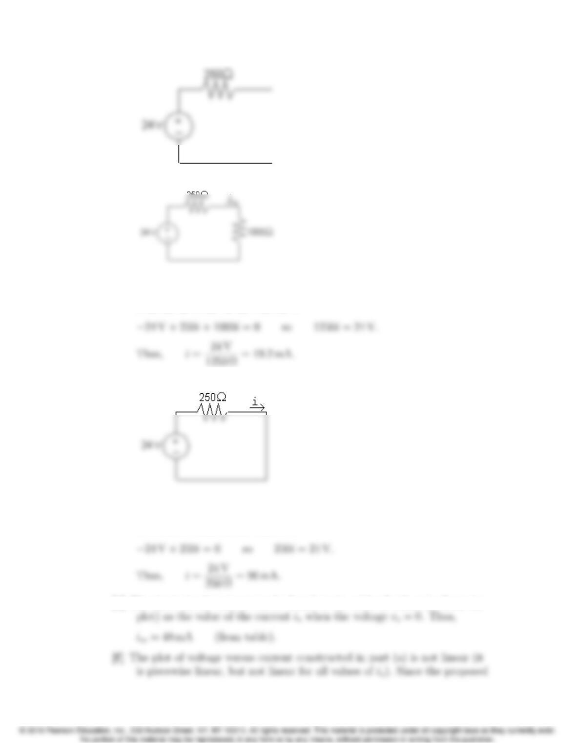
[c] The circuit is shown below:
Write a KVL equation in the clockwise direction, starting below the
voltage source. Use Ohm’s law to express the voltage drop across the
resistors in terms of the current i:
[d] The circuit is shown below:
Write a KVL equation in the clockwise direction, starting below the
voltage source. Use Ohm’s law to express the voltage drop across the
resistors in terms of the current i:
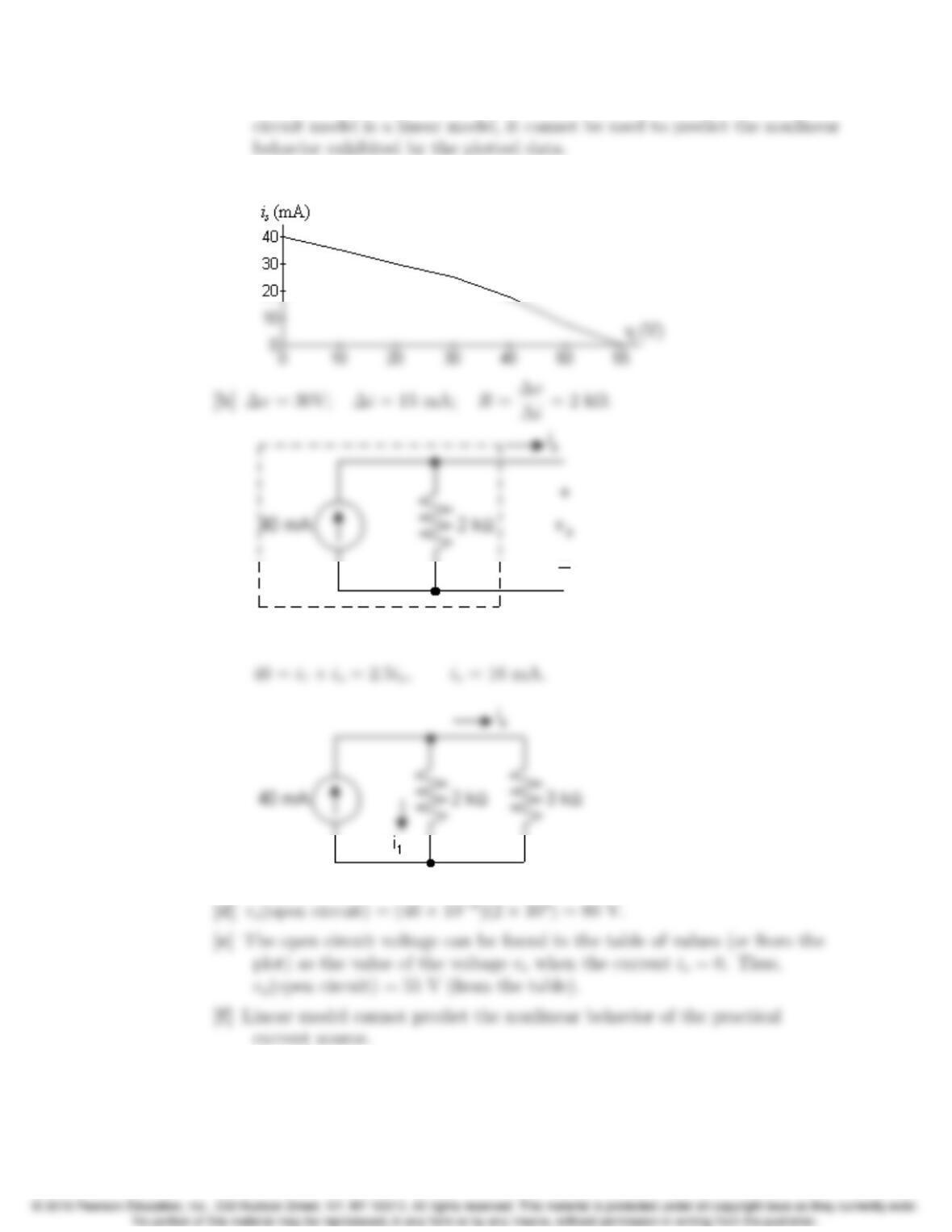
[e] The short circuit current can be found in the table of values (or from the
Problems 2–29
P 2.31 [a]
[c] 2000i1= 3000is,i
1=1.5is;
2–30 CHAPTER 2. Circuit Elements
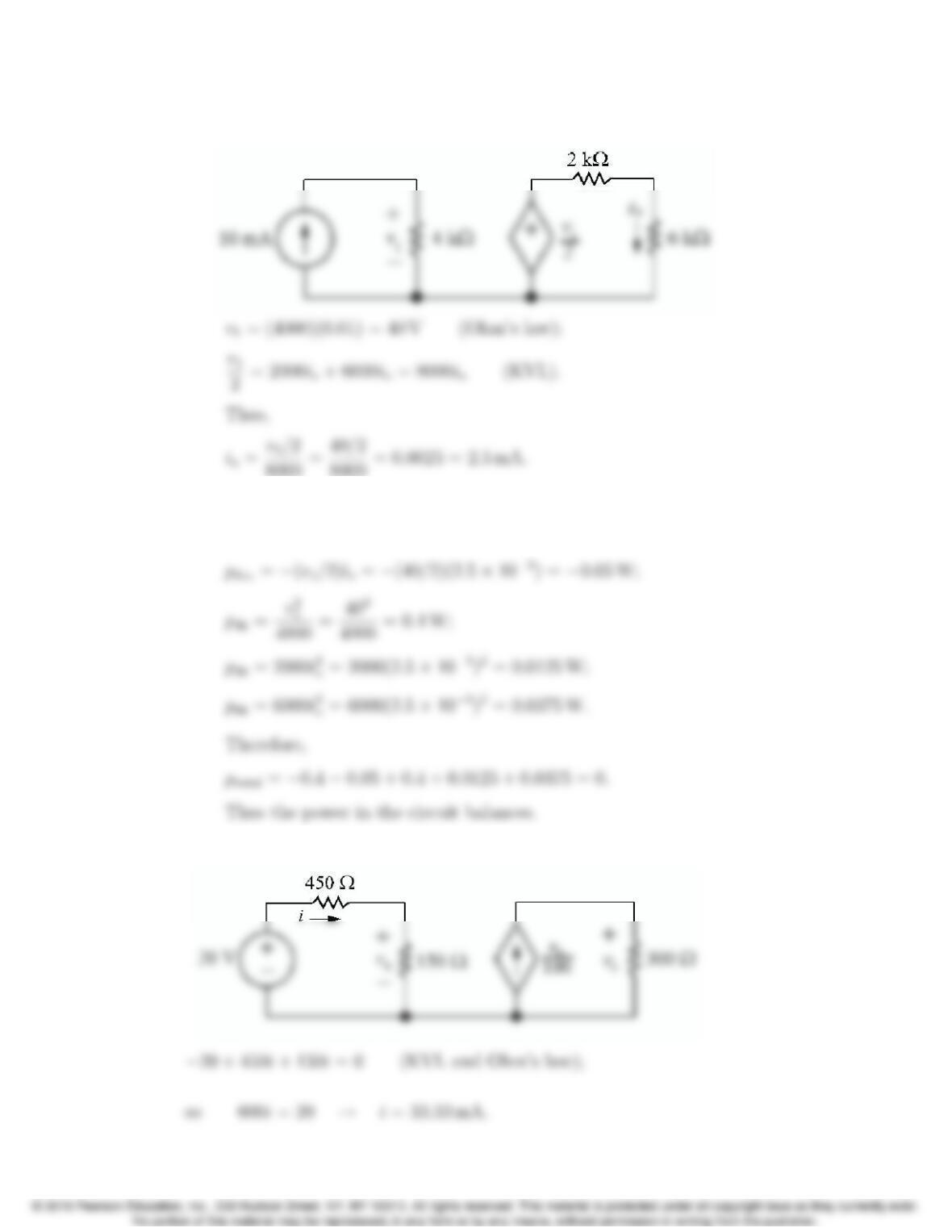
P 2.32 [a] The circuit:
8000 =40/2
8000 =0.0025 = 2.5 mA.
[b] Calculate the power for all components:
p10mA =−(0.01)v1=−(0.01)(40) = −0.4 W;
P 2.33 Label unknown current:
Problems 2–31
vx= 150i= 150(0.0333) = 5 V (Ohm’s law);
Calculate the power for all components:
p20V =−20i=−20(0.0333) = −0.667 W;
Thus the total power absorbed is
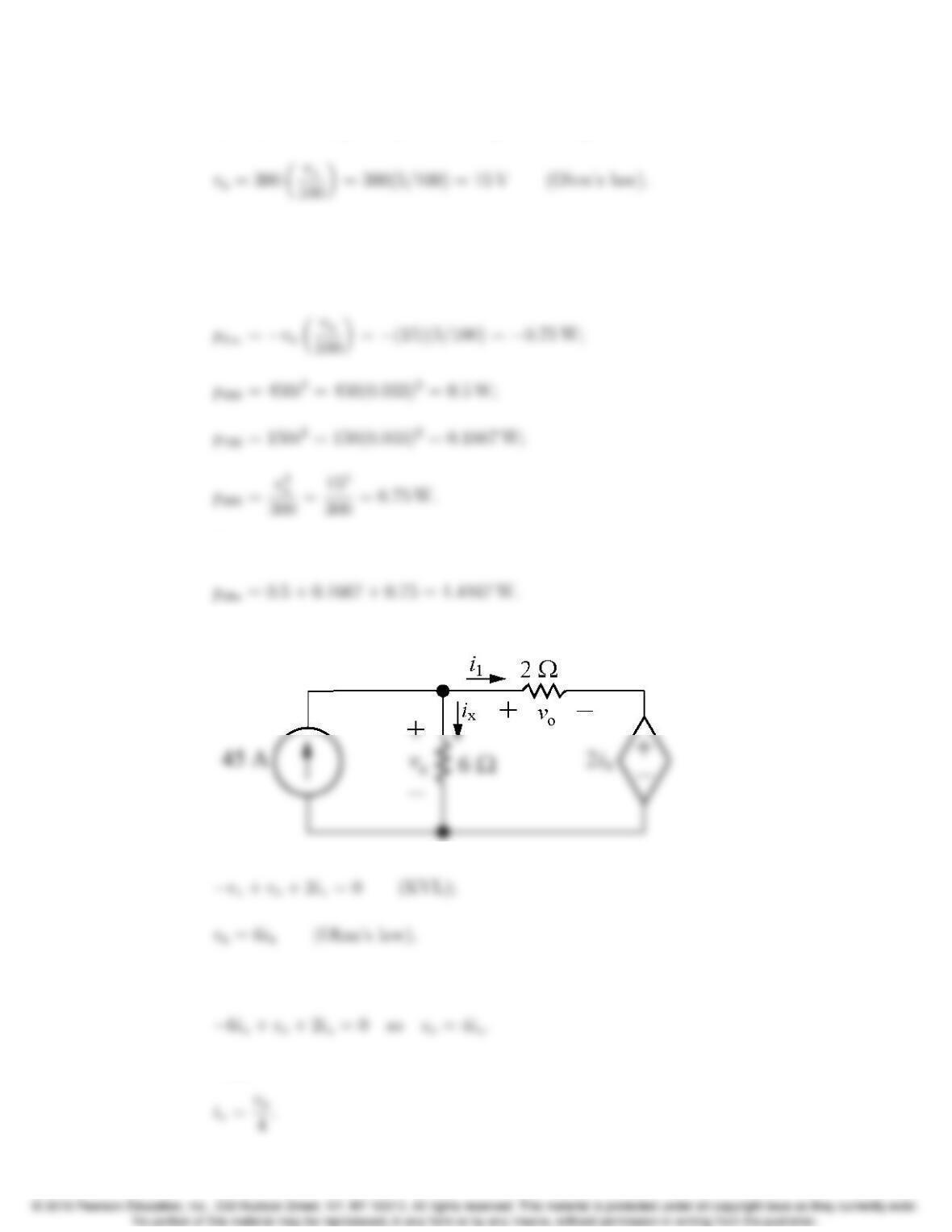
P 2.34 Label unknown voltage and current:
Therefore
Thus
2–32 CHAPTER 2. Circuit Elements
Also,
Substituting for the currents ixand i1:
Thus
The only two circuit elements that could supply power are the two sources, so
calculate the power for each source:
P 2.35 [a] io= 0 because no current can exist in a single conductor connecting two
[b]
Problems 2–33
P 2.36 [a] 12 −2iσ=5i∆;
5i∆=8iσ+2iσ= 10iσ.
[b] ig= current out of the positive terminal of the 12 V source;
vd= voltage drop across the 8i∆source;
ig=i∆+iσ+8i∆=9i∆+iσ= 19 A;
P 2.37 40i2+5
40 +5
10 = 0; i2=−15.625 mA;
P 2.38 iE−iB−iC= 0;
iC=βiBtherefore iE= (1 + β)iB;
2–34 CHAPTER 2. Circuit Elements
P 2.39 Here is Equation 2.21:
iB=(VCCR2)/(R1+R2)−V0
(R1R2)/(R1+R2) + (1 + β)RE
;
iB=6−0.6
24,000 + 50(120) =5.4
30,000 =0.18 mA;
i2=vbd
R2
=1.68
60,000 = 28 µA;
P 2.40 [a]
[b]
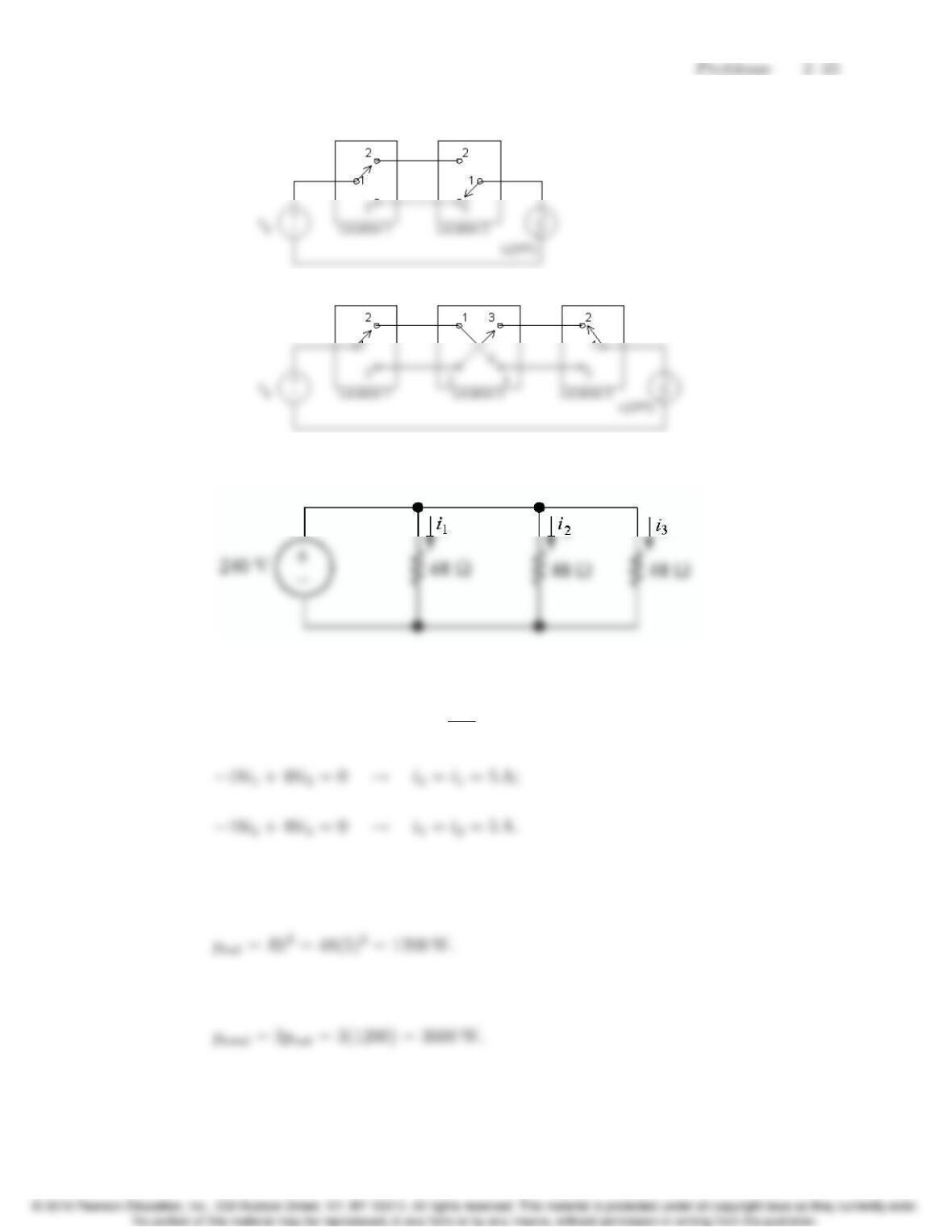
P 2.41 Each radiator is modeled as a 48 Ωresistor:
Write a KVL equation for each of the three loops:
−240 + 48i1=0 →i1=240
48 = 5 A;
Therefore, the current through each radiator is 5 A and the power for each
radiator is
There are three radiators, so the total power for this heating system is
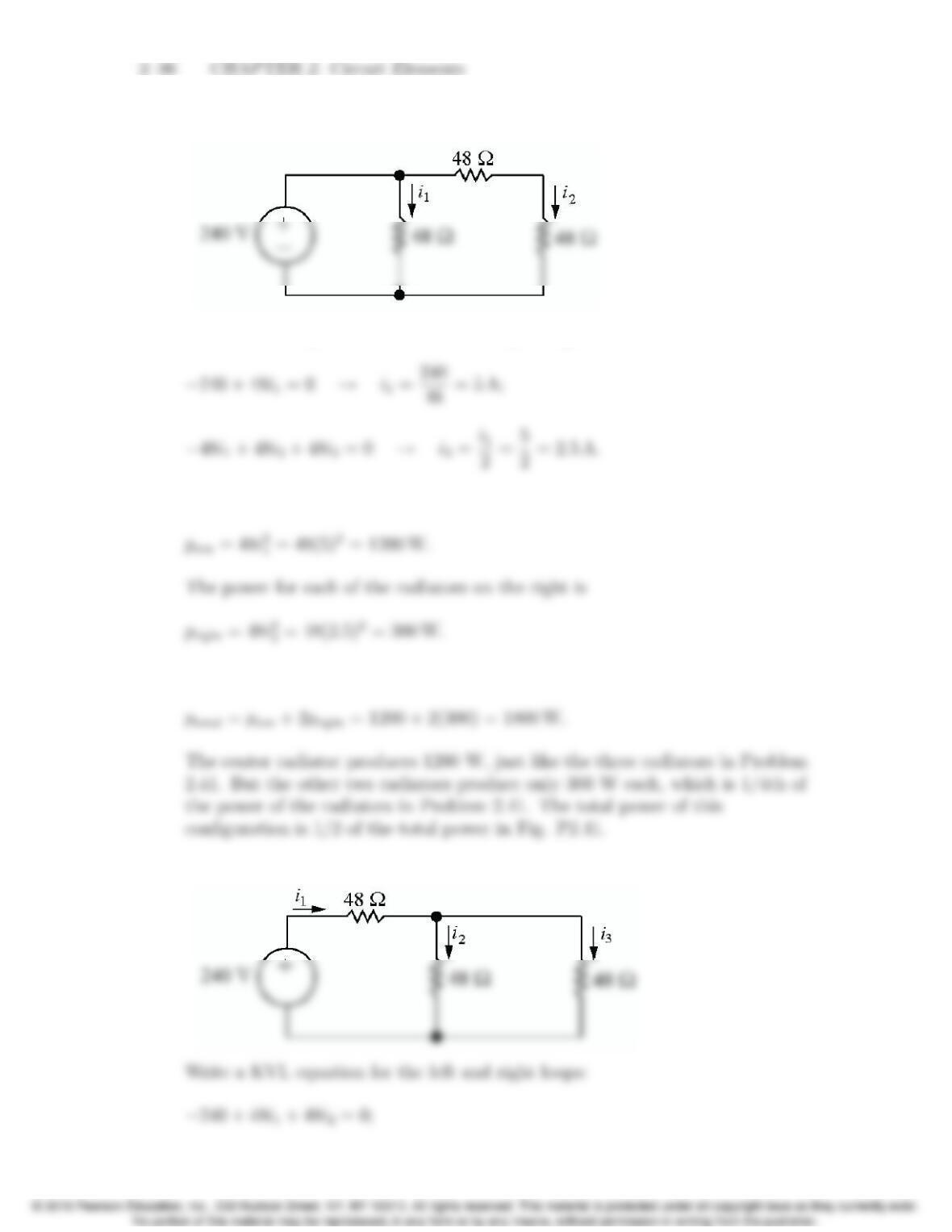
P 2.42 Each radiator is modeled as a 48 Ωresistor:
Write a KVL equation for the left and right loops:
The power for the center radiator is
Thus the total power for this heating system is
P 2.43 Each radiator is modeled as a 48 Ωresistor:
Problems 2–37
Write a KCL equation at the top node:
Substituting into the first KVL equation gives
Solve for the currents i1and i3:
Calculate the power for each radiator using the current for each radiator:
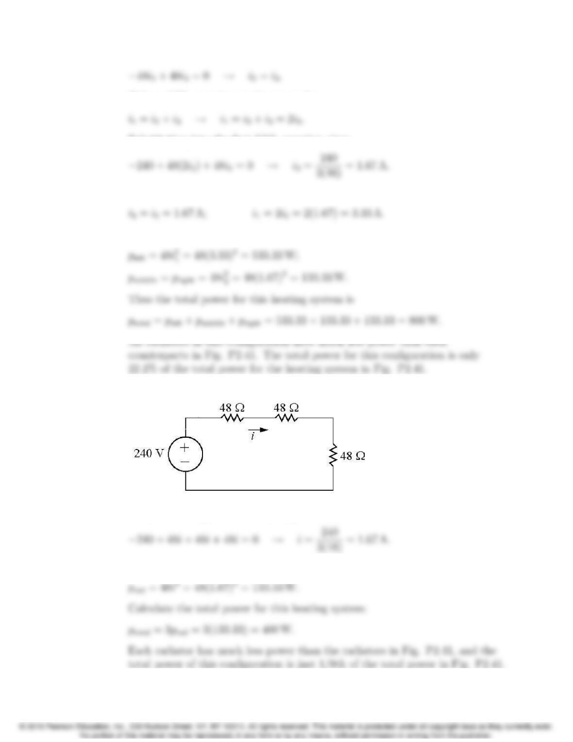
P 2.44 Each radiator is modeled as a 48 Ωresistor:
Write a KVL equation for this loop:
Calculate the power for each radiator: