Circuit Elements
Assessment Problems
AP 2.1
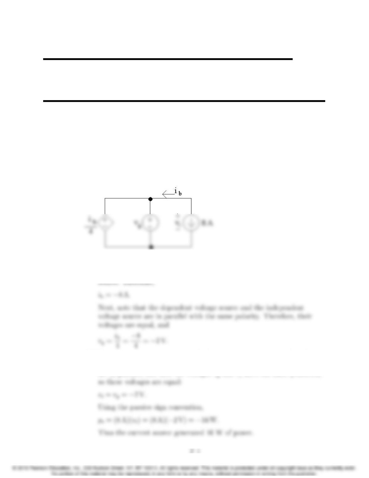
[a] Note that the current ibis in the same circuit branch as the 8 A current
source; however, ibis defined in the opposite direction of the current
[b] To find the power associated with the 8 A source, we need to find the
voltage drop across the source, vi. Note that the two independent sources
are in parallel, and that the voltages vgand v1have the same polarities,
2
2–2 CHAPTER 2. Circuit Elements
AP 2.2
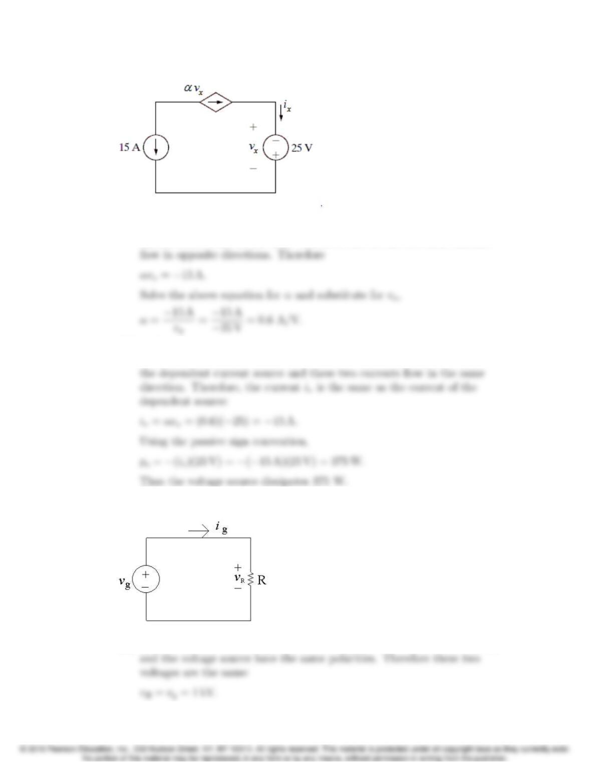
[a] Note from the circuit that vx=−25 V. To find αnote that the two
current sources are in the same branch of the circuit but their currents
[b] To find the power associated with the voltage source we need to know the
current, iv. Note that this current is in the same branch of the circuit as
AP 2.3
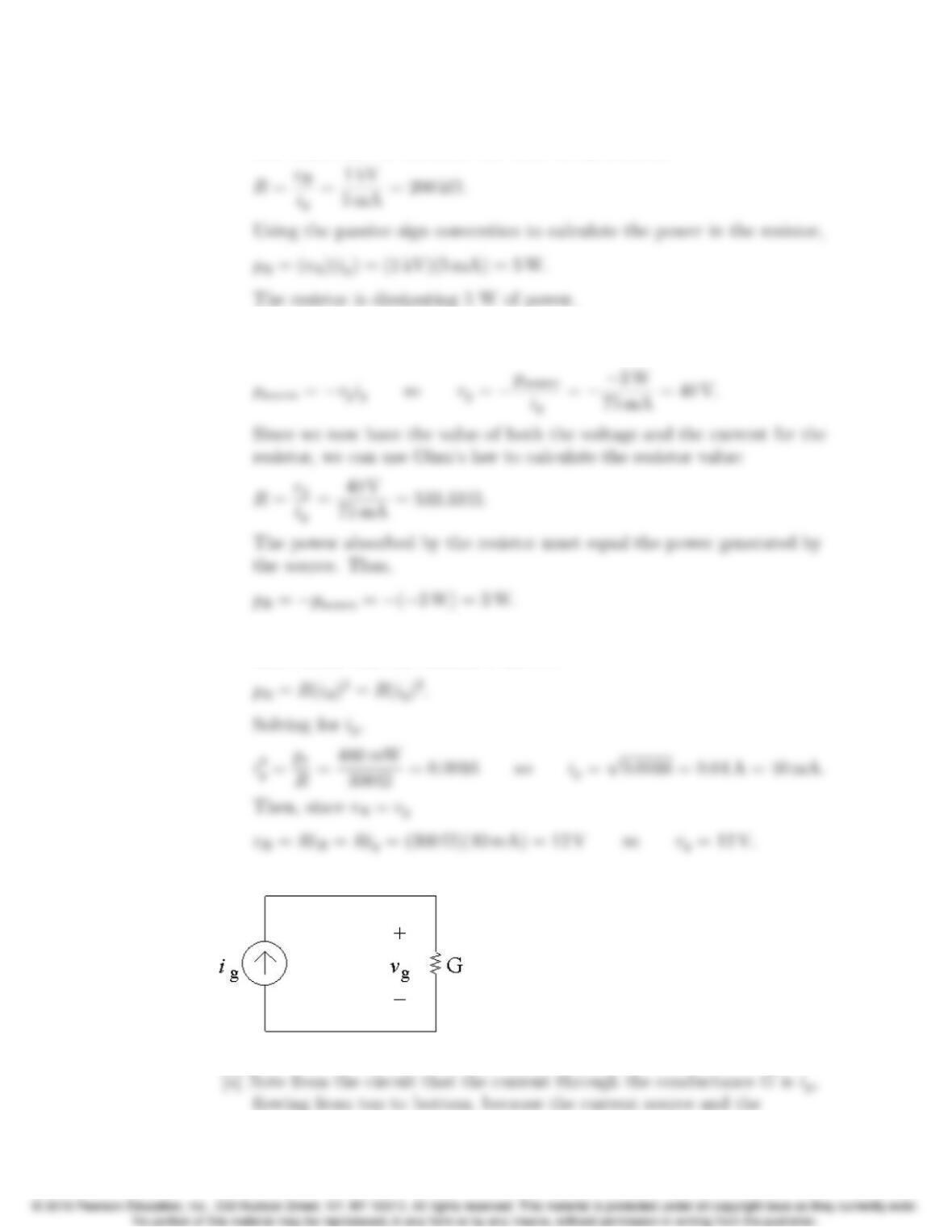
[a] The resistor and the voltage source are in parallel and the resistor voltage
Problems 2–3
Note from the circuit that the current through the resistor is ig= 5 mA.
Use Ohm’s law to calculate the value of the resistor:
[b] Note from part (a) the vR=vgand iR=ig. The power delivered by the
source is thus
[c] Again, note the iR=ig. The power dissipated by the resistor can be
determined from the resistor’s current:
AP 2.4
2–4 CHAPTER 2. Circuit Elements
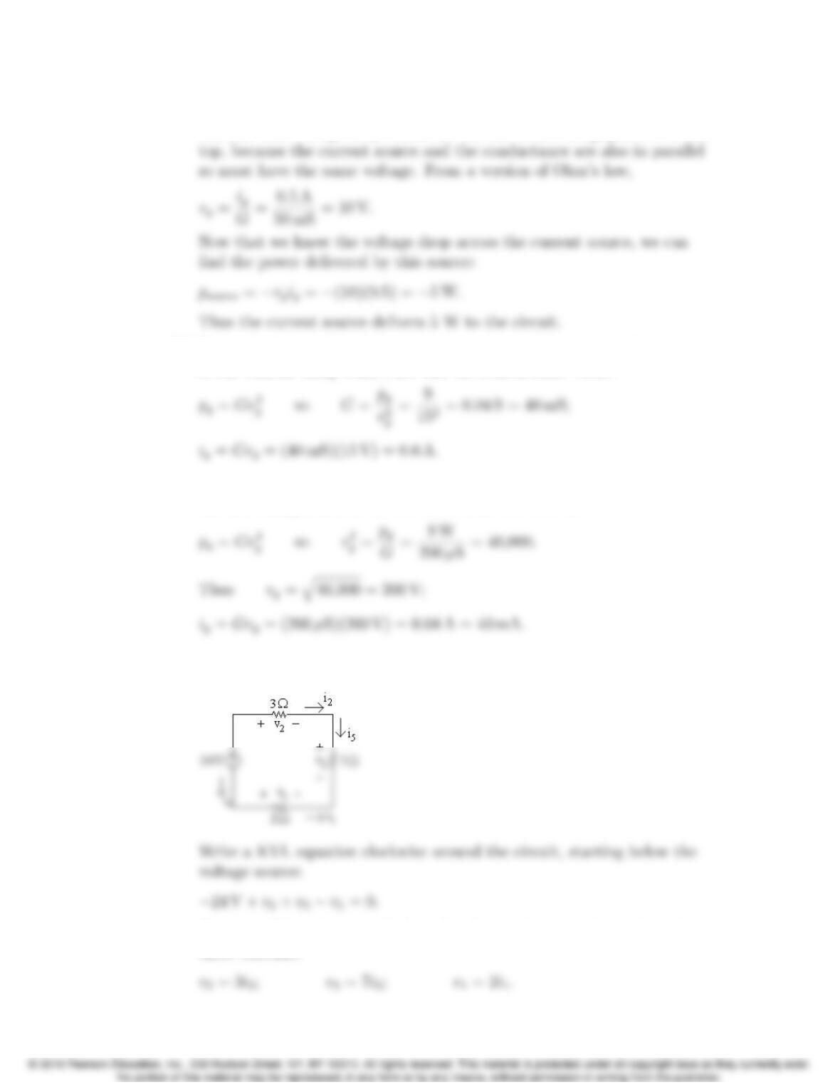
conductance are in the same branch of the circuit so must have the same
current. The voltage drop across the current source is vg, positive at the
[b] We can find the value of the conductance using the power, and the value
of the current using Ohm’s law and the conductance value:
[c] We can find the voltage from the power and the conductance, and then
use the voltage value in Ohm’s law to find the current:
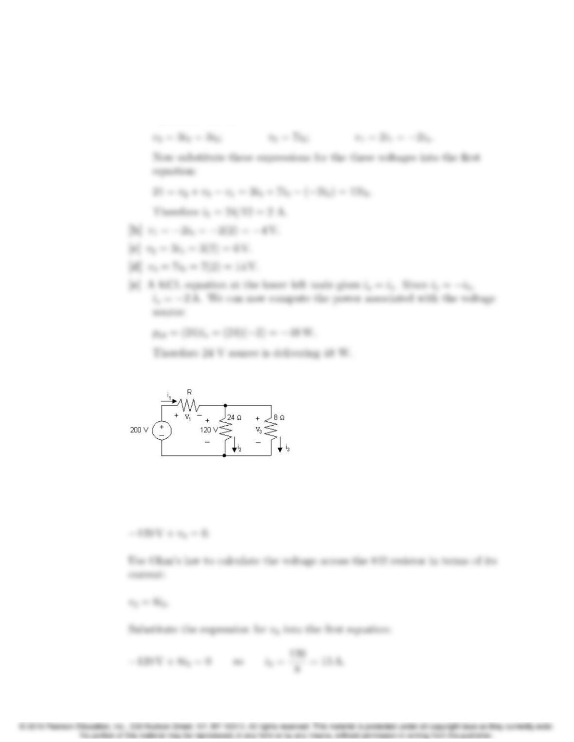
AP 2.5 [a] Redraw the circuit with all of the voltages and currents labeled for every
circuit element.
Next, use Ohm’s law to calculate the three unknown voltages from the
three currents:
Problems 2–5
A KCL equation at the upper right node gives i2=i5; a KCL equation at
the bottom right node gives i5=−i1; a KCL equation at the upper left
node gives is=−i2. Now replace the currents i1and i2in the Ohm’s law
equations with i5:
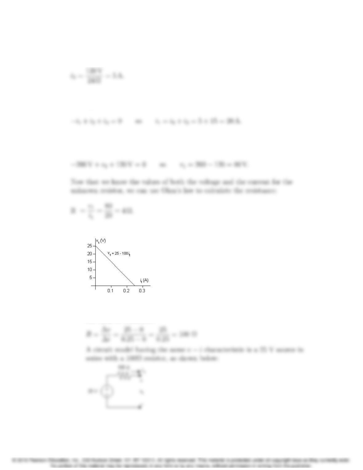
AP 2.6 Redraw the circuit labeling all voltages and currents:
We can find the value of the unknown resistor if we can find the value of its
voltage and its current. To start, write a KVL equation clockwise around the
right loop, starting below the 24 Ωresistor:
2–6 CHAPTER 2. Circuit Elements
Also use Ohm’s law to calculate the value of the current through the 24 Ω
resistor:
Now write a KCL equation at the top middle node, summing the currents
leaving:
Write a KVL equation clockwise around the left loop, starting below the
voltage source:
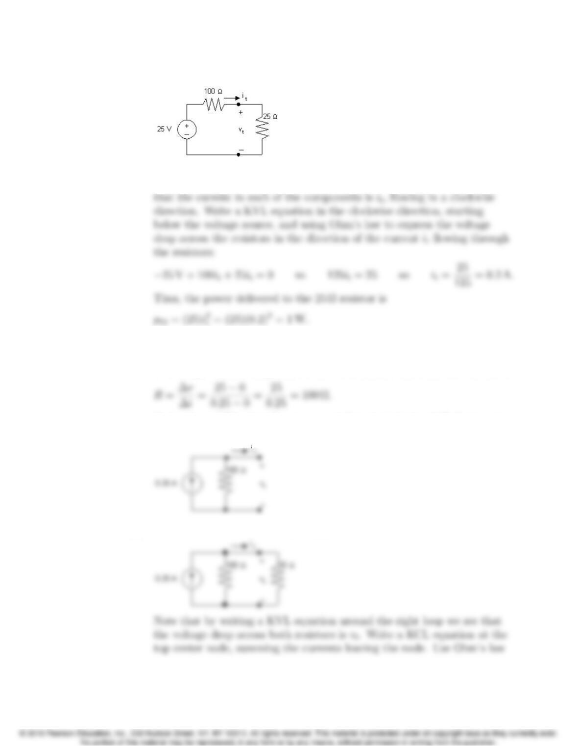
AP 2.7 [a] Plotting a graph of vtversus itgives
Note that when it= 0, vt= 25 V; therefore the voltage source must be
25 V. Since the plot is a straight line, its slope can be used to calculate
the value of resistance:
Problems 2–7
[b] Draw the circuit model from part (a) and attach a 25 Ωresistor:
To find the power delivered to the 25 Ωresistor we must calculate the
current through the 25 Ωresistor. Do this by first using KCL to recognize
AP 2.8 [a] From the graph in Assessment Problem 2.7(a), we see that when vt= 0,
it=0.25 A. Therefore the current source must be 0.25 A. Since the plot
is a straight line, its slope can be used to calculate the value of resistance:
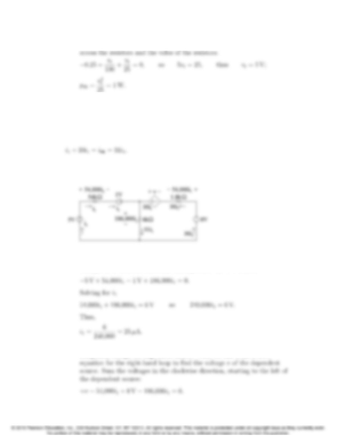
A circuit model having the same v−icharacteristic is a 0.25 A current
source in parallel with a 100Ωresistor, as shown below:
[b] Draw the circuit model from part (a) and attach a 25 Ωresistor:
2–8 CHAPTER 2. Circuit Elements
to specify the currents through the resistors in terms of the voltage drop
AP 2.9 First note that we know the current through all elements in the circuit except
the 6 kΩresistor (the current in the three elements to the left of the 6 kΩ
resistor is i1; the current in the three elements to the right of the 6 kΩresistor
is 30i1). To find the current in the 6 kΩresistor, write a KCL equation at the
top node:
We can then use Ohm’s law to find the voltages across each resistor in terms
of i1. The results are shown in the figure below:
[a] To find i1, write a KVL equation around the left-hand loop, summing
voltages in a clockwise direction starting below the 5 V source:
[b] Now that we have the value of i1, we can calculate the voltage for each
component except the dependent source. Then we can write a KVL
Problems 2–9
Thus,
We now know the values of voltage and current for every circuit element.
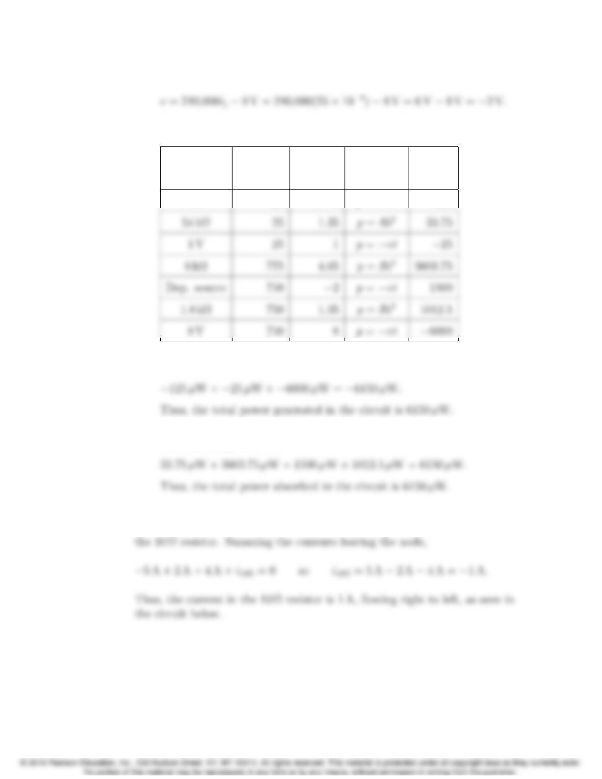
Let’s construct a power table:
Element Current Voltage Power Power
(µA) (V) Equation (µW)
5V 25 5 p=−vi −125
[c] The total power generated in the circuit is the sum of the negative power
values in the power table:
[d] The total power absorbed in the circuit is the sum of the positive power
values in the power table:
AP 2.10 Given that iφ= 2 A, we know the current in the dependent source is
2iφ= 4 A. We can write a KCL equation at the left node to find the current in
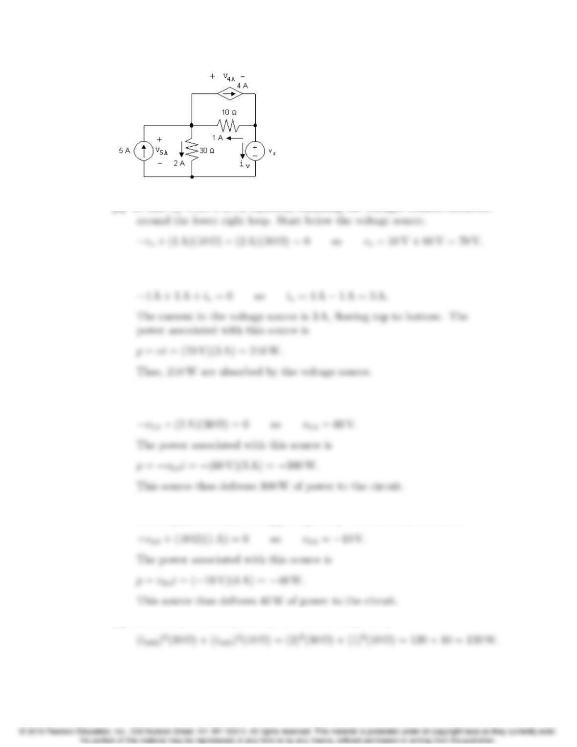
2–10 CHAPTER 2. Circuit Elements
[a] To find vs, write a KVL equation, summing the voltages counter-clockwise
[b] The current in the voltage source can be found by writing a KCL equation
at the right-hand node. Sum the currents leaving the node
[c] The voltage drop across the independent current source can be found by
writing a KVL equation around the left loop in a clockwise direction:
[d] The voltage across the controlled current source can be found by writing a
KVL equation around the upper right loop in a clockwise direction:
[e] The total power dissipated by the resistors is given by
Problems 2–11
Problems
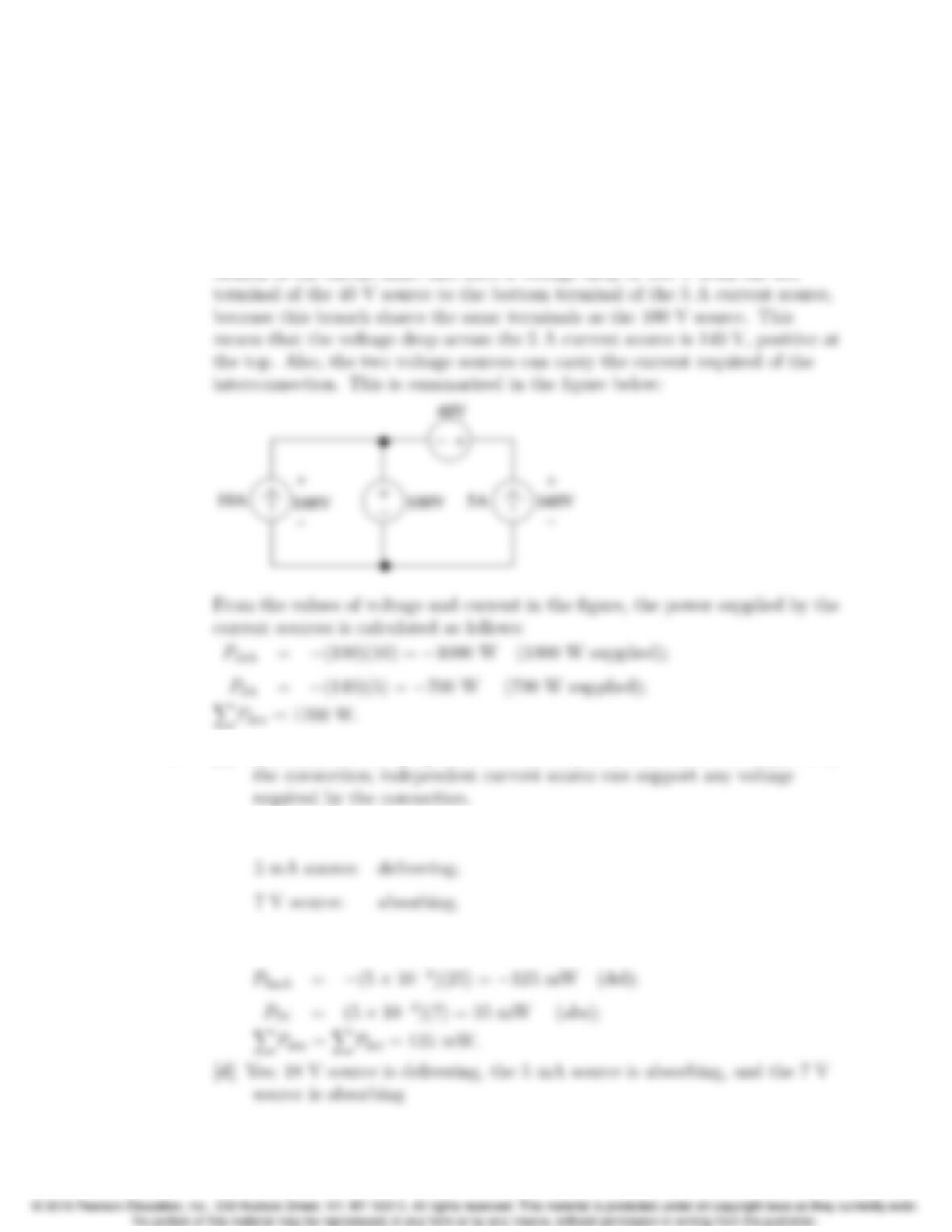
P 2.1 The interconnection is valid. The 10 A current source has a voltage drop of
100 V, positive at the top, because the 100 V source supplies its voltage drop
across a pair of terminals shared by the 10 A current source. The right hand
P 2.2 [a] Yes, independent voltage sources can carry whatever current is required by
[b] 18 V source: absorbing;
[c] P18V =(5×10⁻³)(18) = 90 mW (abs);
2–12 CHAPTER 2. Circuit Elements
P18V =−(5 ×10⁻³)(18) = −90 mW (del);
P 2.3 The interconnection is not valid. Note that the 3 A and 4 A sources are both
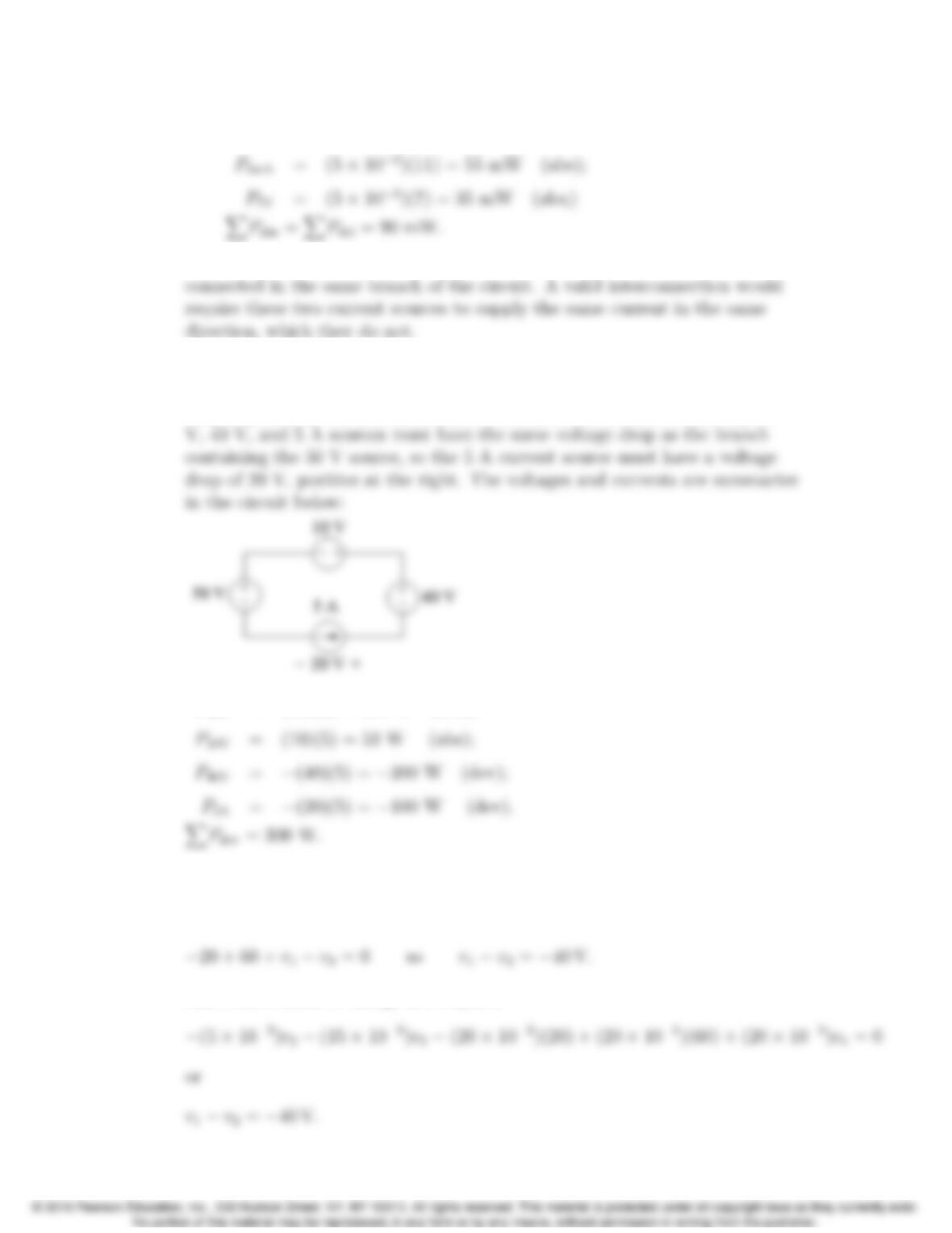
P 2.4 The interconnect is valid since the voltage sources can all carry 5 A of current
supplied by the current source, and the current source can carry the voltage
drop required by the interconnection. Note that the branch containing the 10
P50V = (50)(5) = 250 W (abs);
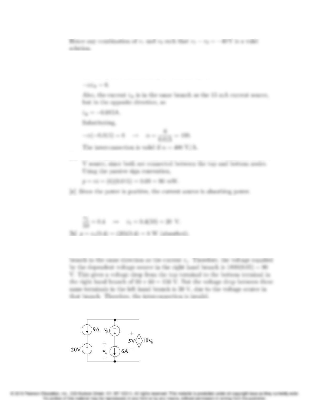
P 2.5 First there is no violation of Kirchhoff’s laws, hence the interconnection is
valid.
Kirchhoff’s voltage law requires
The conservation of energy law requires
Problems 2–13
P 2.6 [a] The voltage drop from the top node to the bottom node in this circuit
must be the same for every path from the top to the bottom. Therefore,
the voltages of the two voltage sources are equal:
[b] The voltage across the current source must equal the voltage across the 6
P 2.7 [a] Because both current sources are in the same branch of the circuit, their
values must be the same. Therefore,
P 2.8 The interconnection is invalid. In the middle branch, the value of the current
ixmust be 50 mA, since the 50 mA current source supplies current in this
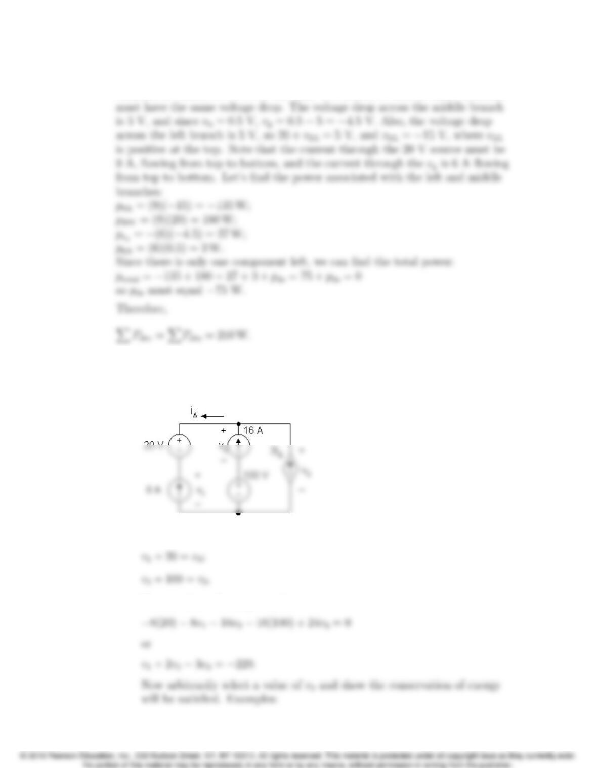
P 2.9
2–14 CHAPTER 2. Circuit Elements
First, 10va= 5 V, so va=0.5 V. Then recognize that each of the three
branches is connected between the same two nodes, so each of these branches
P 2.10 [a] Yes, Kirchhoff’s laws are not violated. (Note that i∆=−8 A.)
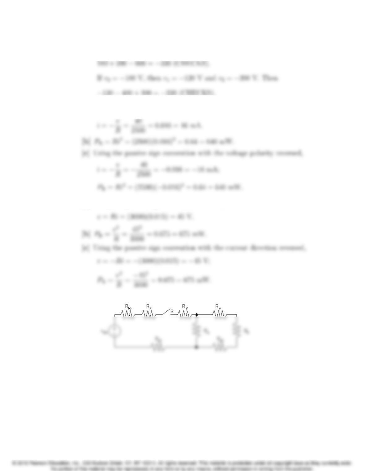
[b] No, because the voltages across the independent and dependent current
sources are indeterminate. For example, define v1,v2, and v3as shown:
Kirchhoff’s voltage law requires
Conservation of energy requires
Problems 2–15
If v3= 200 V then v1= 180 V and v2= 100 V. Then
P 2.11 [a] Using the passive sign convention and Ohm’s law,
P 2.12 [a] Using the passive sign convention and Ohm’s law,
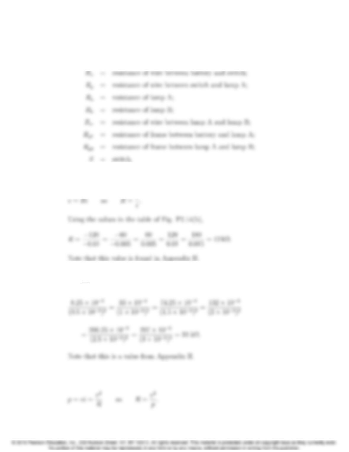
P 2.13 [a]
2–16 CHAPTER 2. Circuit Elements
[b] Vbb = no-load voltage of battery;
Rbb = internal resistance of battery;
P 2.14 Since we know the device is a resistor, we can use Ohm’s law to calculate the
resistance. From Fig. P2.14(a),
P 2.15 The resistor value is the ratio of the power to the square of the current:
R=p
i2. Using the values for power and current in Fig. P2.15(b),
P 2.16 Since we know the device is a resistor, we can use the power equation. From
Fig. P2.16(a),
Problems 2–17
Using the values in the table of Fig. P2.16(b)
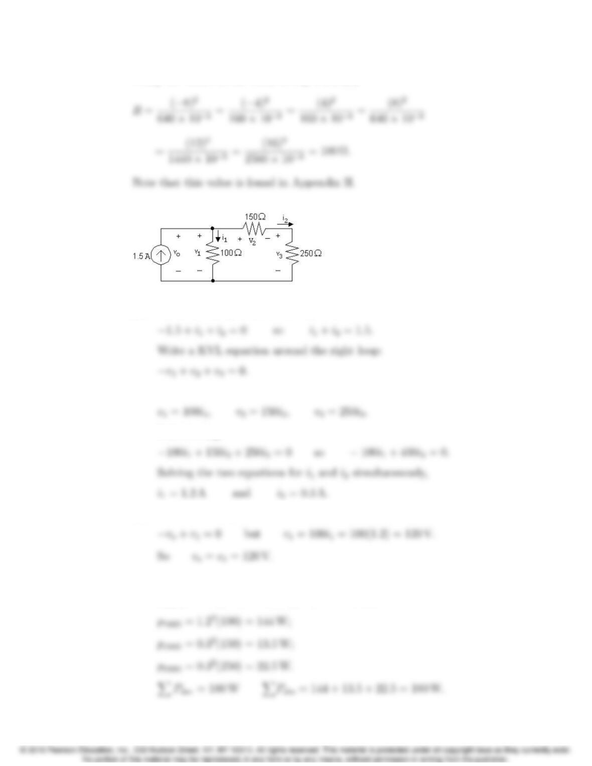
P 2.17
[a] Write a KCL equation at the top node:
From Ohm’s law,
Substituting,
[b] Write a KVL equation clockwise around the left loop:
[c] Calculate power using p=vi for the source and p=Ri2for the resistors:
psource =−vo(1.5) = −(120)(1.5) = −180 W;
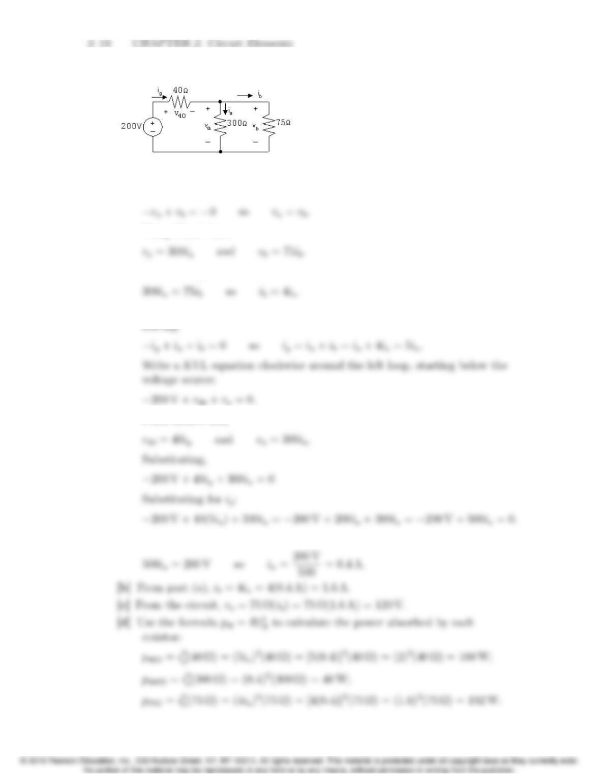
P 2.18
[a] Write a KVL equation clockwise aroud the right loop, starting below the
300 Ωresistor:
Using Ohm’s law,
Substituting,
Write a KCL equation at the top middle node, summing the currents
From Ohm’s law,
Thus,
Problems 2–19
[e] Using the passive sign convention,
P 2.19 [a] vo=8ia+14ia+18ia= 40(20) = 800 V;
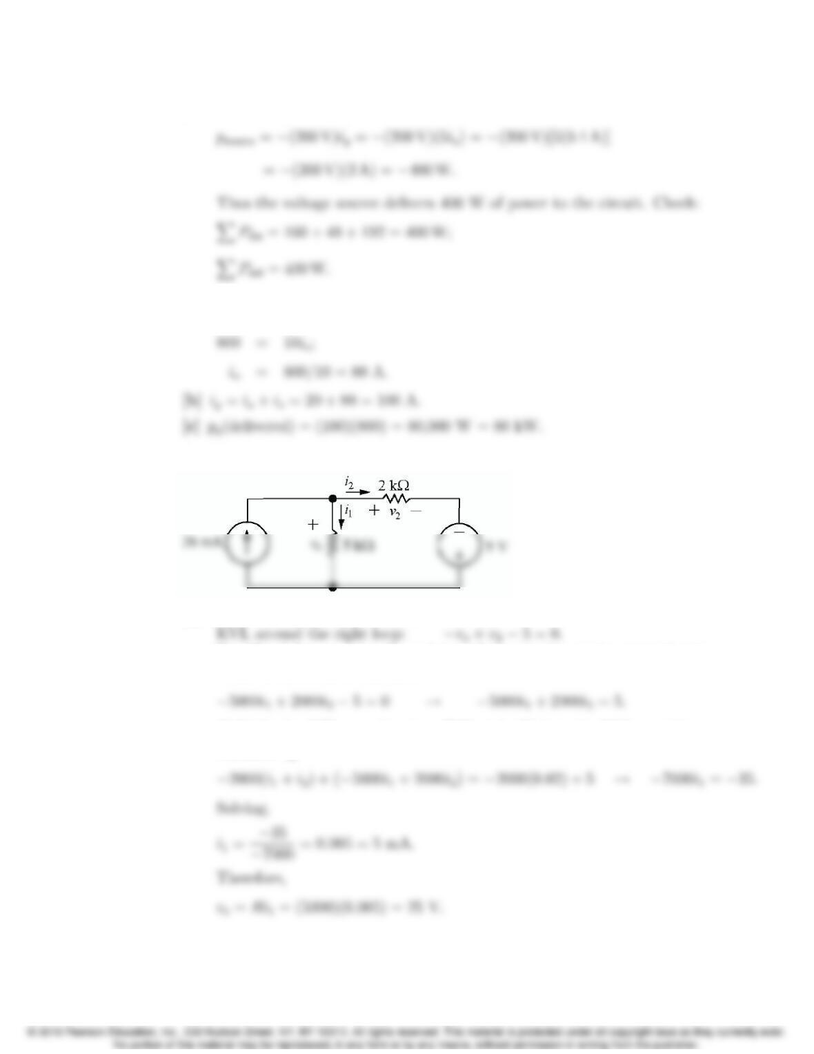
P 2.20 Label the unknown resistor currents and voltages:
[a] KCL at the top node: 0.02 = i1+i2;
Use Ohm’s law to write the resistor voltages in the previous equation in
terms of the resistor currents:
Multiply the KCL equation by −2000 and add it to the KVL equation to
eliminate i2: