On the other hand, for
t
LRR
9
, we have
P2.95* To maximize the power to
L
R
, we must maximize the voltage across it.
Thus, we need to have
0
t
R
. The maximum power is
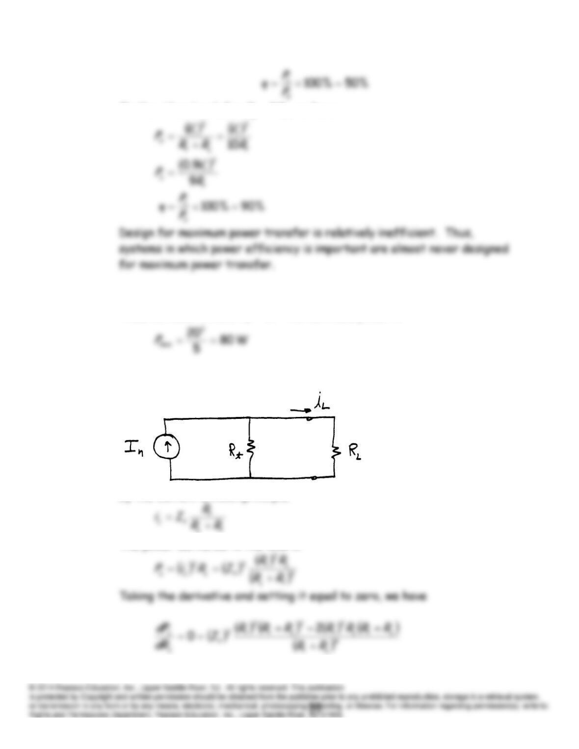
P2.96 The circuit is
By the current division principle:
The power delivered to the load is
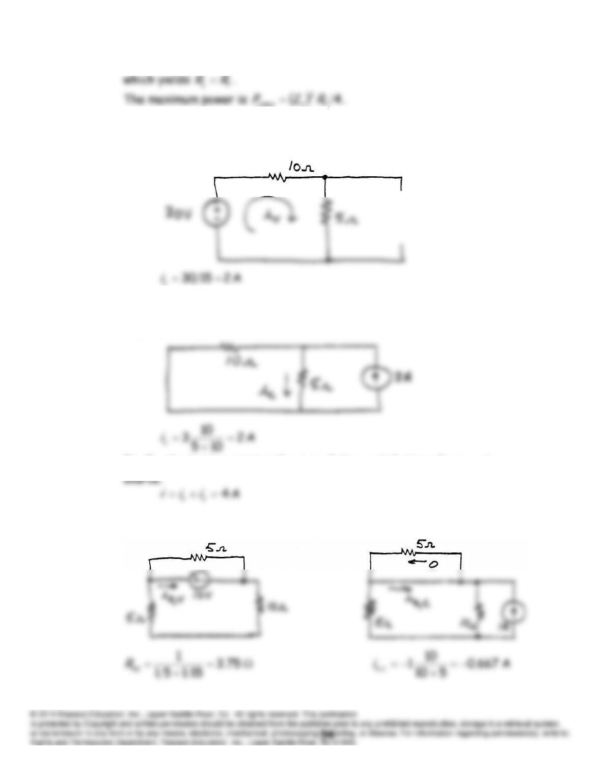
P2.97* First, we zero the current source and find the current due to the voltage
source.
Then, we zero the voltage source and use the current-division principle to
find the current due to the current source.
Finally, the total current is the sum of the contributions from each
P2.98* The circuits with only one source active at a time are:
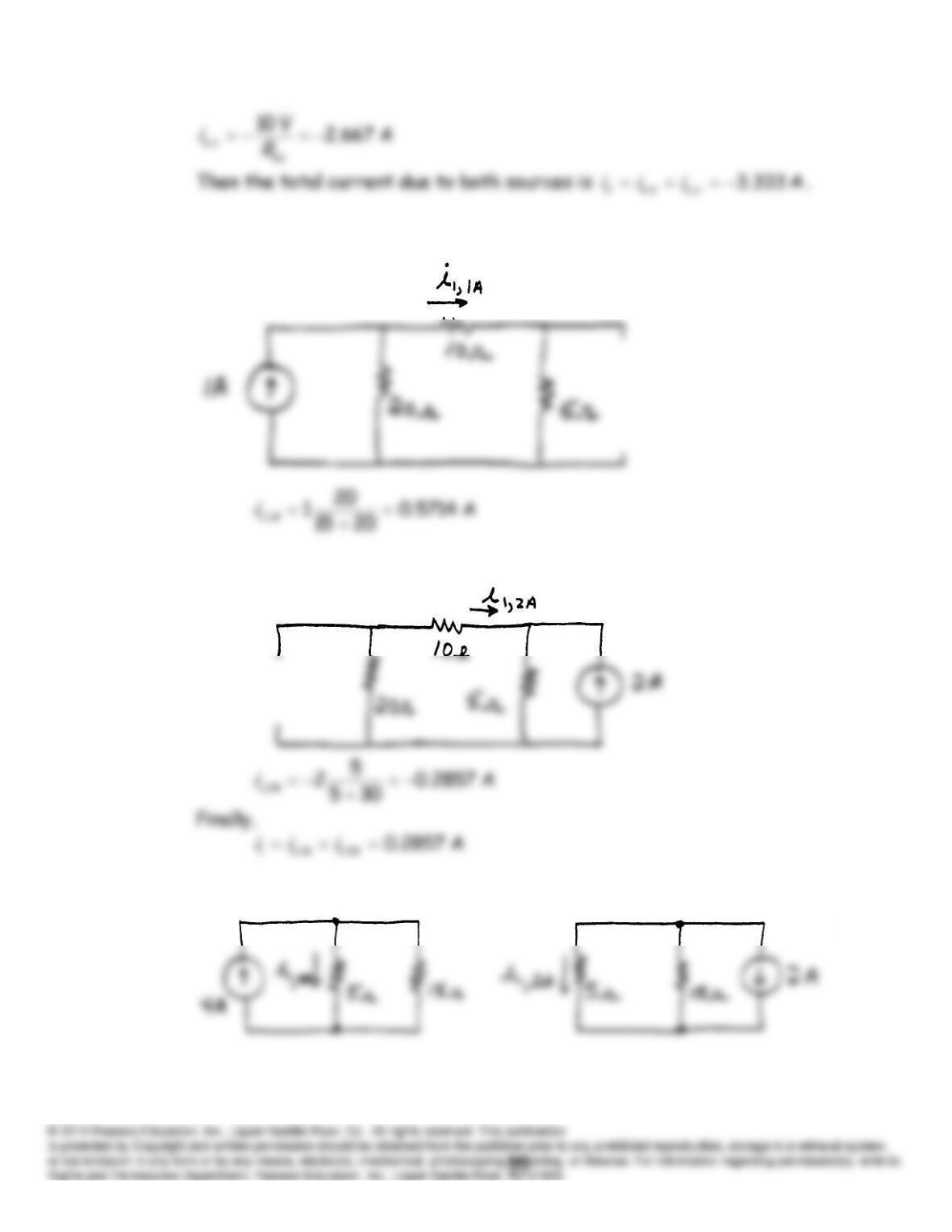
P2.99 Zero the 2-A source and use the current-division principle:
Then zero the 1 A source and use the current-division principle:
P2.100 The circuits with only one source active at a time are:
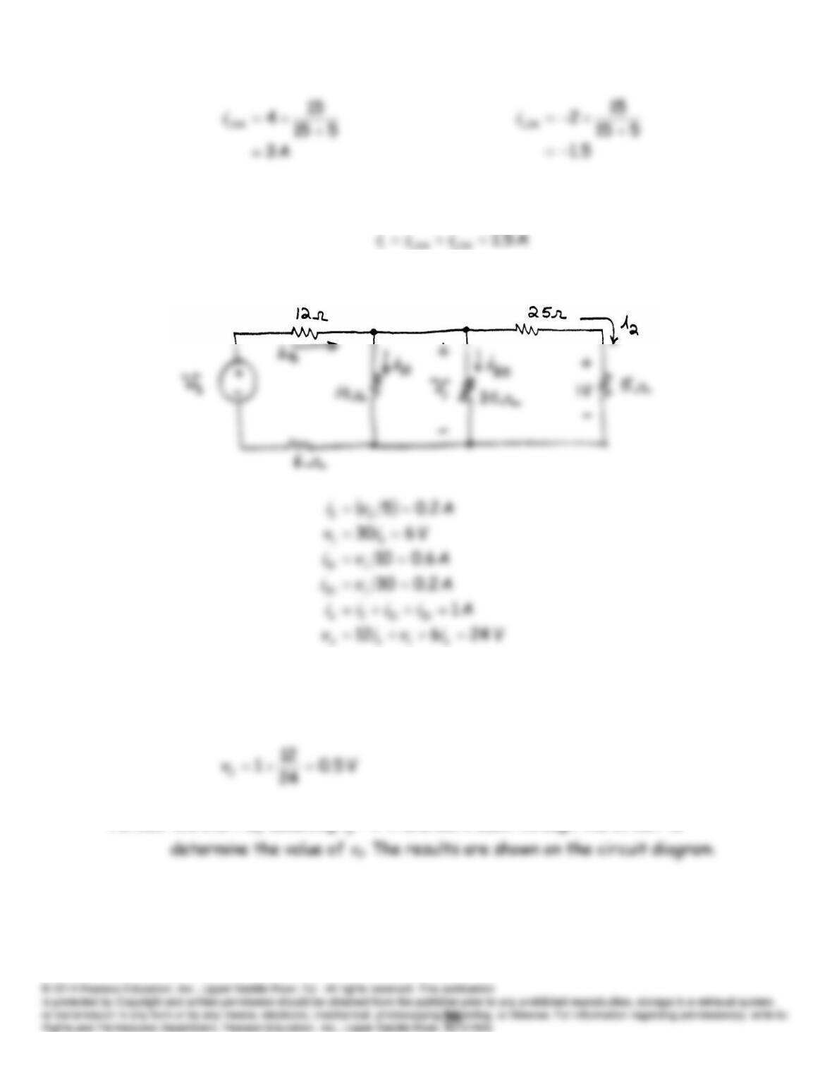
Finally, we add the components to find the current with both sources
active.
P2.101 The circuit, assuming that
V 1
2
v
is:
We have established that for
V 24
s
v
, we have
V 1
2
v
. Thus, for
V 12
s
v
, we have:
P2.102 We start by assuming
1
i
A and work back through the circuit to
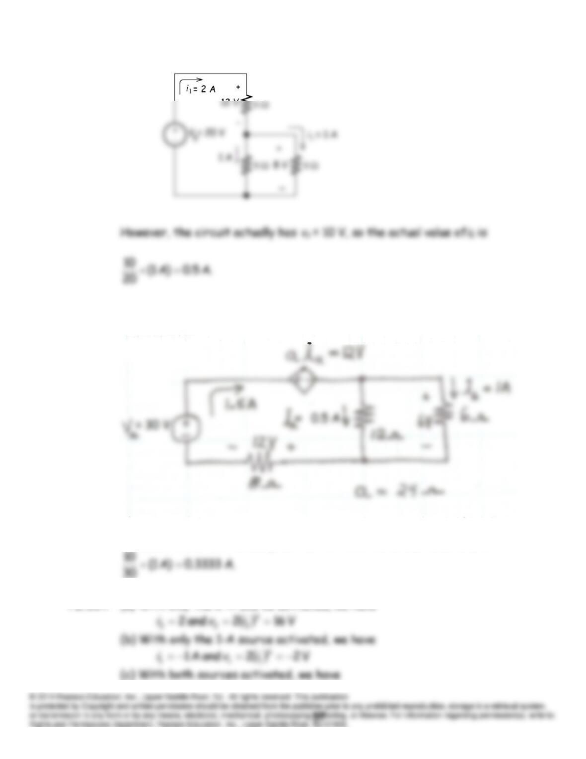
P2.103 We start by assuming
1
6
i
A and work back through the circuit to
determine the value of
Vs
. This results in
Vs
30 V.
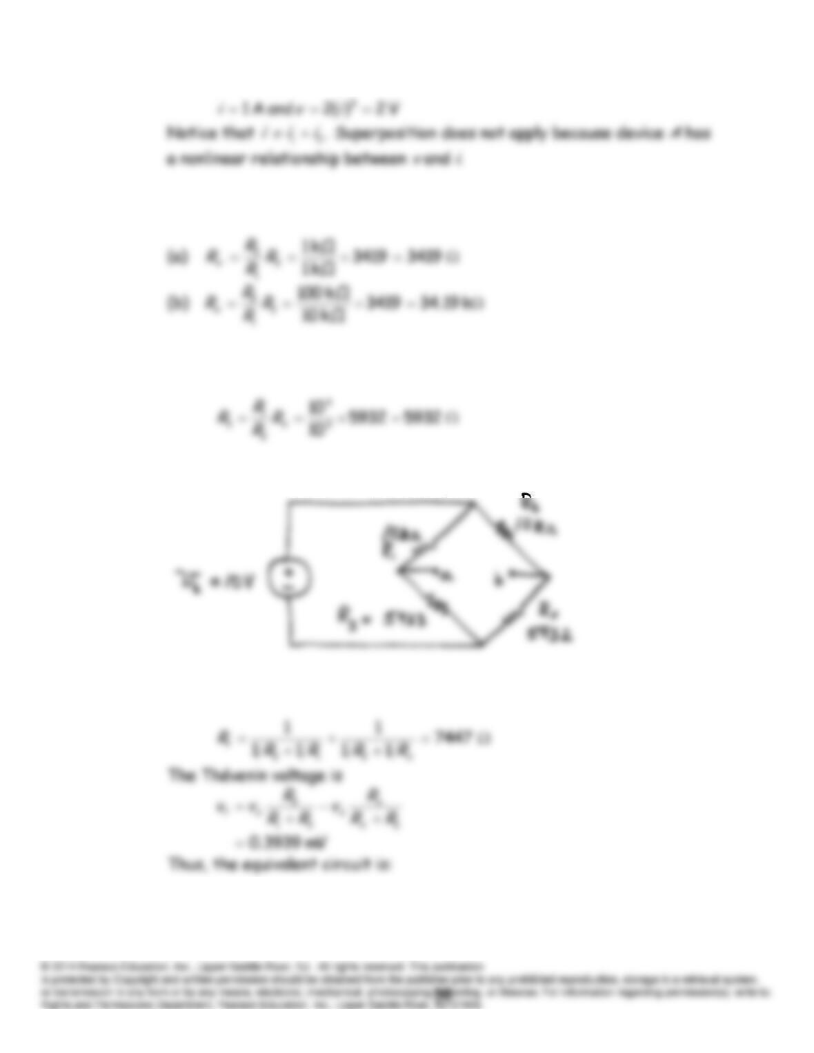
However, the circuit actually has
Vs
= 10 V, so the actual value of
i
6
is
P2.104 (a) With only the 2-A source activated, we have
P2.105 From Equation 2.91, we have
P2.106* (a) Rearranging Equation 2.91, we have
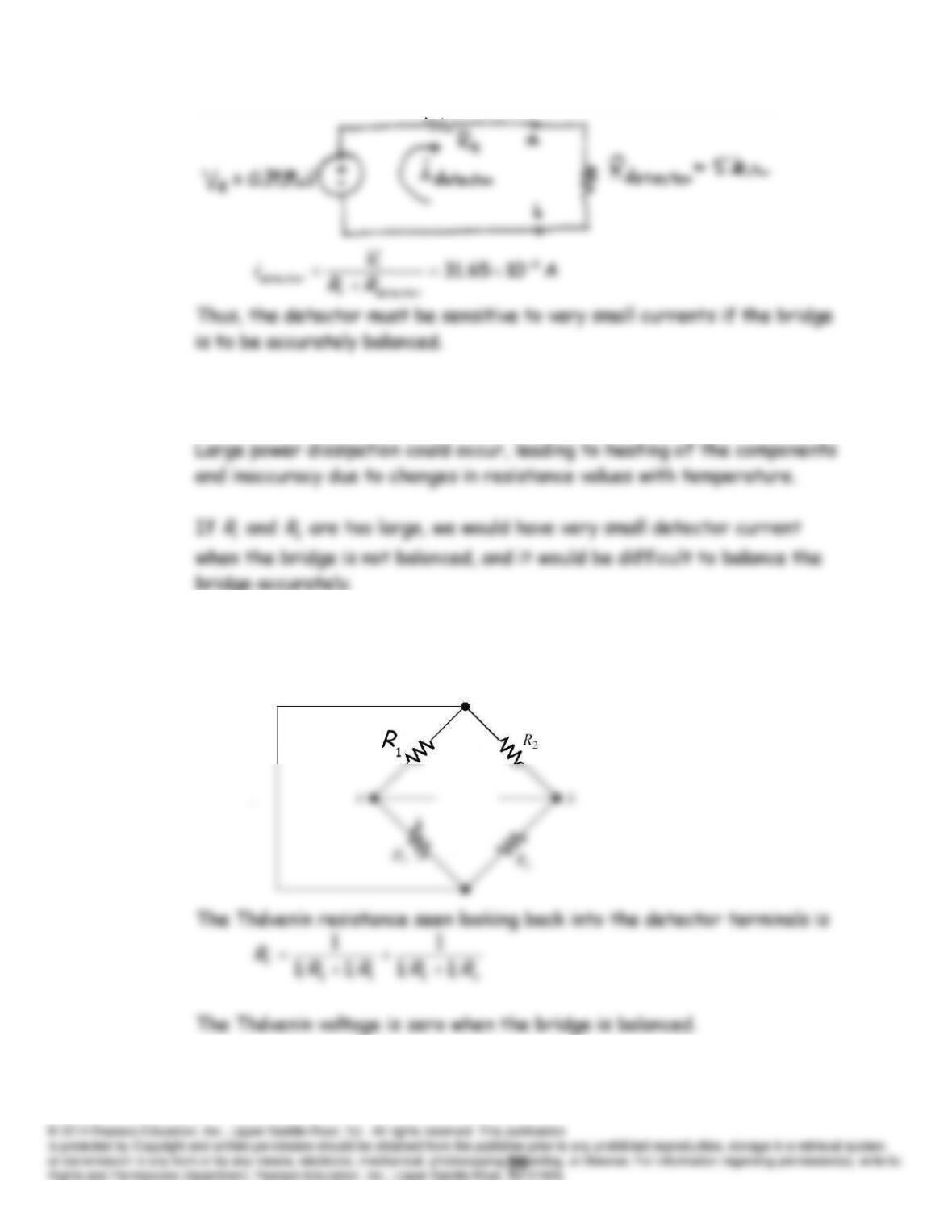
(b) The circuit is:
The Thévenin resistance is
P2.107 If
1
R
and
3
R
are too small, large currents are drawn from the source. If
the source were a battery, it would need to be replaced frequently.
1
3
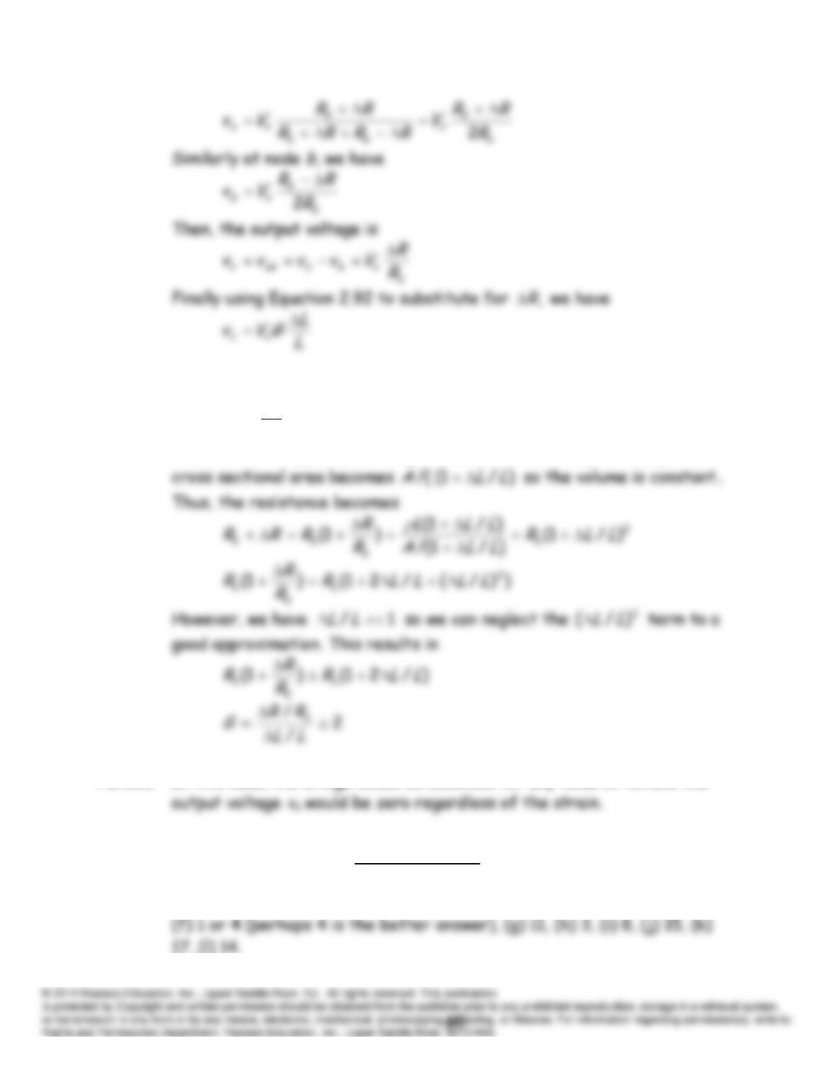
P2.108 With the source replaced by a short circuit and the detector removed,
the Wheatstone bridge circuit becomes
P2.109 Using the voltage-division principle, the voltage at node
a
is
P2.110 Before strain is applied, the resistance is
A
L
R
0
After strain is applied, the length becomes
),/1(
LLLLL
and the
P2.111 In this case, the bridge would be balanced for any value of
R
and the
Practice Test
T2.1 (a) 6, (b) 10, (c) 2, (d) 7, (e) 10 or 13 (perhaps 13 is the better answer),
T2.2 The equivalent resistance seen by the voltage source is:
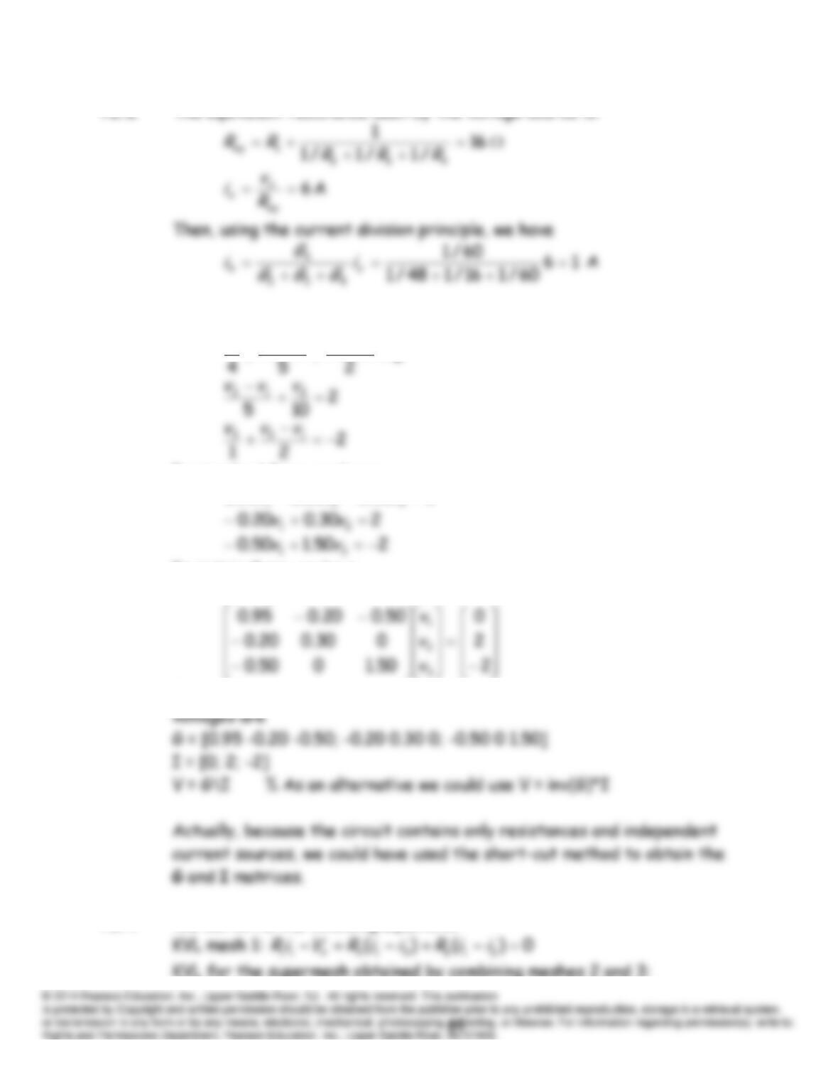
T2.3 Writing KCL equations at each node gives
0
31
211
vv
vvv
In standard form, we have:
050.020.095.0 321
vvv
In matrix form, we have
GV I
The MATLAB commands needed to obtain the column vector of the node
T2.4 We can write the following equations:
KVL for the supermesh obtained by combining meshes 2 and 3:
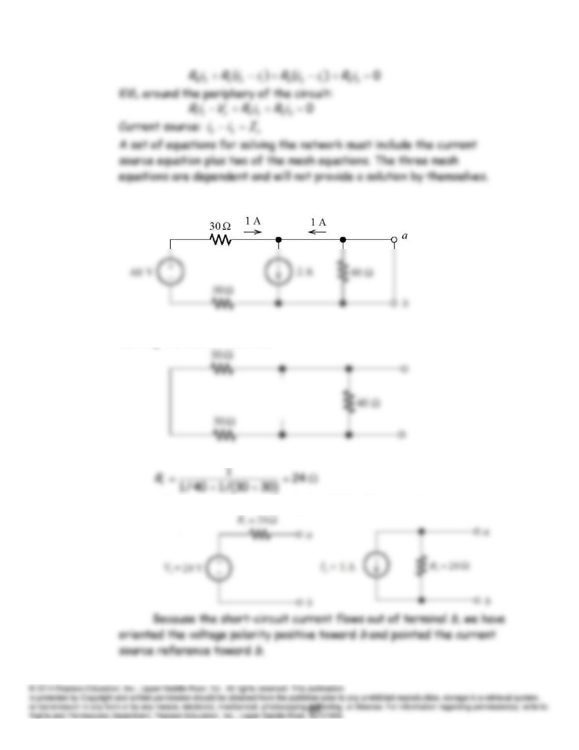
T2.5 Under short-circuit conditions, the circuit becomes
Thus, the short-circuit current is 1 A flowing out of
b
and into
a
.
Zeroing the sources, we have
Thus, the Thévenin resistance is
and the Thévenin voltage is
V 24
tsctRIV
. The equivalent circuits are:
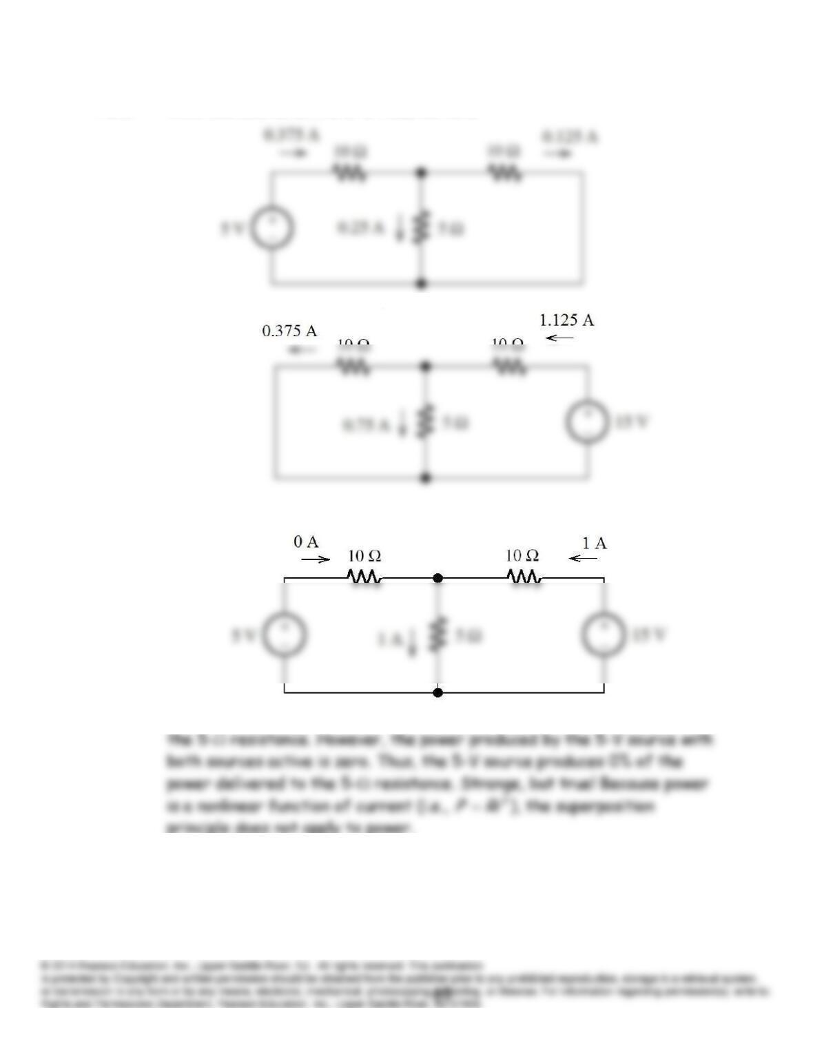
T2.6 With one source active at a time, we have
Then, with both sources active, we have
We see that the 5-V source produces 25% of the total current through