18–32 CHAPTER 18. Two-Port Circuits
P 18.35 When V2=0
V1= 20 V,I
1=1A,I
2=−1A.
h11 =V1
I1V2=0
=20
1= 20 Ω;
Source-transform the current source and parallel resistance to get Vg= 240 V.
Then,
Problems 18–33
P 18.36 [a] V1=z11I1+z12I2;
V2=z21I1+z22I2;
[b] V2
Vg
=z21ZL
(z11 +Zg)(z22 +ZL)−z12z21
=z21
(z11 + 1)(z22 +1)−z12z21
s1,2=−1
2±j√7
2;
18–34 CHAPTER 18. Two-Port Circuits
CHECK
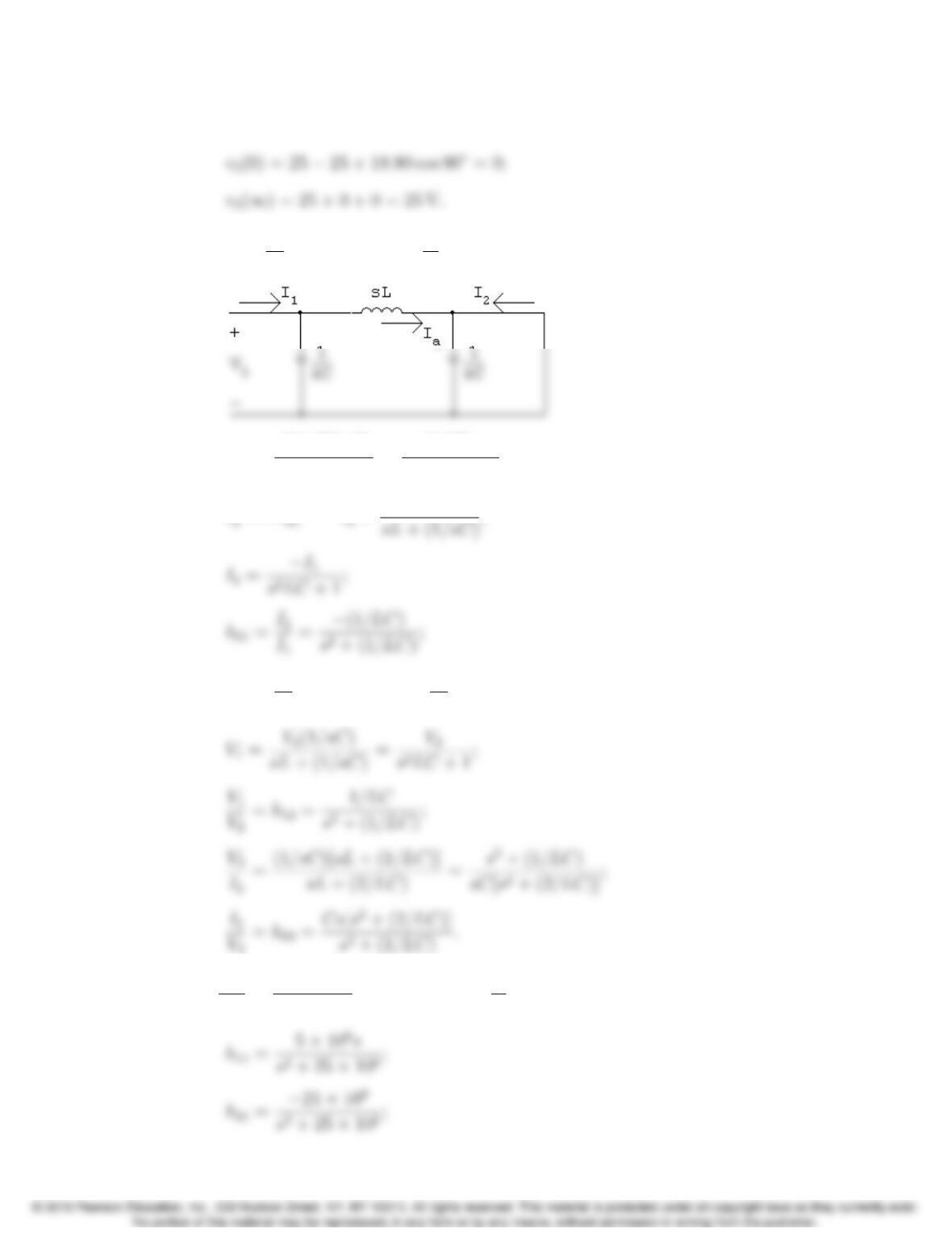
P 18.37 [a] h11 =V1
I1V2=0
;h21 =I2
I1V2=0
.
h11 =(1/sC)(sL)
(1/sC)+sL =(1/C)s
s2+ (1/LC);
I2=−Ia;Ia=I1(1/sC)
h12 =V1
V2I1=0
;h22 =I2
V2I1=0
.
[b] 1
LC =(103)(106)
(0.2)(200) = 25 ×106;1
C=5×10⁶;
Problems 18–35
V2
V1
=−h21ZL
∆hZL+h11
.
∆h= 1 (the circuit is reciprocal and symmetrical).
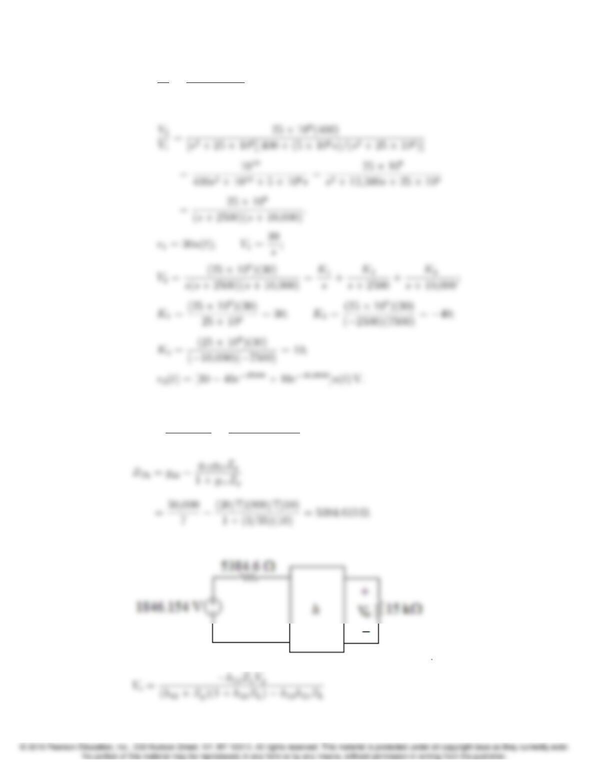
P 18.38 The Thevenin equivalent seen looking into the g-network from the right is
VTh =g21Vg
1+g11Zg
=(800/7)(30)
1+(3/35)(10) = 1846.154 V;
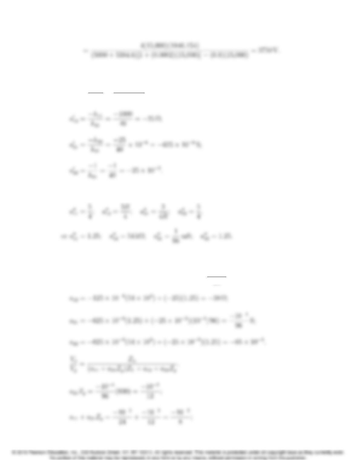
The simplified circuit is shown here:
18–36 CHAPTER 18. Two-Port Circuits
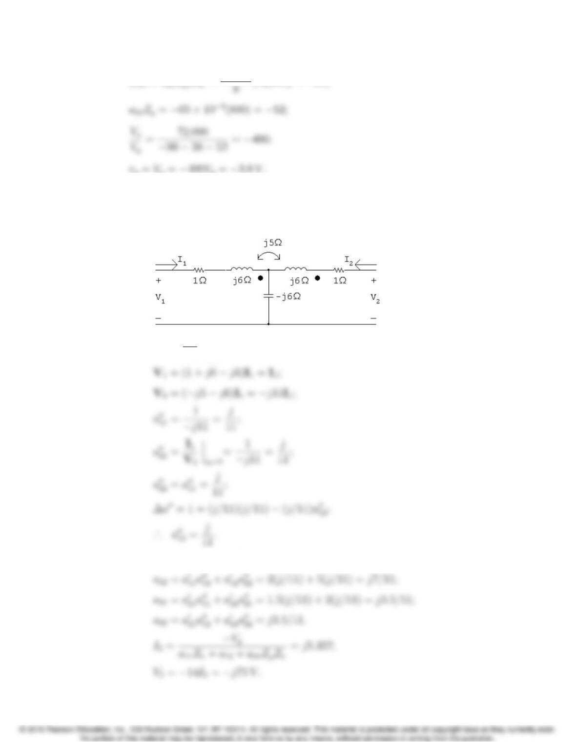
P 18.39 The aparameters of the first two port are
a0
11 =−∆h
h21
=−5×10³
40 =−125 ×106;
The aparameters of the second two port are
The aparameters of the cascade connection are
a11 =−125 ×106(1.25) + (−25)(103/96) = −102
24 ;
Problems 18–37
(a11 +a21Zg)ZL=−102
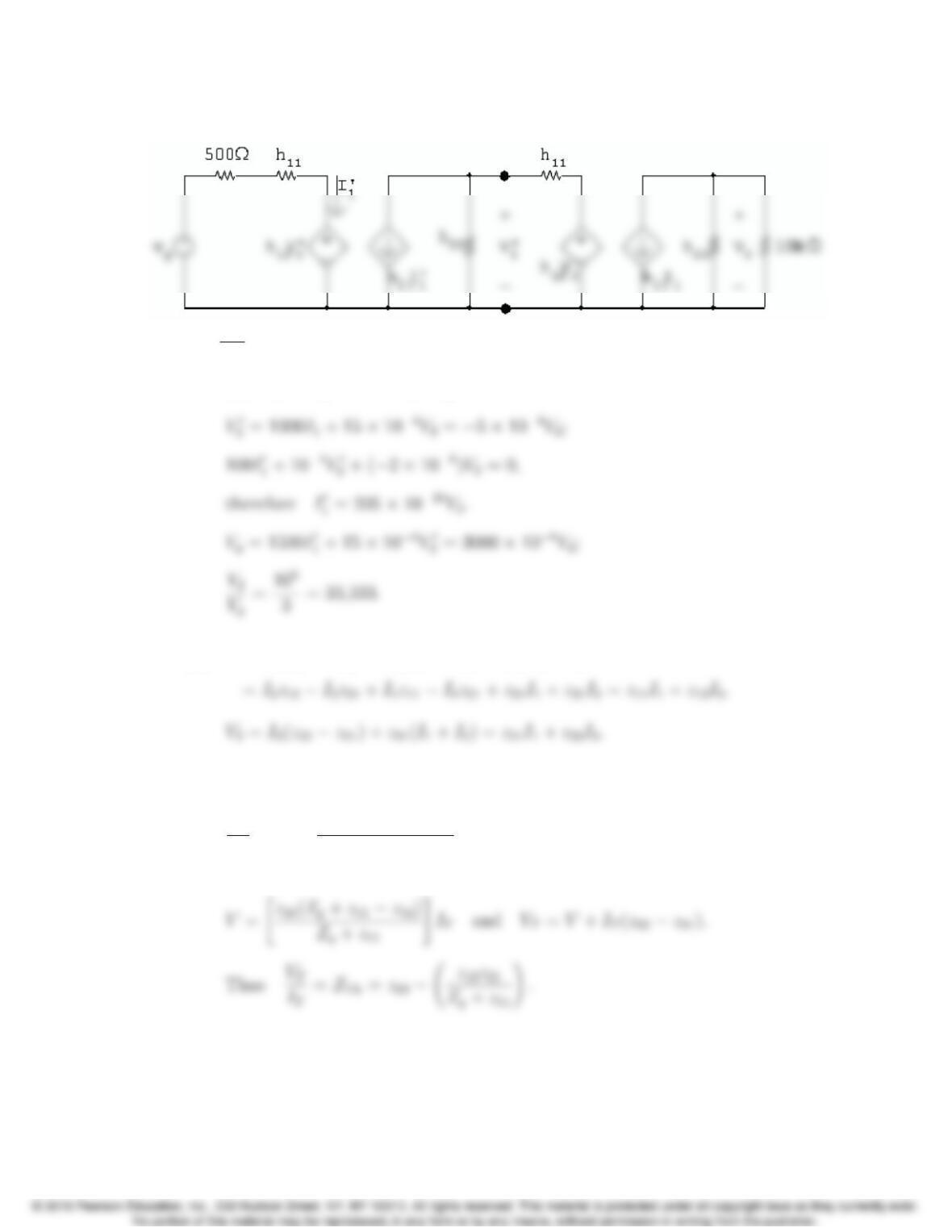
P 18.40 [a] From reciprocity and symmetry
a0
11 =a0
22,∆a0= 1; ·
.. 4−2a0
21 =1,a
0
21 =1.5S.
For network B
a00
11 =V1
V2I2=0
;
[b] a11 =a0
11a00
11 +a0
12a00
21 = 2(j/11) + 5(j/11) = j7/11;
18–38 CHAPTER 18. Two-Port Circuits
P 18.41 [a] At the input port: V1=h11I1+h12V2;
At the output port: I2=h21I1+h22V2.
[b] V2
104+ (100 ×106V2) + 100I1=0,
therefore I1=−2×10⁶V2.
P 18.42 [a] V1=I2(z12 −z21)+I1(z11 −z21)+z21(I1+I2)
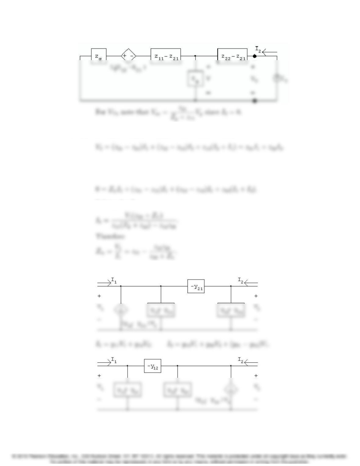
[b] Short circuit Vgand apply a test current source to port 2 as shown. Note
that IT=I2.We have
V
z21 −IT+V+IT(z12 −z21)
Zg+z11 −z21
=0.
Therefore
Problems 18–39
P 18.43 [a] V1=(z11 −z12)I1+z12(I1+I2)=z11I1+z12I2;
[b] With port 2 terminated in an impedance ZL,the two mesh equations are
V1=(z11 −z12)I1+z12(I1+I2);
Solving for I1:
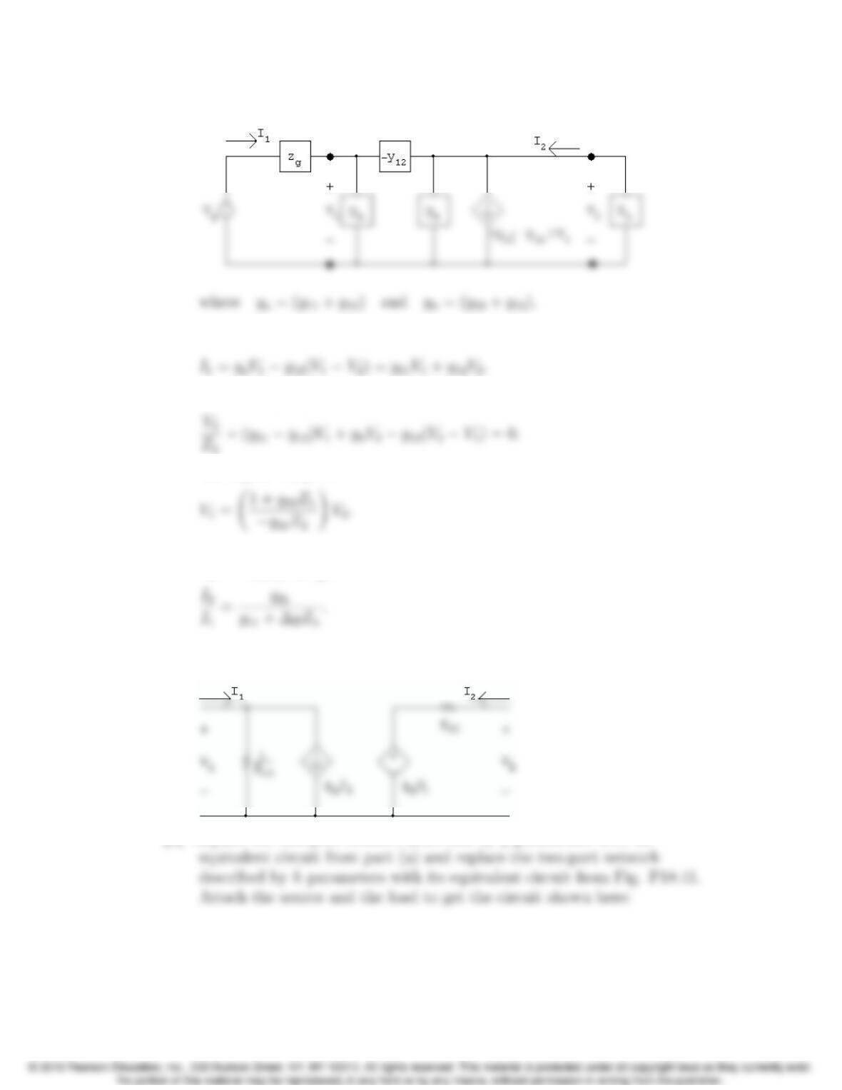
P 18.44 [a] I1=y11V1+y21V2+(y12 −y21)V2;I2=y21V1+y22V2.
18–40 CHAPTER 18. Two-Port Circuits
[b] Using the second circuit derived in part [a], we have
At the input port we have
At the output port we have
Solving for V1gives
Substituting Eq. 18.2 into Eq. 18.1 and at the same time using
V2=−ZLI2,we get
P 18.45 [a] The g-parameter equations are I1=g11V1+g12I2and V2=g21V1+g22I2.
These equations are satisfied by the following circuit:
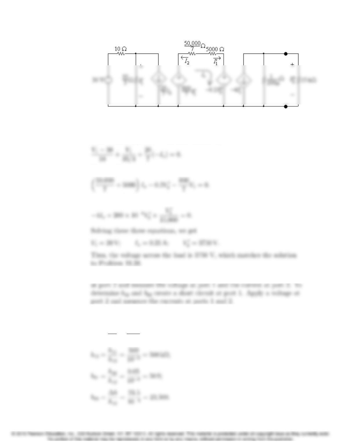
[b] Replace the two-port network described by gparameters with its
Problems 18–41
Note from the mesh in the middle of the circuit that I0
1=Ixand that
I2=−Ix.
Write a KCL equation at the node labeled V1:
Write a KVL equation for the mesh whose current is Ix:
Write a KCL equation at the node labeled V0
2:
P 18.46 [a] To determine b11 and b21 create an open circuit at port 1. Apply a voltage
[b] The equivalent b-parameters for the black-box amplifier can be calculated
as follows:
b11 =1
h12
=1
103= 1000;
18–42 CHAPTER 18. Two-Port Circuits
Create an open circuit a port 1. Apply 1 V at port 2. Then,
b11 =V2
V1I1=0
=1
V1
= 1000 so V1= 1 mV measured;
P 18.47 [a] To determine y11 and y21 create a short circuit at port 2. Apply a voltage
at port 1 and measure the currents at ports 1 and 2. To determine y12
[b] The equivalent y-parameters for the black-box amplifier can be calculated
as follows:
y11 =1
h11
=1
500 = 2 mS;
Create a short circuit at port 2. Apply 1 V at port 1. Then,
y11 =I1
V1V2=0
=I1
1= 2 mS so I1= 2 mA measured;