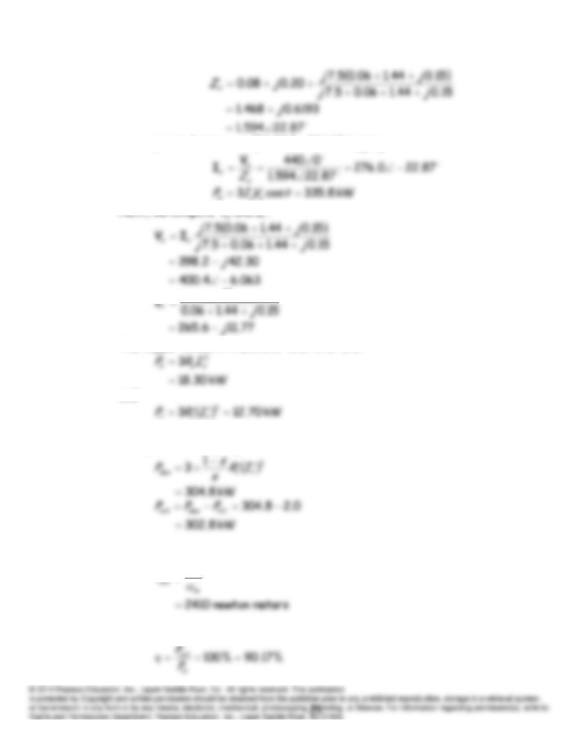
lagging %14.9287.22cosfactor power
Next, we compute
IV
and
.
x
The copper losses in the stator and rotor are:
and
Finally, the developed power is:
The output torque is:
P
T
out
The efficiency is:
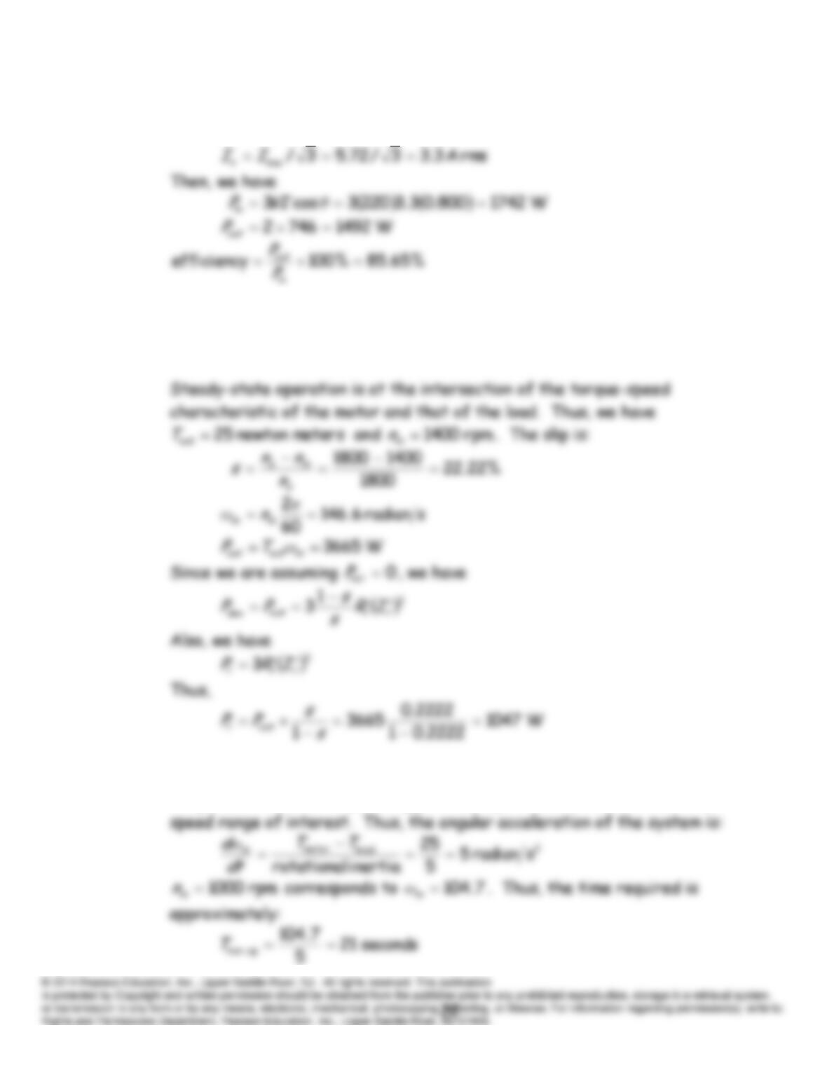
P17.29 Because the machine is delta connected, the magnitude of the phase
current is:
P17.30 The no-load speed is approximately 1800 rpm. Thus, the synchronous
speed appears to be 1800 rpm, and we have a four-pole motor.
P17.31 As an engineering estimate, we take the difference between the motor
torque and the load torque as approximately 25 newton meters over the
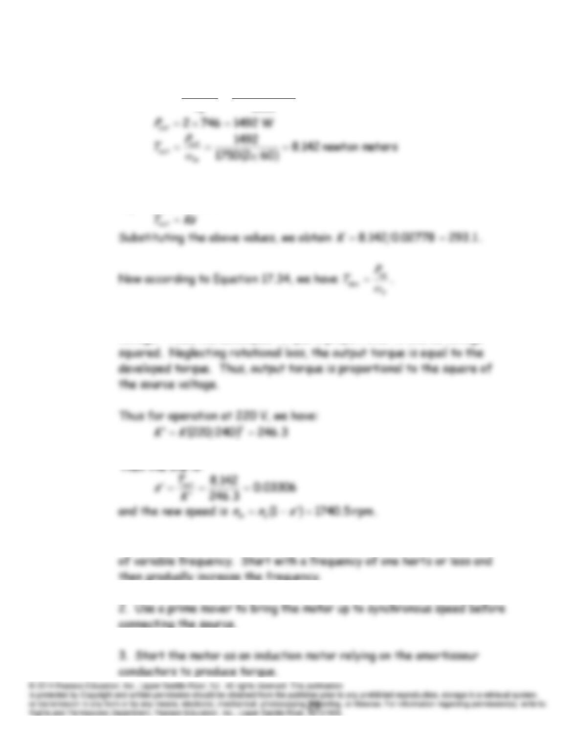
P17.32 Under the conditions given, we have
02778.0
1800
17501800
ms
n
nn
s
As an approximation, we assume that the output torque is proportional to
slip. Thus, we have:
However, the air-gap power is proportional to the square of the source
voltage. Thus, the developed torque is proportional to source voltage
P17.33* 1. Use an electronic system to convert 60-Hz power into three-phase ac
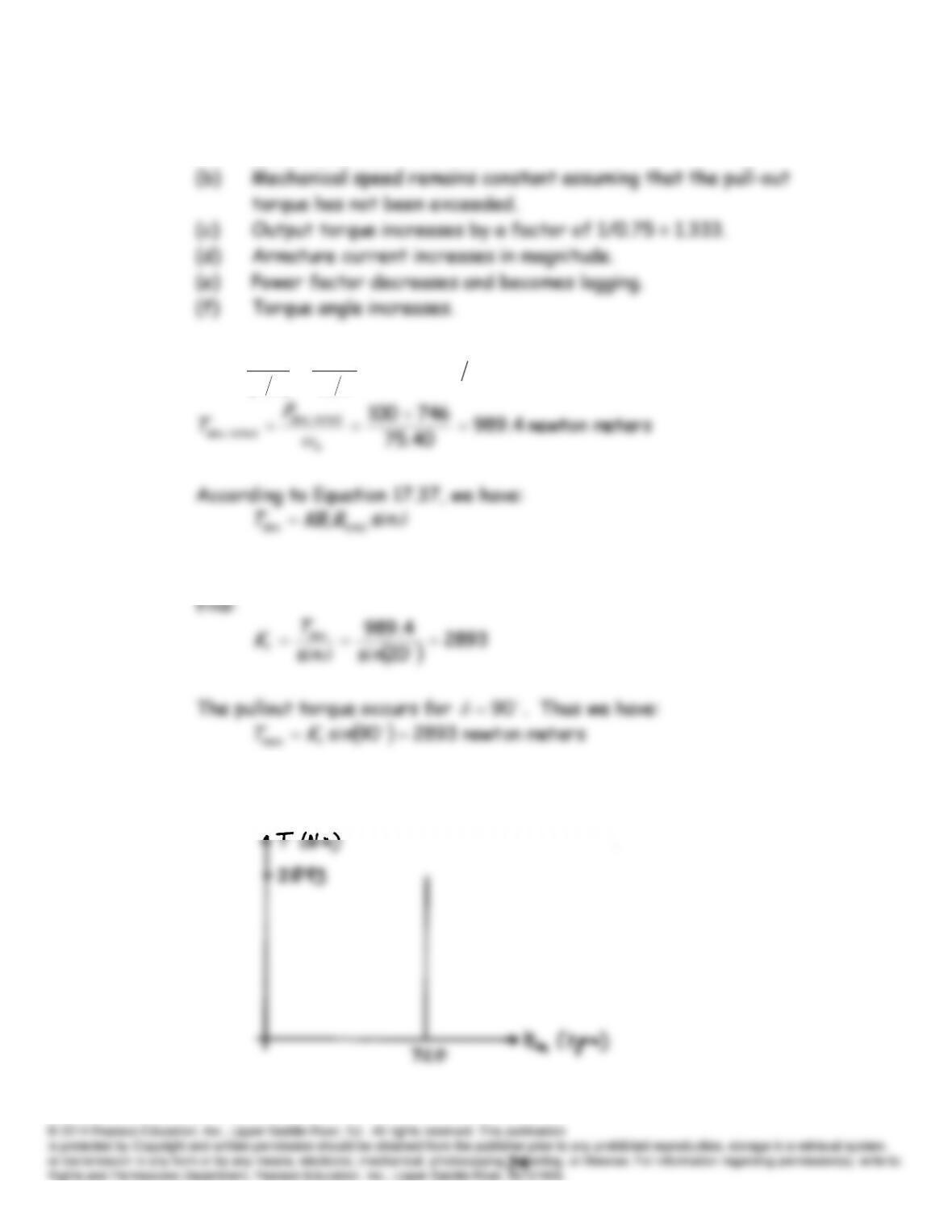
P17.34* (a) Field current remains constant. The field circuit is independent of
the ac source and the load.
P17.35*
srad 40.75
210
602
2 πω
ω
P
s
rpm 720
s
n
We define
total
BKBKrt
. Then from the rated operating conditions, we
The torque speed characteristic is:
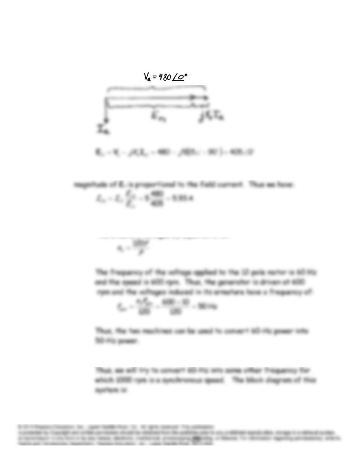
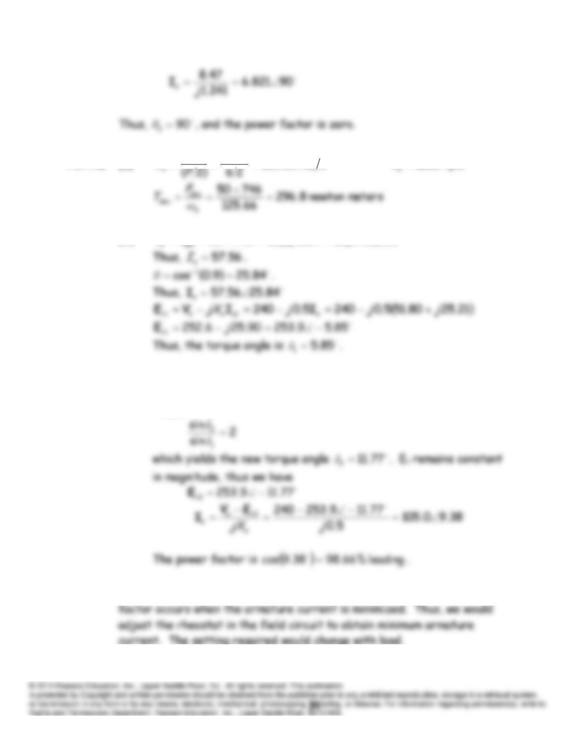
P17.36* For zero developed power, the torque angle is zero. The phasor diagram
is:
To achieve zero armature current, we must have
0480
2
a
r
VE
. The
P17.37* (a) The speed of a synchronous machine is related to the frequency of
the armature voltages by Equation 17.14:
(b) 1000 rpm is not the synchronous speed for any 60-Hz motor.
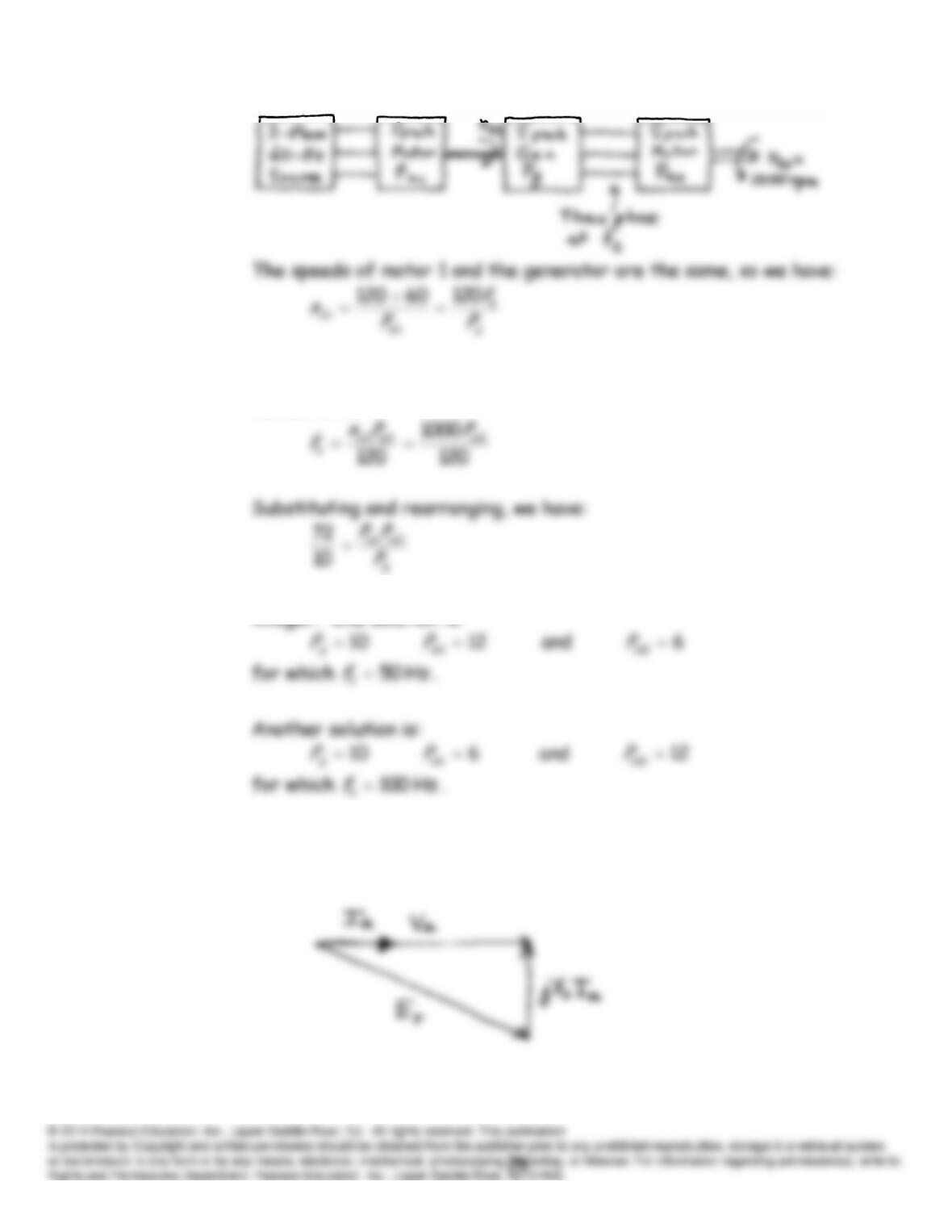
The frequencies are the same for the generator and motor 2, so
we can write:
Of course, the number of poles on each machine must be an even
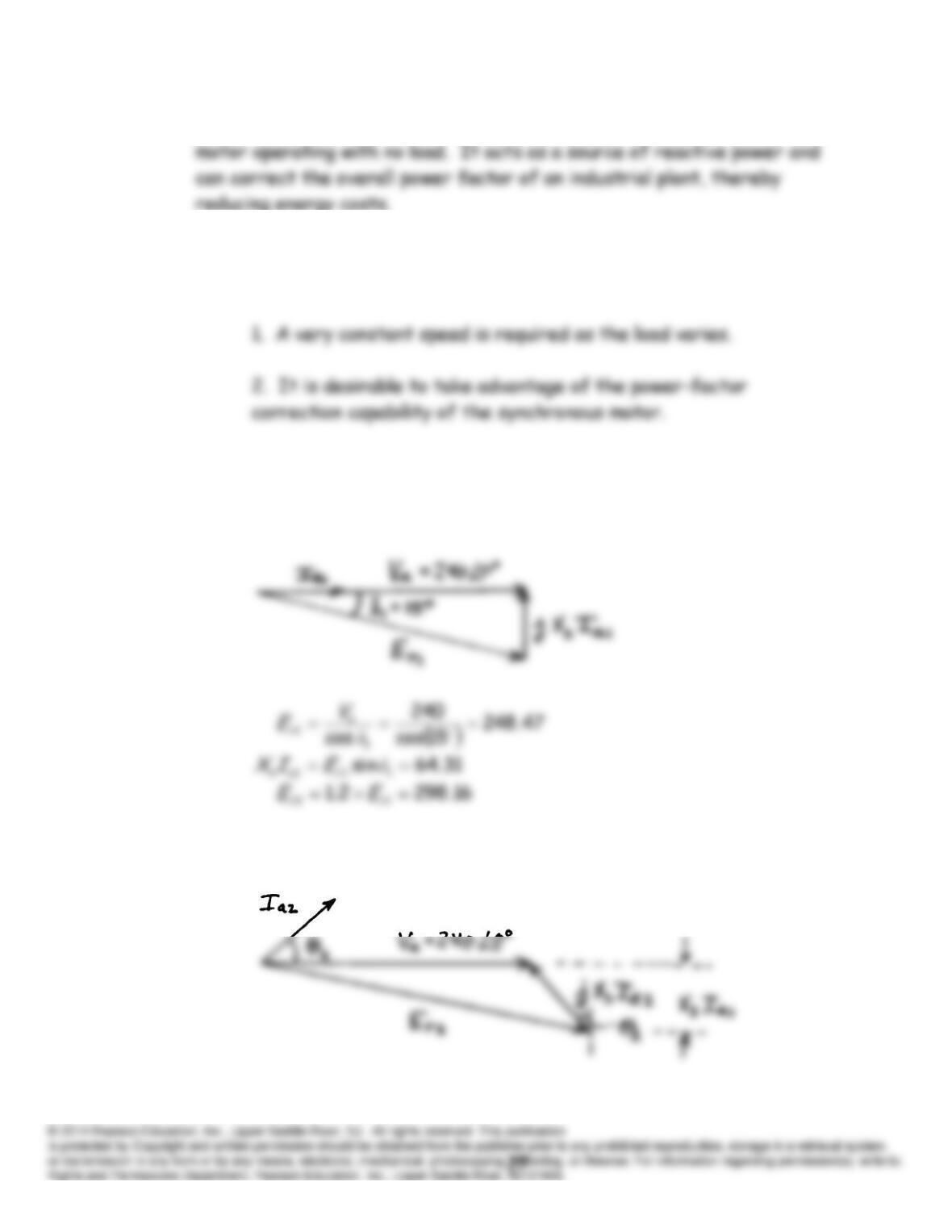
P17.38 See Figure 17.23 in the text for the V curves. The phasor diagram
corresponding to the minimum point of a curve is:
P17.39 A synchronous capacitor is an overexcited three-phase synchronous
P17.40 Two situations in which a synchronous motor is a better choice than an
induction motor are:
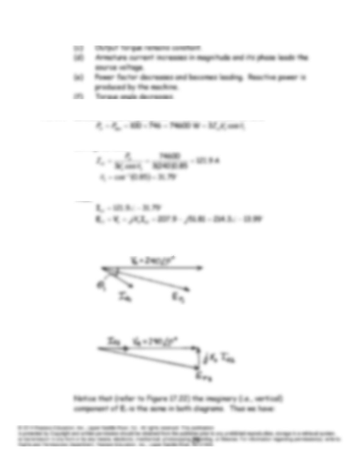
P17.41 Refer to Figure 17.22 for the phasor diagrams with constant developed
power and variable field current. The phasor diagram for the initial
operating conditions is:
The phasor diagram for the second operation condition is:
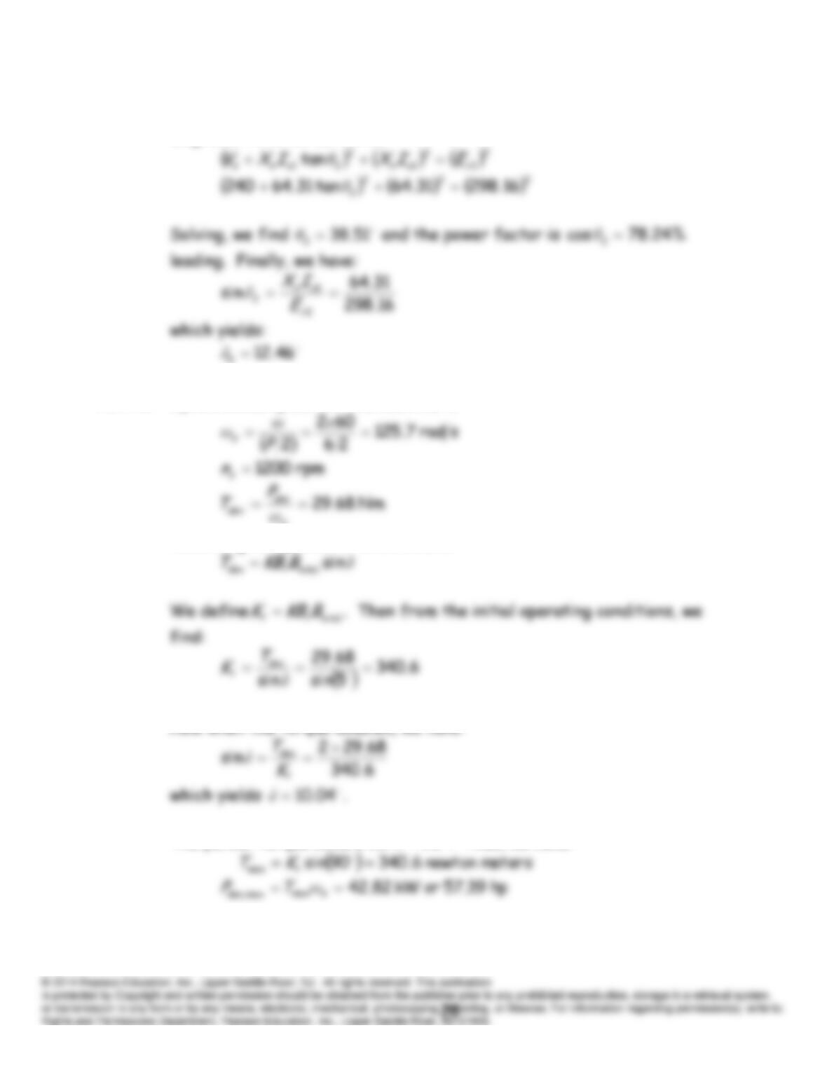
Notice that the vertical component of
as
jX
I
is the same in both
diagrams. Now we can write:
P17.42 Synchronous speed for the machine is:
s
According to Equation 17.37, we have:
Now when the torque doubles, we have
The pullout torque occurs for
90δ
. Thus, we have:
P17.43 (a) Output power remains constant.
(b) Mechanical speed remains constant.
P17.44 Because the developed power includes the losses, we have:
Solving, we have
Thus,
The phasor diagram is:
For 100% power factor, the phasor diagram becomes:
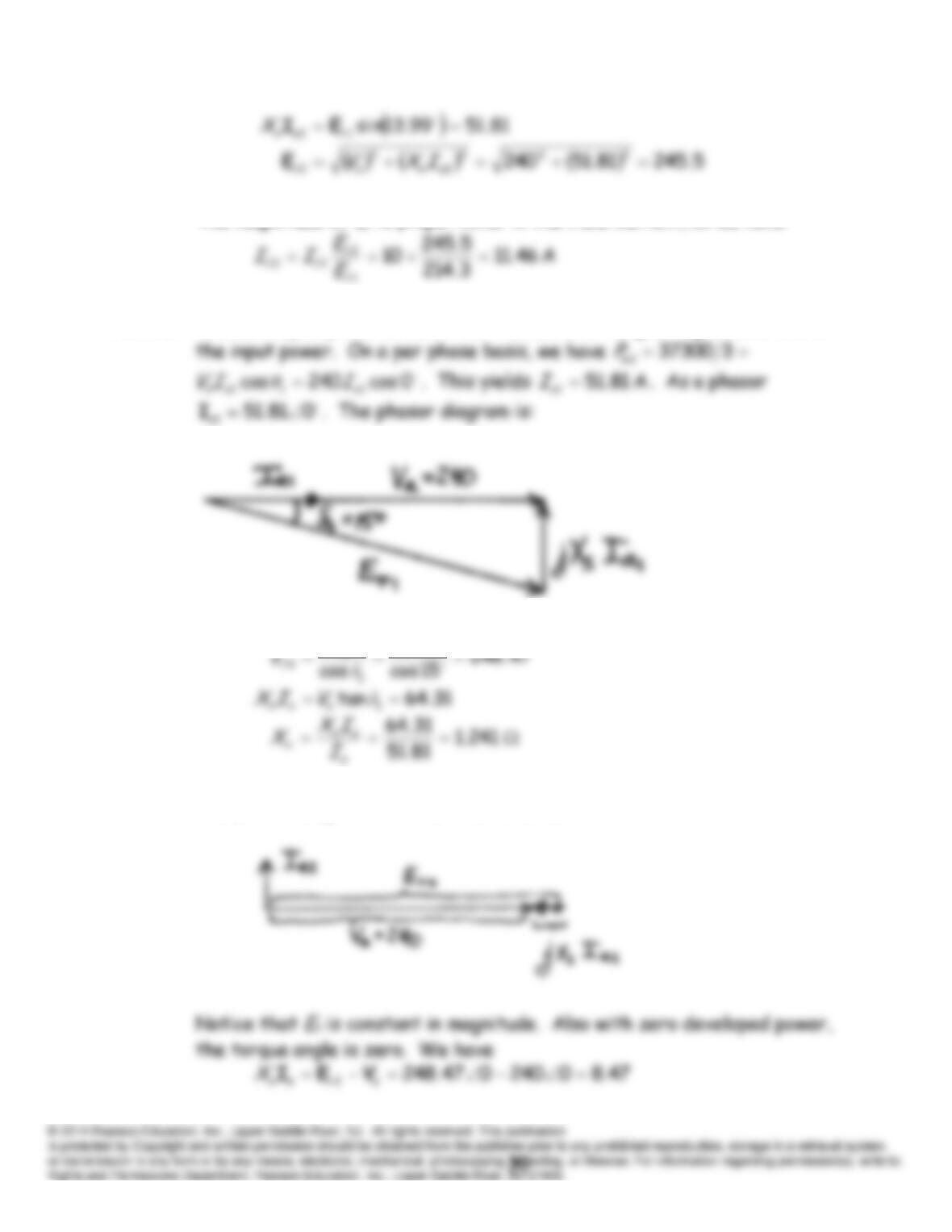
The magnitude of
Er
is proportional to the field current, so we have:
P17.45 The developed power is
W 3730074650
. Neglecting losses, this is
240
a
V
The phasor diagram with the load removed is:
P17.46 (a)
srad 66.125
602
ω
rpm 1200
n
(b)
9.02403cos374650
θ
(c) To double the power, we must double the torque. According to
Equation 17.37, the developed torque is proportional to
δsin
.
Thus,
P17.47 Referring to the V-curves shown in Figure 17.23, we see that unity power
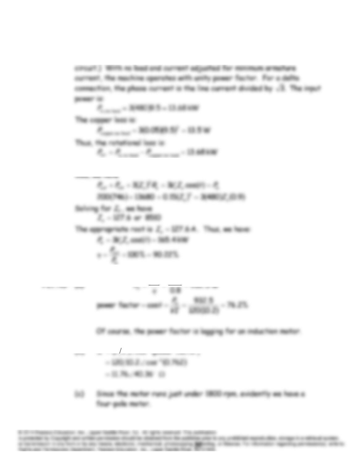
P17.48 The machine has copper-losses in the armature windings and rotational
losses. (We do not consider the power that must be supplied to the field
We assume that the rotational loss is independent of the load. At full-
746
out
P
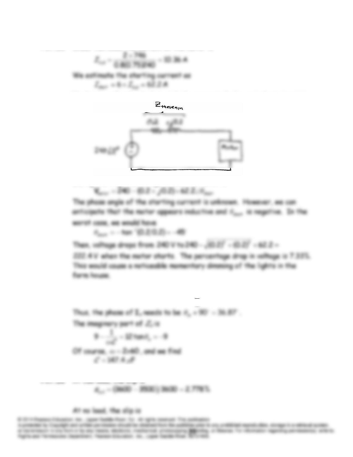
P17.50* Under full load, the current of the motor is
Neglecting other loads that might be connected, the equivalent circuit is
During starting, the voltage across the motor is
P17.51 The phase angle of
13.53
6
8
arctan is
mm
θI
.
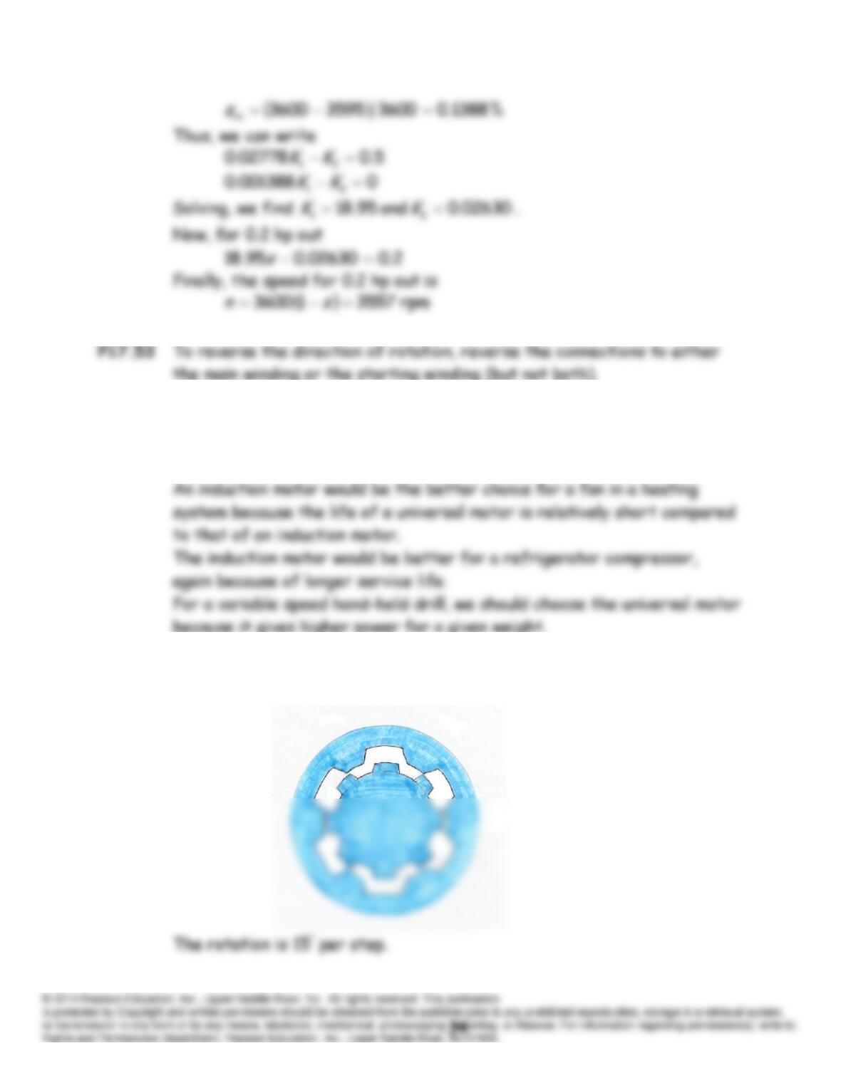
P17.54 A universal motor would be better than an induction motor in a portable
vacuum cleaner because the universal motor gives a higher power to
weight ratio.
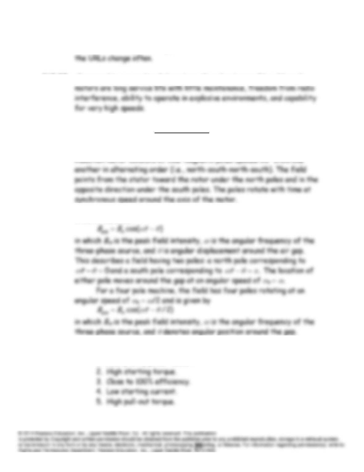
P17.55 A sketch of a stepper motor cross section with 6 stator poles and 8 rotor
poles is:
P17.56 Many sites dealing with stepper motors can be found on the internet but
P17.57 Compared to conventional dc motors, the advantages of brushless dc
Practice Test
T17.1 (a) The magnetic field set up in the air gap of a four-pole three-phase
(b) The air gap flux density of a two-pole machine is given by Equation
17.12 in the book:
T17.2 Five of the most important characteristics for an induction motor are:
1. Nearly unity power factor.
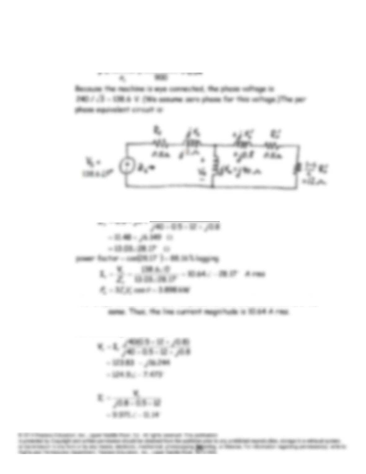
T17.3 An eight-pole 60-Hz machine has a synchronous speed of
ns
900 rpm,
and the slip is:
864900
ms
nn
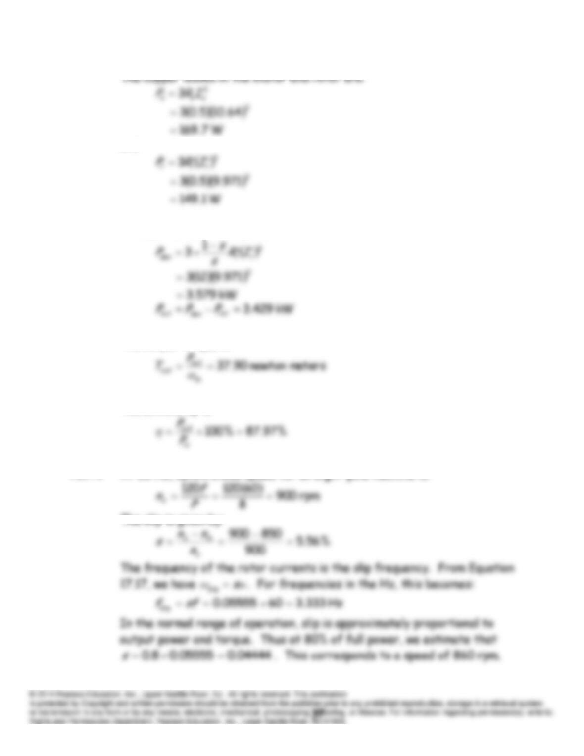
Then, we have
8.0125.040
jj
For a wye-connected motor, the phase current and line current are the
Next, we compute
rx
IV
and
.
and
Finally, the developed power is:
The output torque is:
The efficiency is:
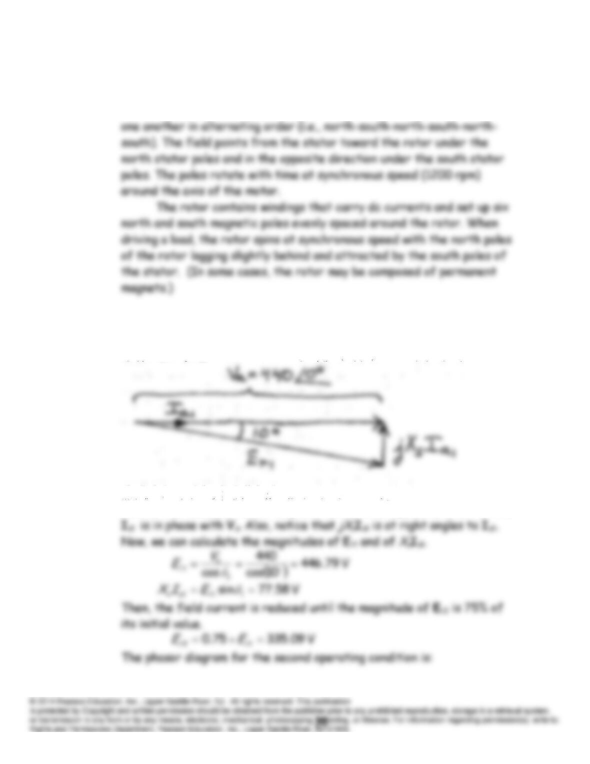
T17.4 At 60 Hz, synchronous speed for an eight-pole machine is:
The slip is given by:
T17.5 The stator of a six-pole synchronous motor contains a set of windings
(collectively known as the armature) that are energized by a three-phase
ac source. These windings produce six magnetic poles spaced 60 from
T17.6 Figure 17.22 in the book shows typical phasor diagrams with constant
developed power and variable field current. The phasor diagram for the
initial operating conditions is:
Notice that because the initial power factor is unity, we have
1 0 and
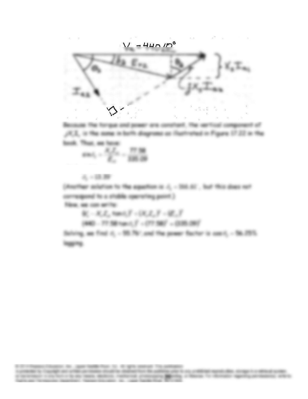
which yields: