CHAPTER 17
Exercises
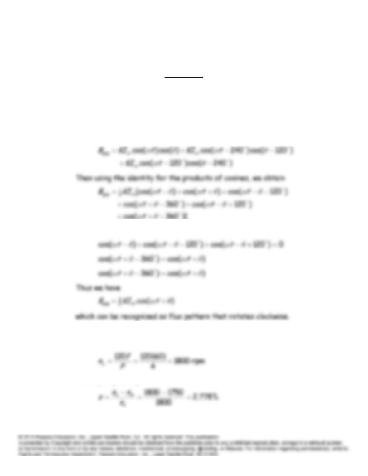
E17.1 From Equation 17.5, we have
)240cos()()120cos()()cos()(
gap
tKitKitKiBc
b
a
Using the expressions given in the Exercise statement for the currents,
we have
However we can write
E17.2 At 60 Hz, synchronous speed for a four-pole machine is:
The slip is given by:
The frequency of the rotor currents is the slip frequency. From Equation
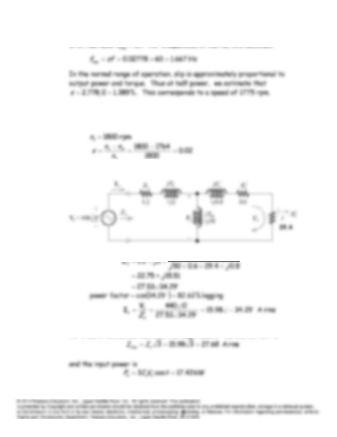
17.17, we have
ωω
s
. For frequencies in the Hz, this becomes:
E17.3 Following the solution to Example 17.1, we have:
s
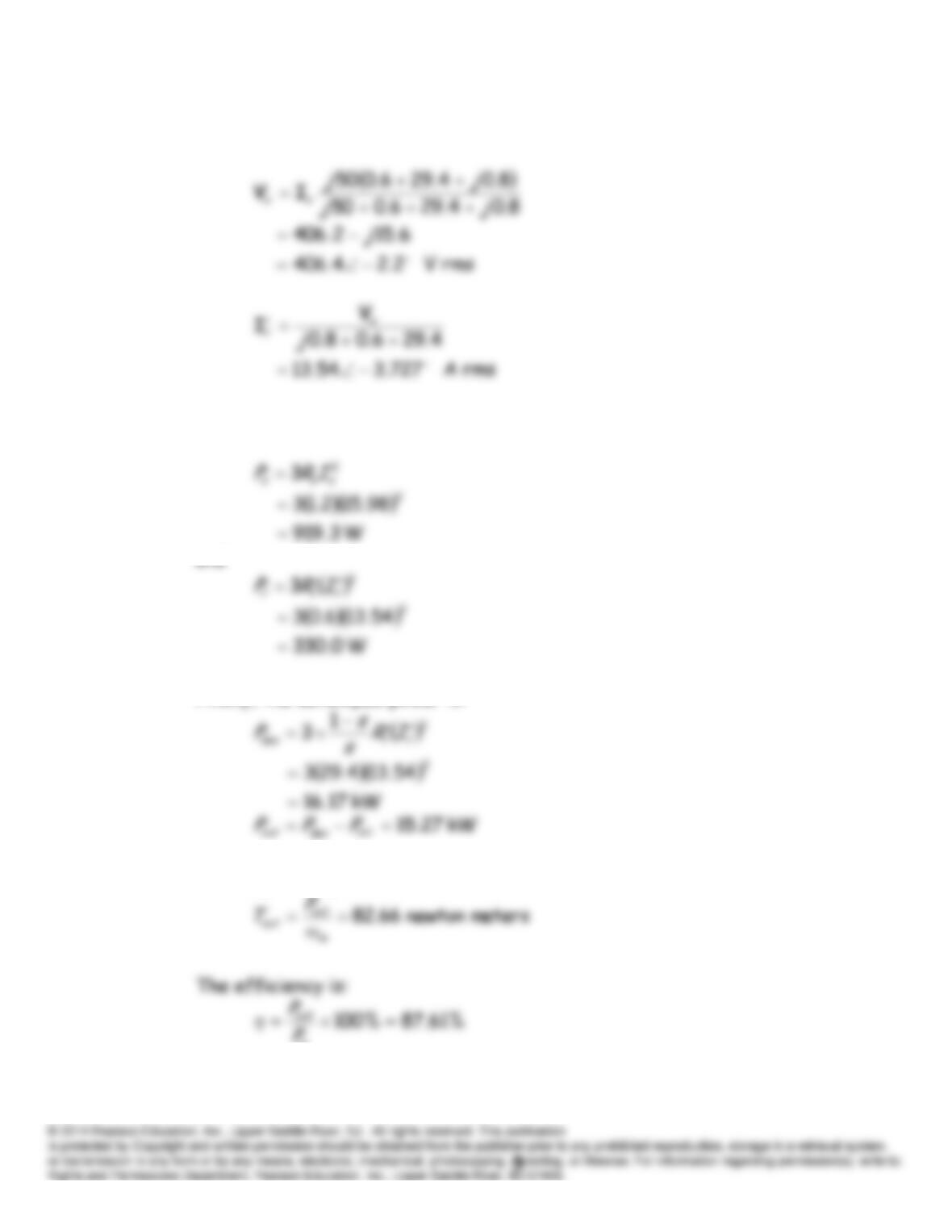
The per phase equivalent circuit is:
8.04.296.050
jj
For a delta-connected machine, the magnitude of the line current is
Next, we compute
rx
IV
and
.
The copper losses in the stator and rotor are:
and
Finally, the developed power is:
The output torque is:
in
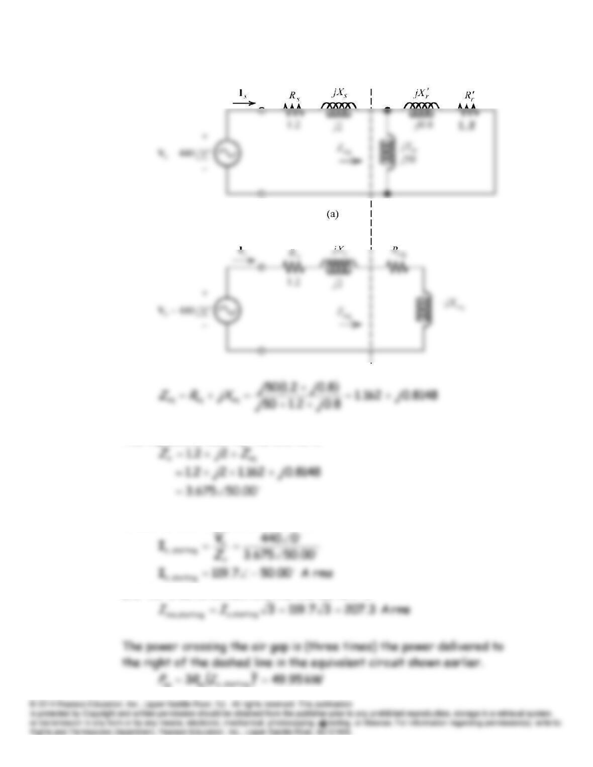
E17.4 The equivalent circuit is:
The impedance seen by the source is:
Thus, the starting phase current is
and for a delta connection, the line current is
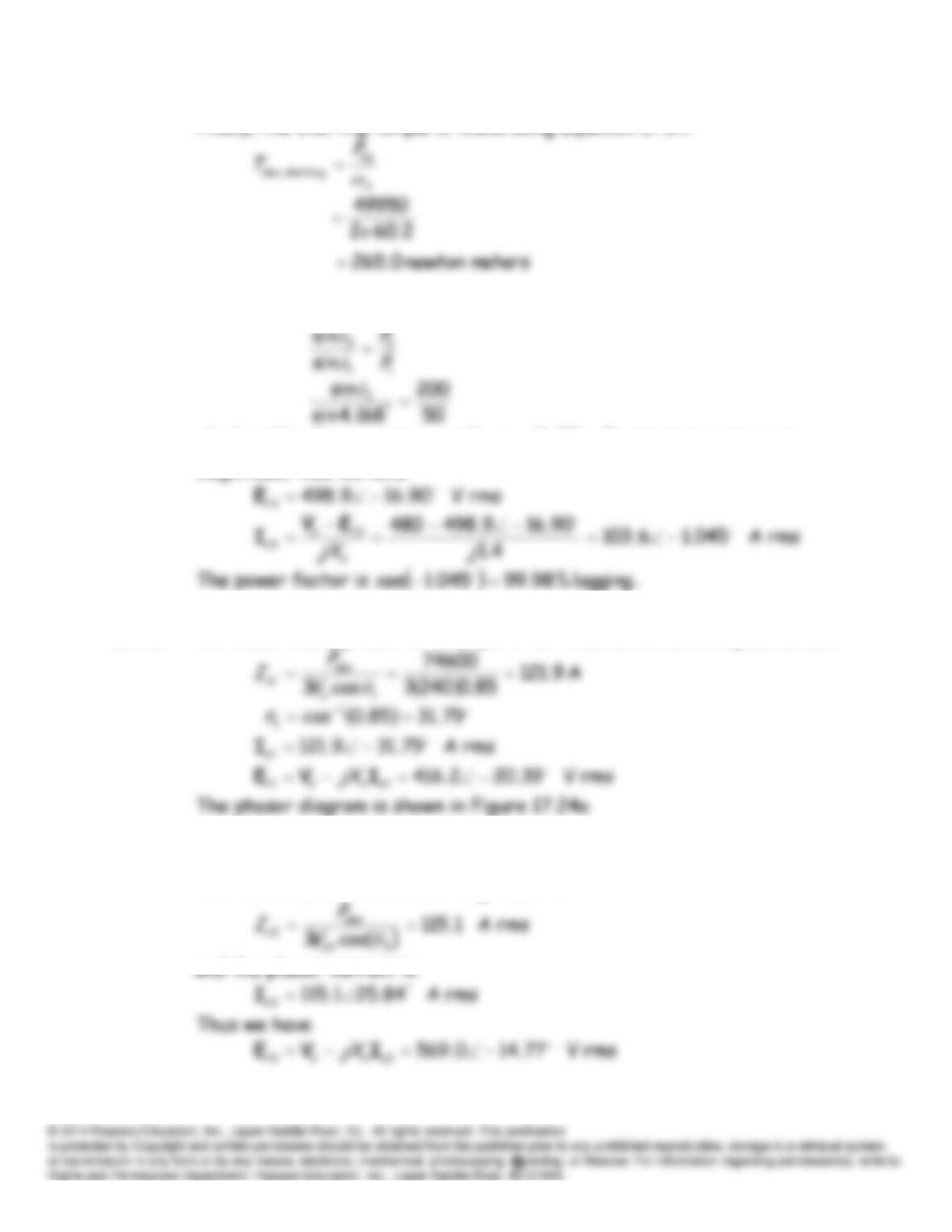
Finally, the starting torque is found using Equation 17.34.
E17.5 This exercise is similar to part (c) of Example 17.4. Thus, we have
which yields the new torque angle
90.16
3δ
. E
r
remains constant in
magnitude, thus we have
E17.6 We follow the approach of Example 17.5. Thus as in the example, we have
For 90% leading power factor, the power angle is
.84.25)9.0(cos 1
3
θ
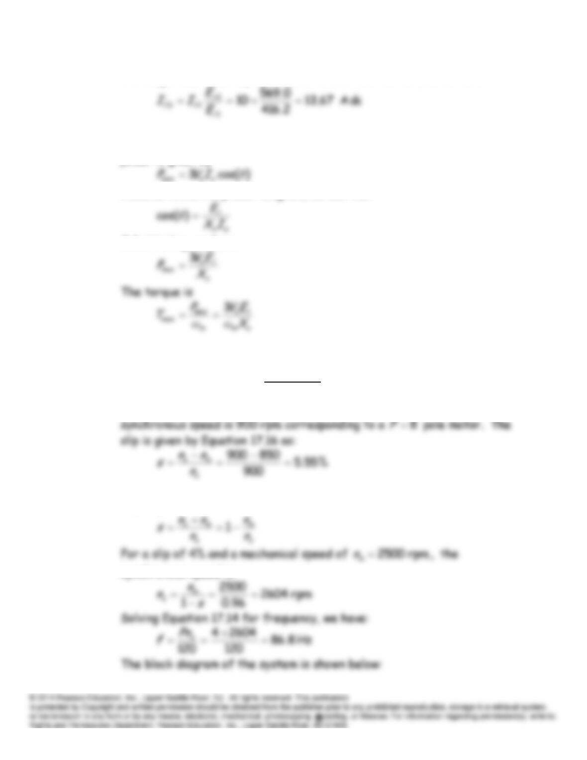
The new value of the current magnitude is
The magnitude of
Er
is proportional to the field current, so we have:
E17.7 The phasor diagram for
90δ
is shown in Figure 17.27. The developed
power is given by
However from the phasor diagram, we see that
Substituting, we have
Problems
P17.1* From Table 17.1, we see that for a speed of 850 rpm the next greatest
P17.2* Slip is given by:
synchronous speed is:
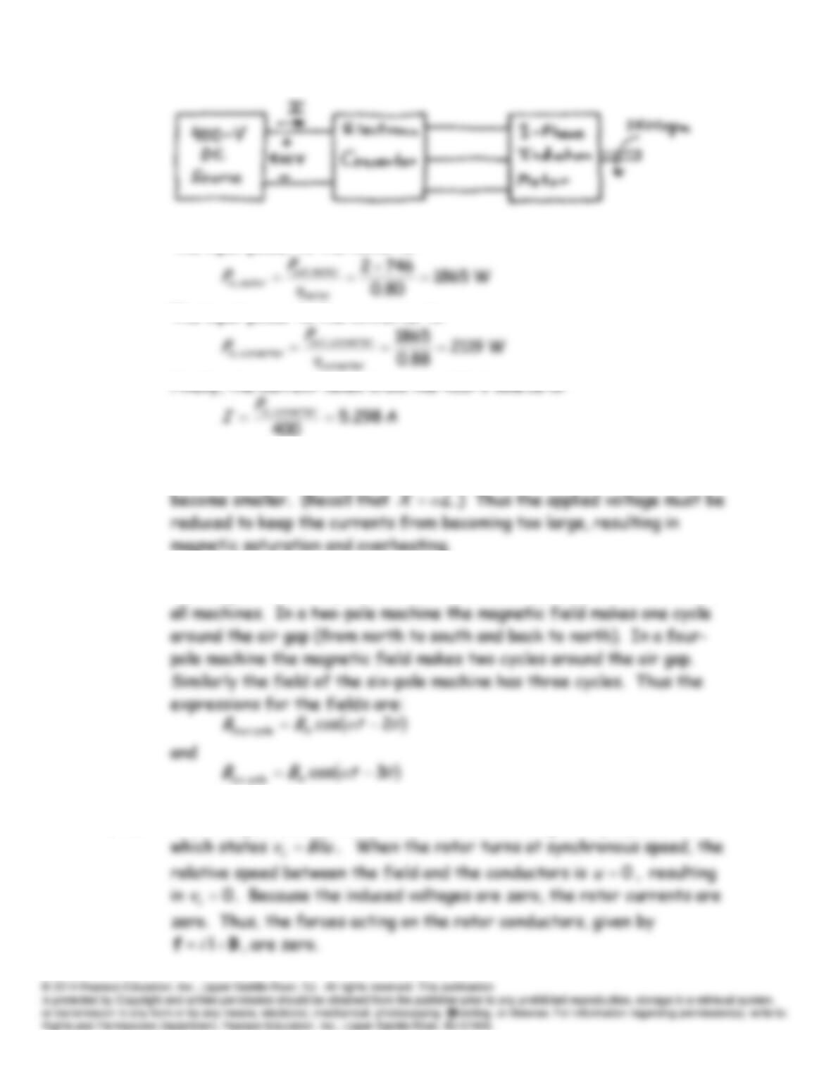
The input power to the motor is:
The input power to the converter is:
P17.3* As frequency is reduced, the reactances
rms XXX
and , ,
of the machine
P17.4* The magnetic field is periodic with the same frequency as the source for
P17.5 The voltages induced in the rotor conductors are given by Equation 17.15
P17.6 From Equation 17.14, we have:
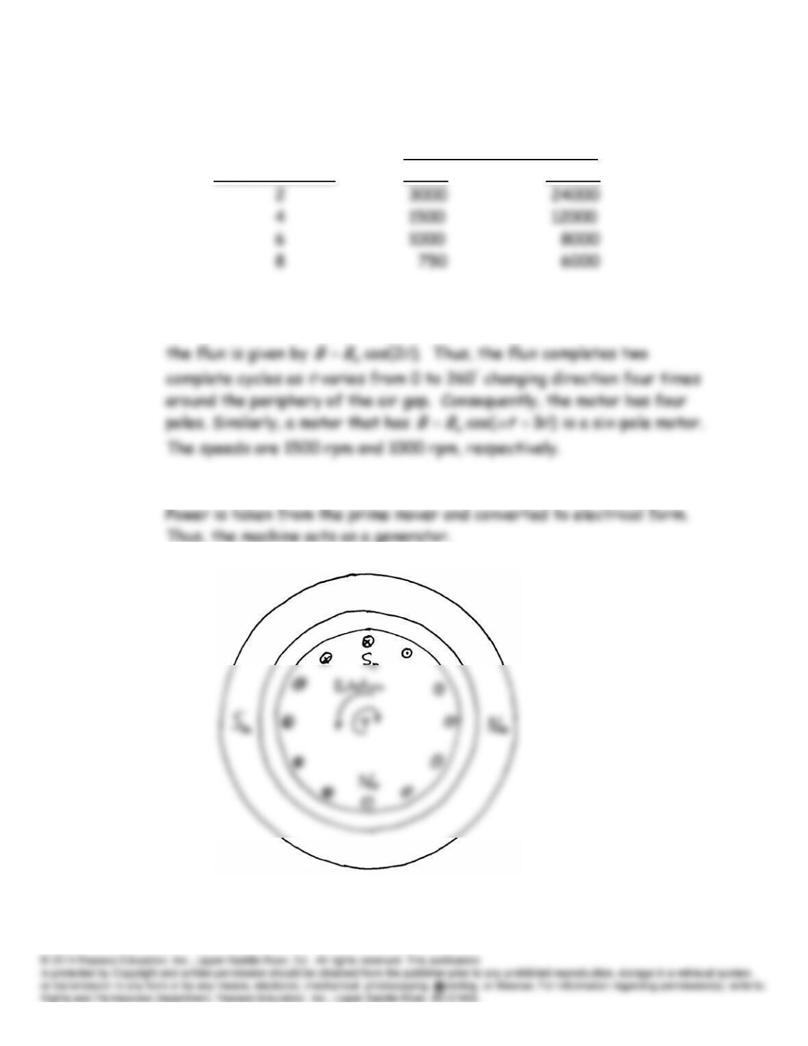
Synchronous Speed in rpm
Number of Poles 50 Hz 400 Hz
P17.7 First consider an air-gap flux given by
)2cos(
tBB m
. For
,0
t
P17.8 In this case the developed torque opposes the direction of rotation.
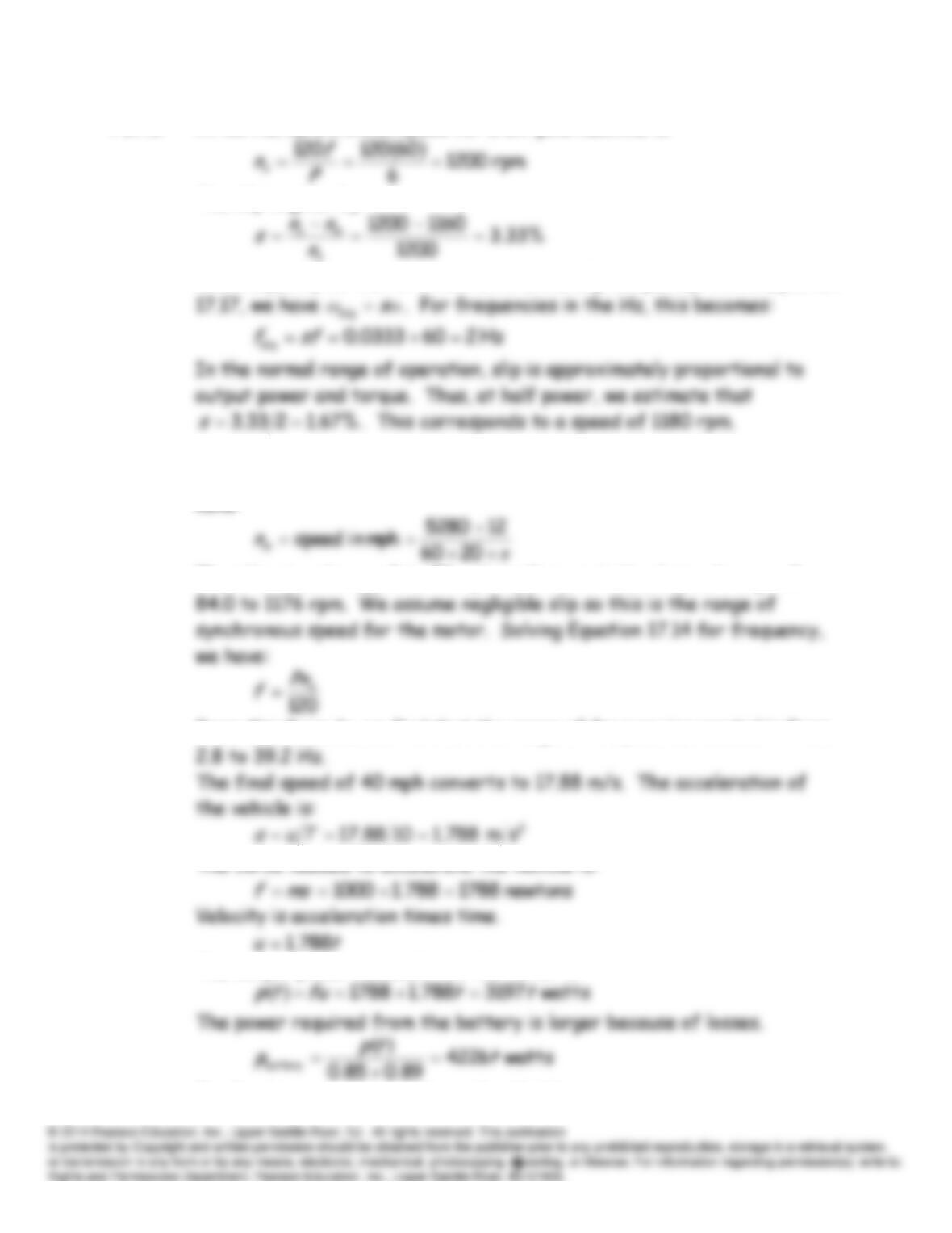
P17.9 At 60 Hz, synchronous speed for a six-pole machine is:
The slip is given by:
The frequency of the rotor currents is the slip frequency. From Equation
P17.10 (a) To convert speed in mph to revolutions of the tire per minute, we
have:
Thus the speed range 5 to 70 mph implies a rotational speed range of
From this formula, we find that the range of frequencies needed is from
The force needed to accelerate the vehicle is:
The output power needed from the motor is:
Finally, the current taken from the 48-V battery is:
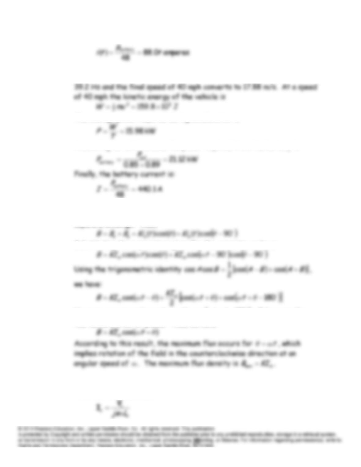
(b) As in part (a), the range of frequencies needed ranges from 2.8 to
The average power required during acceleration is:
Accounting for efficiencies, the power required from the battery is:
P17.11 The total field in the machine is the sum of the fields produced by the
separate windings. Thus,
Substituting the expressions given for the currents, we have:
However, we can write
0180coscos
θωθω
tt
because the
two terms are out of phase. Thus, we have:
P17.12 With zero resistance for the rotor conductors, Equation 17.19 for the
rotor currents becomes
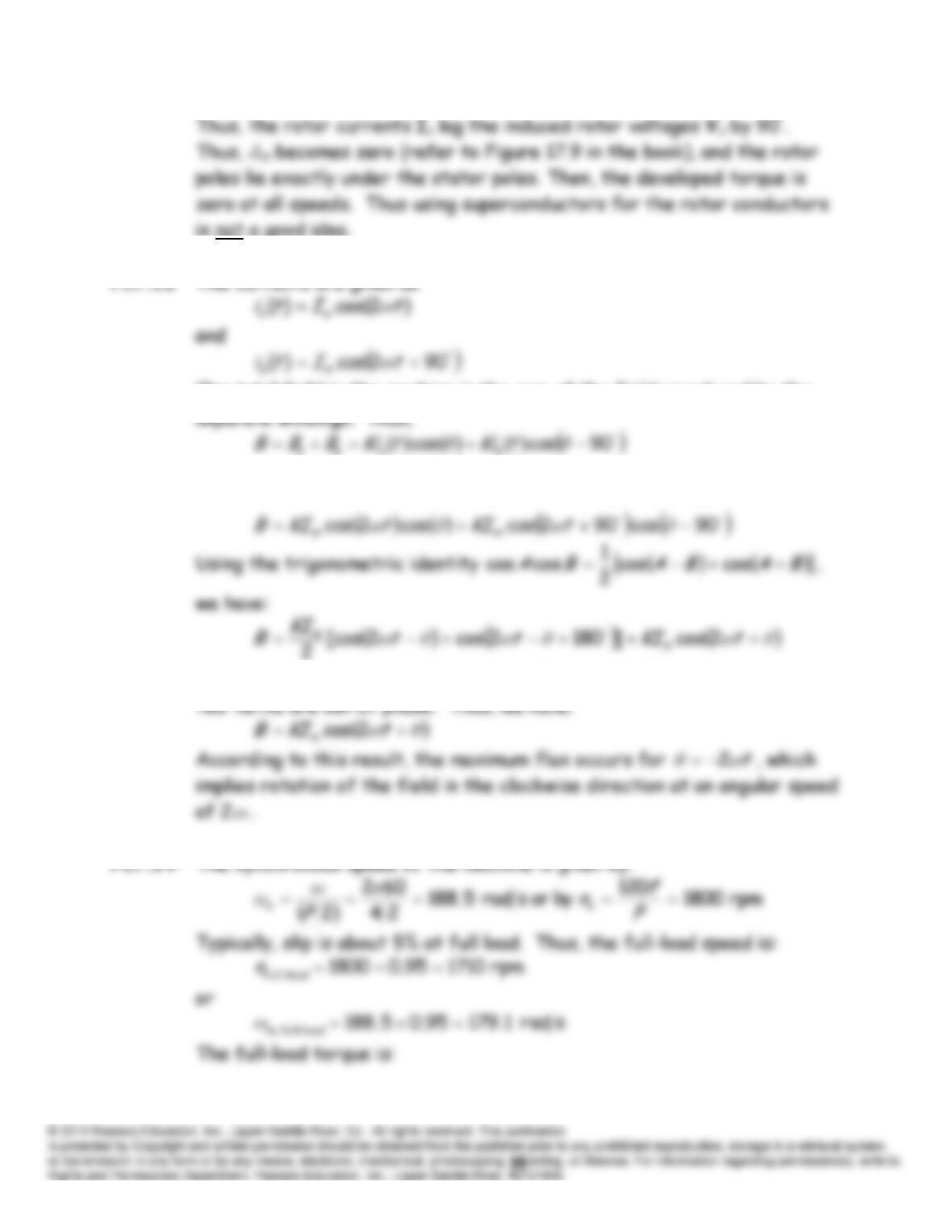
The total field in the machine is the sum of the fields produced by the
Substituting the expressions given for the currents, we have:
However, we can write
0180coscos
tt
because the
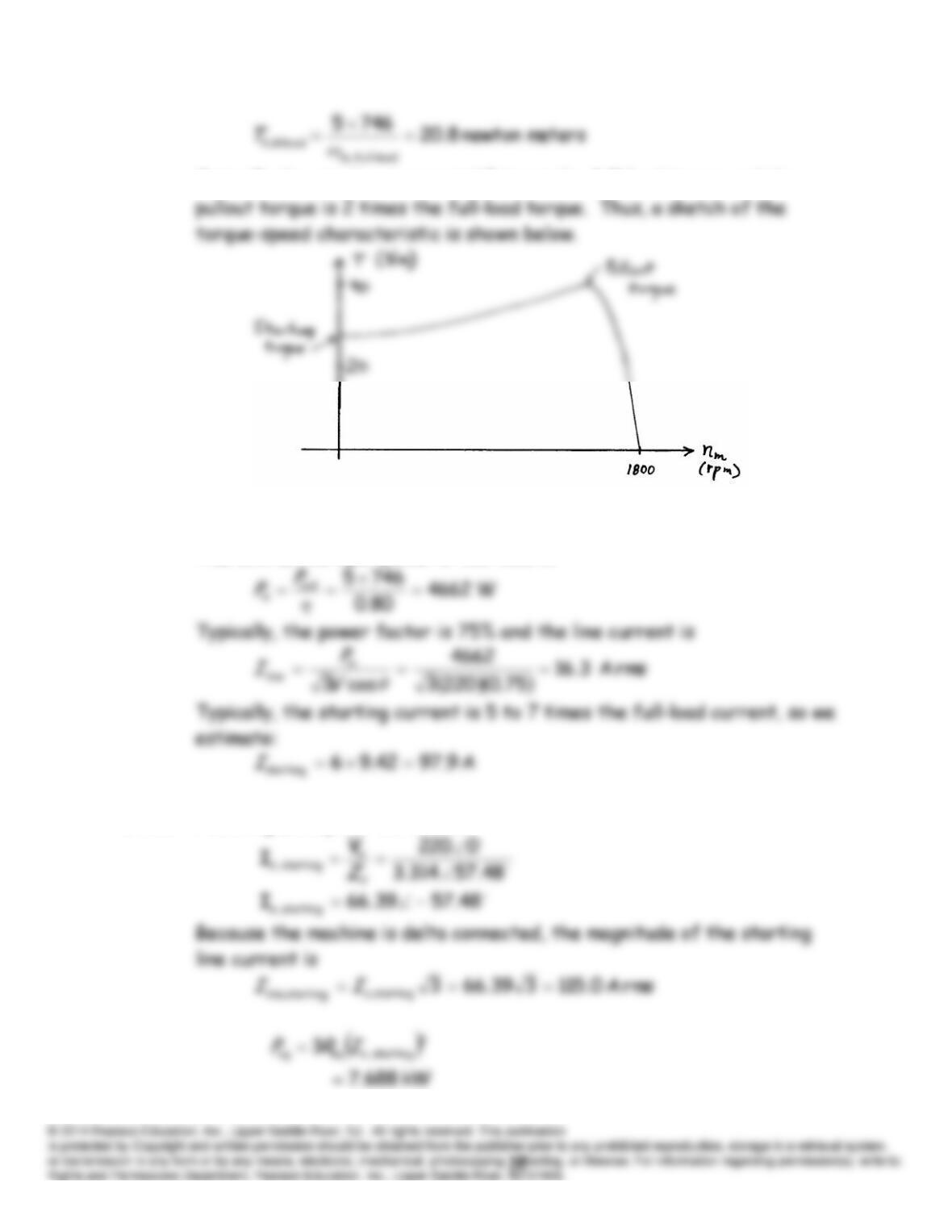
Typically the starting torque is 1.5 times the full-load torque and the
We estimate the efficiency of a typical machine such as this as 80%.
Therefore, the input power at full load is:
P17.15* Following Example 17.2, we find
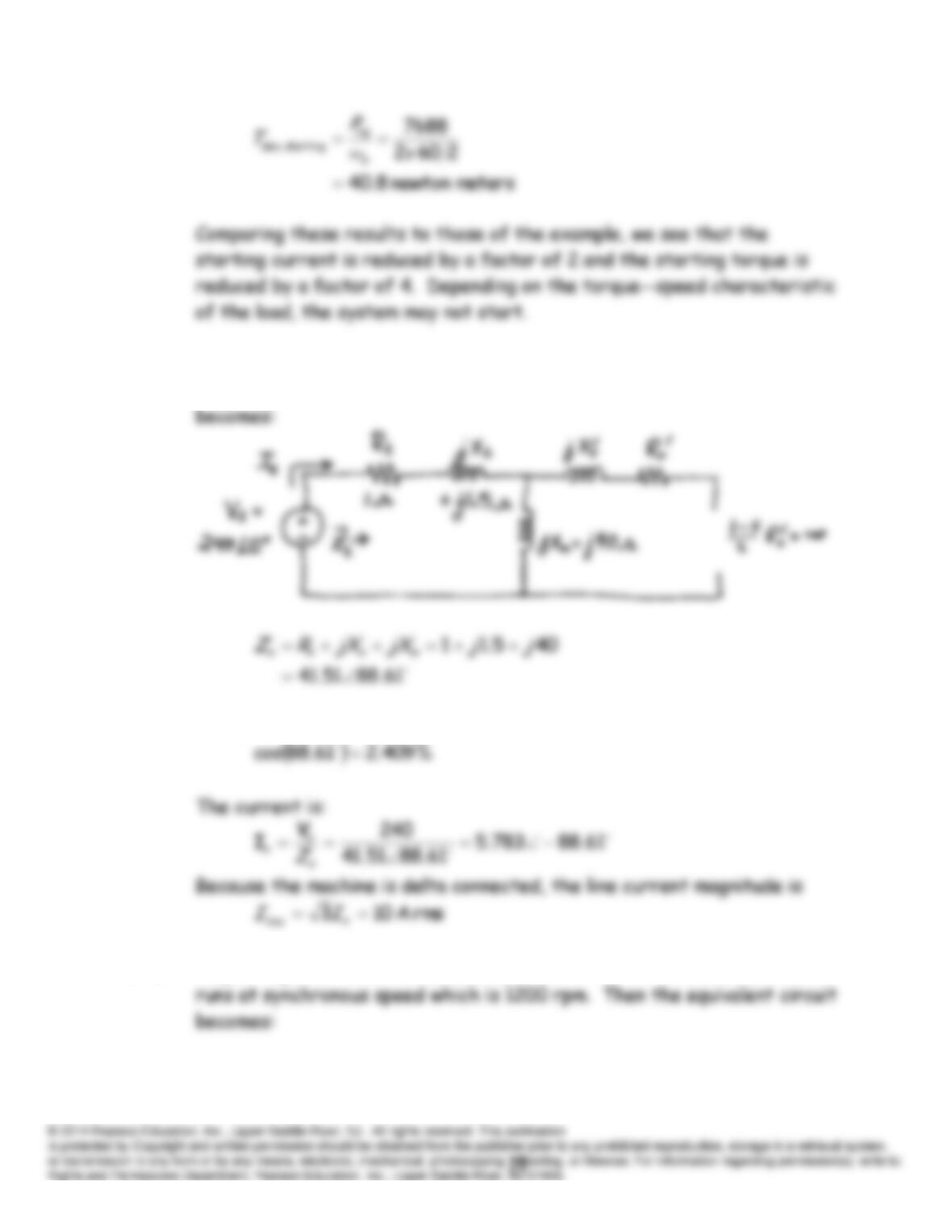
P17.16* Neglecting rotational losses, the slip is zero with no load, and the motor
runs at synchronous speed which is 1800 rpm. Then the equivalent circuit
The power factor is:
P17.17* Neglecting rotational losses, the slip is zero with no load, and the motor
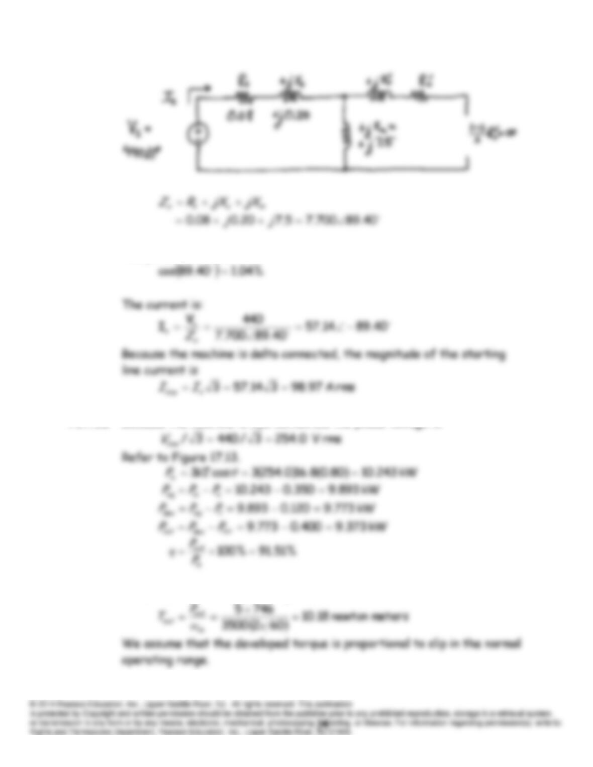
The power factor is:
P17.18* Because the machine is wye connected the phase voltage is:
P17.19* First, the full-load output torque is:
P17.20 The two basic types of rotor construction for induction motors are the
P17.21 Besides low cost, we usually would prefer an induction motor with:
1. High power factor.
P17.22 Refer to Figure 17.13. Neglecting the stator resistance
Rs
and rotational
losses, the only loss is rotor copper loss given by:
The developed power and the output power are equal and given by:
Now the efficiency is given by:
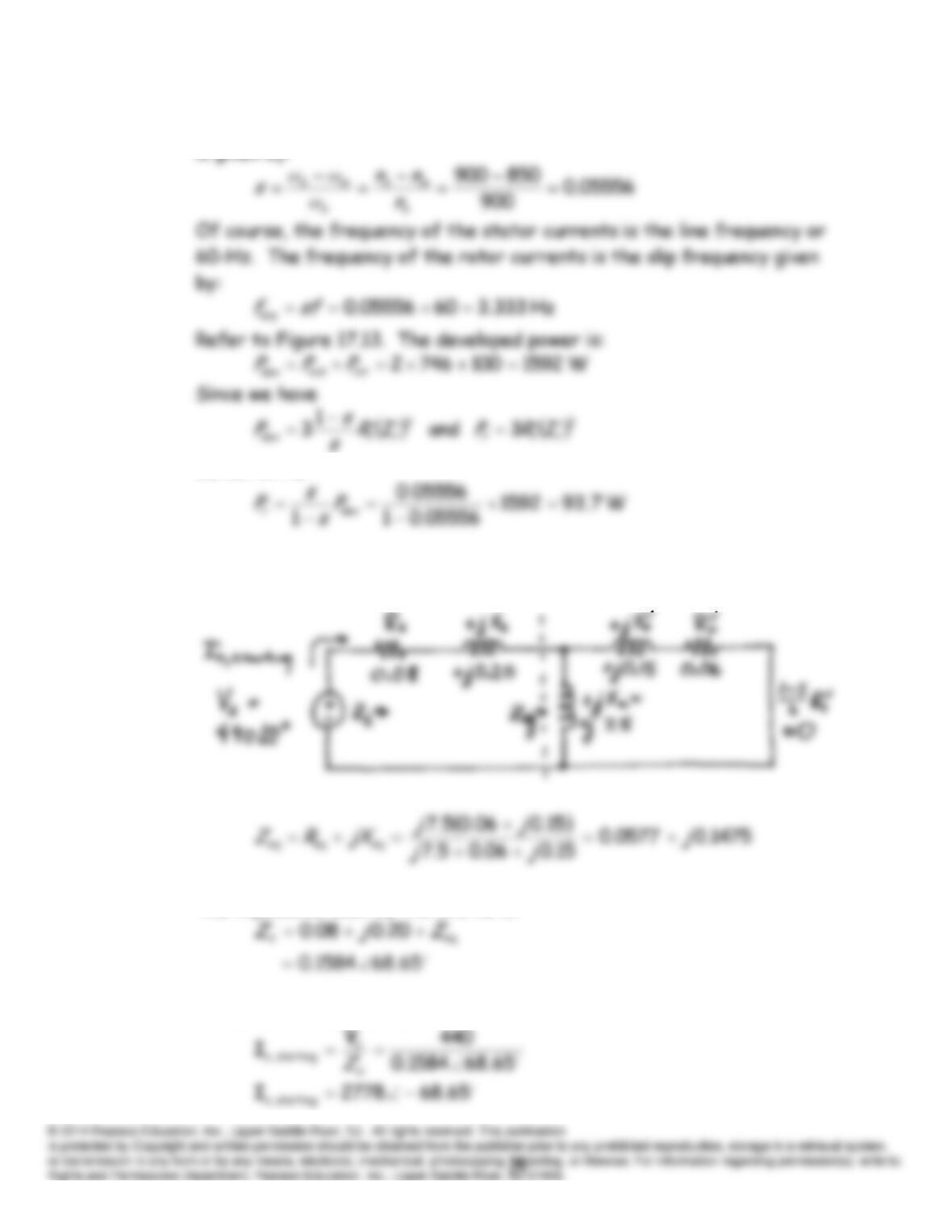
P17.23 Synchronous speed for an 8-pole 60-Hz motor is 900 rpm. Thus, the slip
we can write
P17.24 This is similar to Example 17.2. The equivalent circuit is:
The impedance seen by the source is:
Thus, the starting current is:
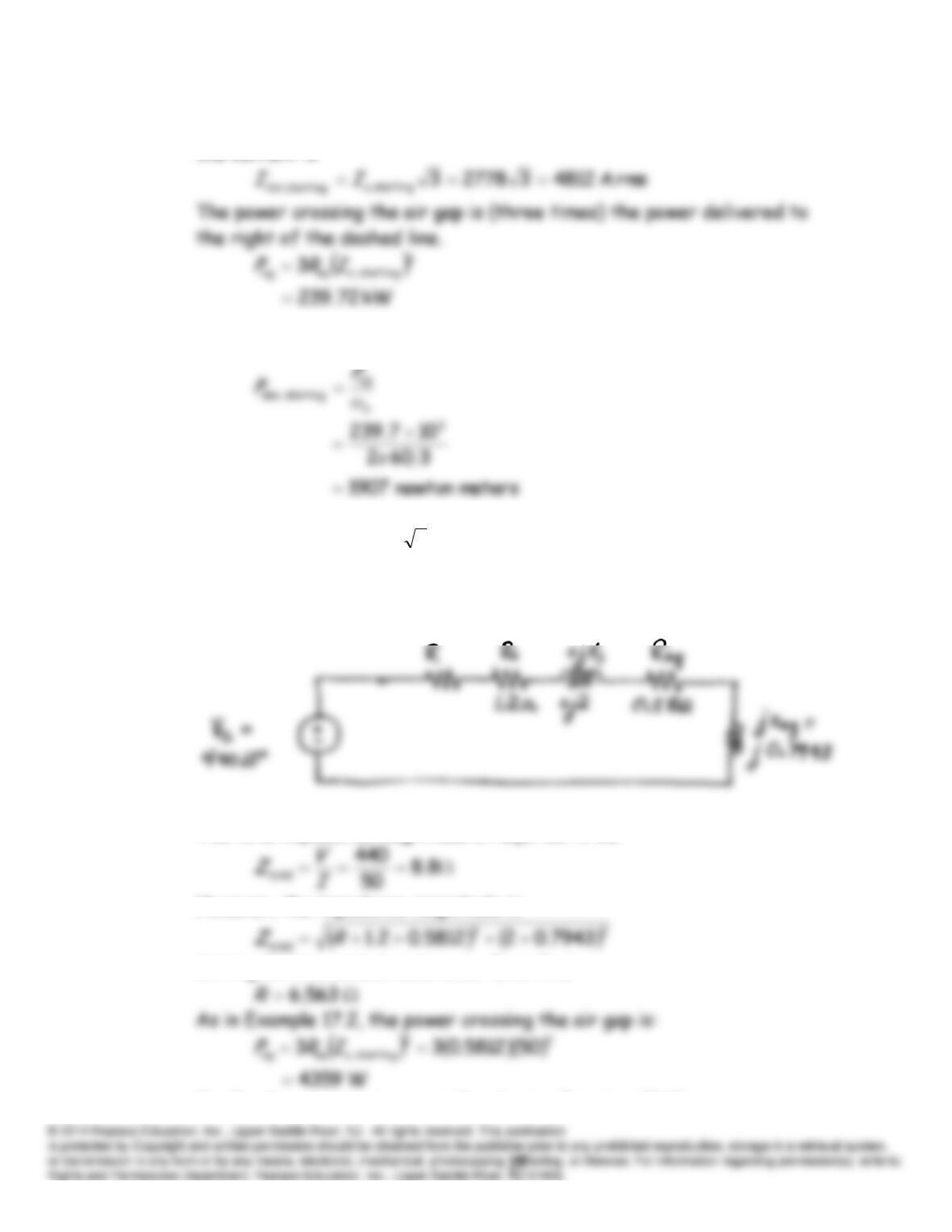
Because the machine is delta connected, the magnitude of the starting
line current is
Finally, the starting torque is found using Equation 17.34.
P17.25 For a line current of
A, 350
the phase current is 50 A. Equivalent
circuits for the machine under starting conditions are shown in Figure
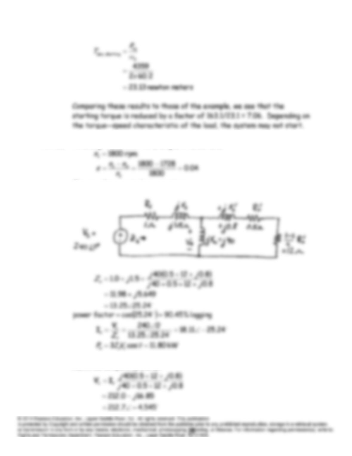
17.15. With the added resistance in series, we have the circuit
The total impedance magnitude is required to be:
However, the impedance magnitude is
Solving for the added resistance
R
, we find
Finally, the starting torque is found using Equation 15.34.
P17.26 Following the solution to Example 17.1, we have:
The per-phase equivalent circuit is:
Next, we compute
IV
and
.
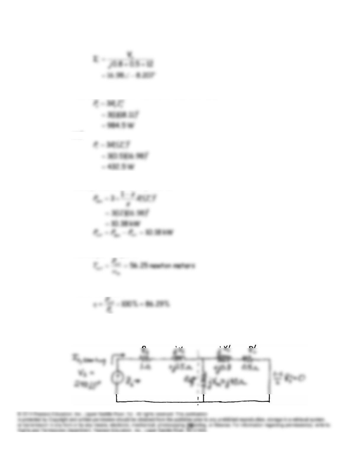
The copper losses in the stator and rotor are:
and
Finally, the developed power is:
The output torque is:
The efficiency is:
P17.27 This is similar to Example 17.2. The equivalent circuit is:
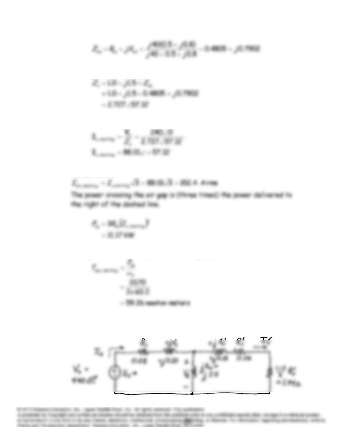
The impedance seen by the source is:
Thus, the starting current is:
Because the machine is delta connected, the magnitude of the starting
line current is
Finally, the starting torque is found using Equation 17.34.
P17.28 This is similar to Example 17.1. The per-phase equivalent circuit is: