CHAPTER 16
Exercises
E16.1 The input power to the dc motor is
loss
outsourcesource
in PPIVP
E16.2 (a) The synchronous motor has zero starting torque and would not be
able to start a high-inertia load.
E16.3 Repeating the calculations of Example 16.2, we have
2
T
V
(c)
A 333.3
2
f
ipull
m
E16.4 Referring to Figure 16.15 we see that
125
A
E
V for
2
F
I
A and
E16.5 Referring to Figure 16.15 we see that
145
A
E
V for
5.2
F
I
A and
E16.6
Ω 20
1010300
FF
T
IRV
R
E16.7 Following Example 16.4, we have
240
V
Referring to Figure 16.18 we see that
200
A
E
V for
6
F
I
A and
.1200
n
Thus we have
E16.8
rad/s 8.177
6
12
7.125
3
1
13
dev
dev
mm T
T
ωω
E16.9 With
RA
= 0 and fixed
VT
, the shunt motor has constant speed
independent of the load torque. Thus we have
E16.10 Decreasing
VT
decreases the field current and therefore the flux
. In
the linear portion of the magnetization curve, flux is proportional to the
E16.11 The torque—speed relationship for the separately excited machine is
given by Equation 16.27
E16.12 The torque—speed relationship for the separately excited machine is
given by Equation 16.27
E16.13
Problems
P16.1 The two types of windings found in electrical machines are field windings
P16.2 Dc motors are advantageous in automotive applications because dc power
P16.3 Dc machines contain brushes and commutators which act as mechanical
P16.5 The two principal types of three-phase motors are induction motors and
P16.6* Two disadvantages of dc motors compared to signal-phase ac induction
motors for a ventilation fan, which we can expect to operate most of the
P16.7*
%100 regulation speed
load–fullload–no
n
nn
P16.8 The input power is the output power divided by the efficiency.
Solving Equation 16.1 for the line current, we have
2
2 ππ
P16.10* At full load, we have:
sradian 3.183
2
1750
2 ππ
ω
Starting with rated voltage, we have:
Starting with reduced line voltage, we estimate:
P16.11 Rearranging Equation 16.9 we have
33.33120/)4(1000120/
Pnf s
P16.12 First, we determine the value of the constant
K
.
The equation for the torque—speed characteristic shown in Figure P16.12
Solving, we find the equilibrium speed as:
The torque is:
P16.13
θcos3 rmsrms
load–full in,
IVP
out
load–full in,load–full loss,
PPP
%100
out
P
η
θcos3 rmsrms
load–no in,
IVP
%100 regulation speed
load–fullload–no
nn
P16.14
W 52365440(14)0.8factor power
in
rmsrms IVP
P16.15*
sradian 4.120
2
1150
2 ππ
ω
out
in
loss
PPP
P16.16 (a) At nearly zero speed, the torque required by the load is 40 Nm but
(b) To find the speeds for which the system can run at a constant speed,
(c) If the speed becomes slightly less than the lower root, the load
P16.17 (a) For no load, we have:
(b) To find maximum torque, we have:
(c)
TP m
ω
P16.18 The no-load speed of an induction motor is very close to the synchronous
speed given by Equation 16.9:
in this case we have
f
= 60 Hz. Furthermore the number of poles must be
P16.19
W 25383007463
loss
out
in PPP
P16.20* In steady-state with no load, we have
uBeV A
T
and the current
A
i
is
zero.
P16.21* When the switch is closed, current flows toward the right through the
sliding bar. The force on the bar is given by:
Thus, the force is directed toward the bottom of the page. The starting
P16.22 The output power is
W 746 hp 1
P
. Thus,
Solving Equation 16.11 for the current and substituting values, we have:
P16.23 Under starting conditions
0
u
, we have
, ,0
A
T
AA RViuBe
and
Bif A
.
P16.24 As in Problem 16.21, we find that the starting force is 48.75 N. Since
this is greater than the load force (10 N) applied to the bar, the machine
Solving, we find that
The steady state velocity is:
(a) The power supplied by the voltage source is:
A
TiVP
in
(b) The power absorbed by the resistance is:
2
AA
RiRP A
(c) The mechanical output power is:
fuP
out
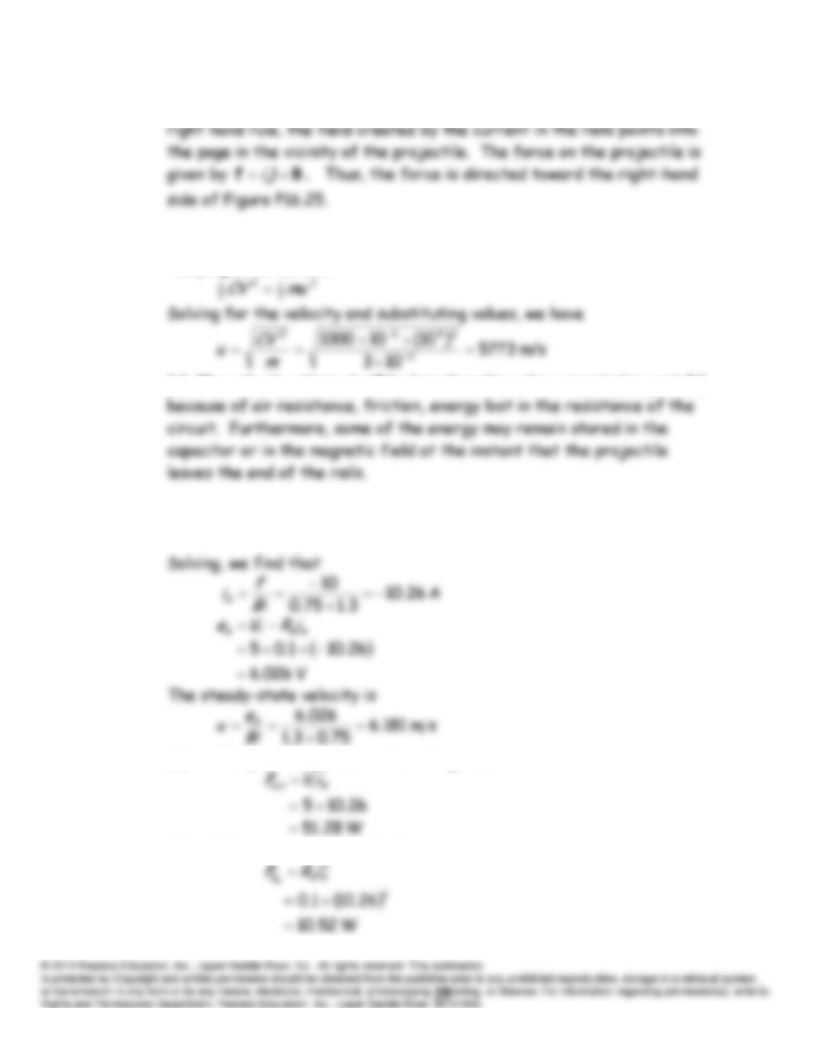
P16.25 (a) When the switch closes, current flows clockwise in the circuit. By the
(b) Equating the energy stored in the capacitor to the kinetic energy in
the projectile we have
(c) The velocity attained will be less than the value computed in part (b)
P16.26 In this case, the machine acts as a generator. We have:
Bif A
10
(a) The power supplied to the voltage source is
(b) The power absorbed by the resistance is
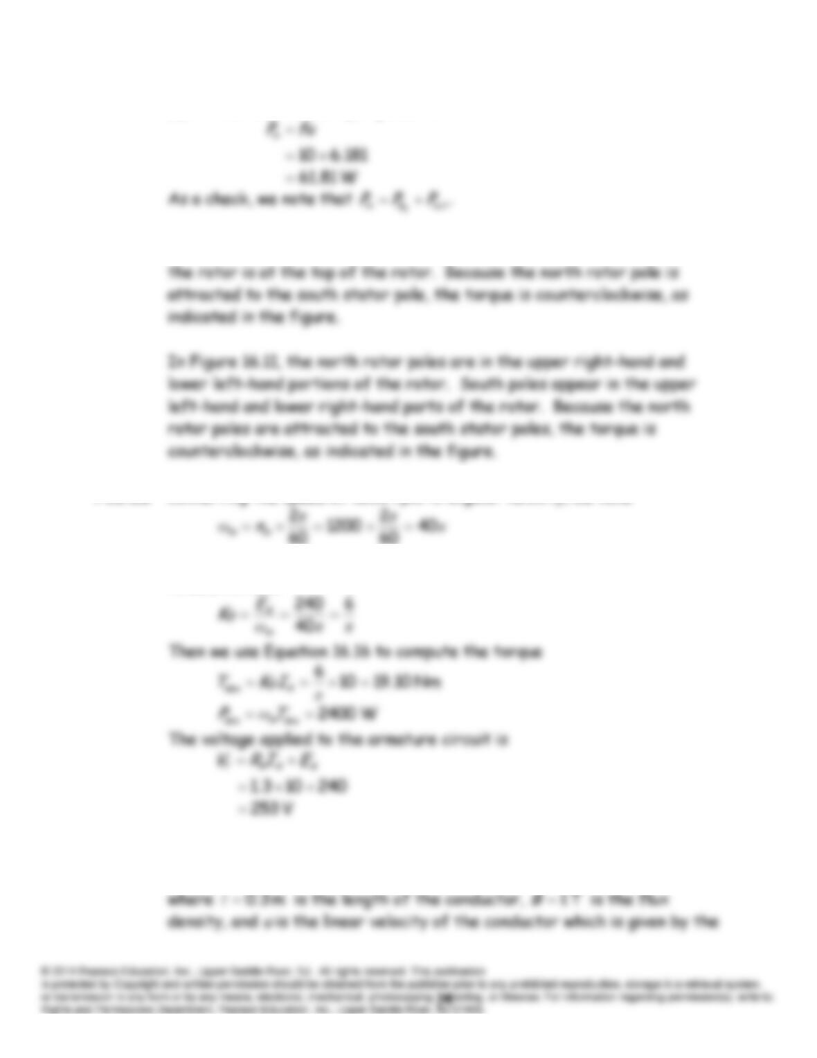
(c) The mechanical input power is
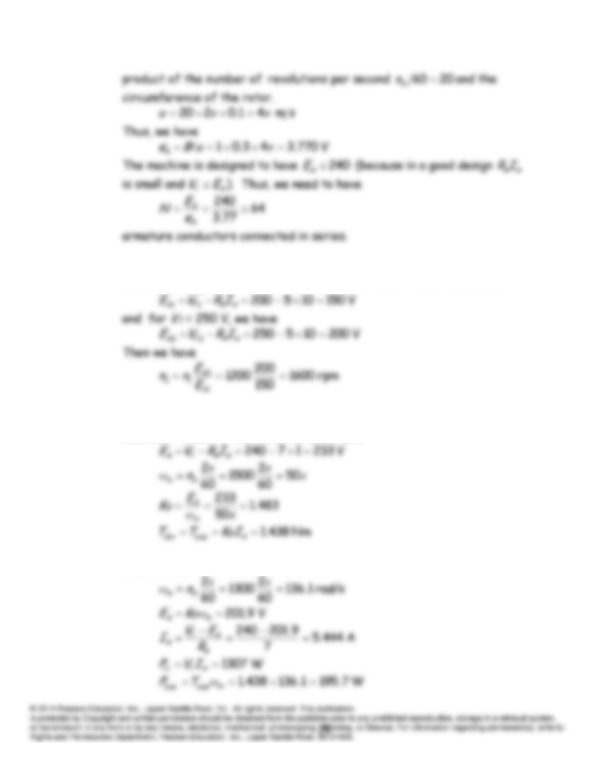
P16.27* Using the right-hand rule we see that in Figure 16.10, the north pole of
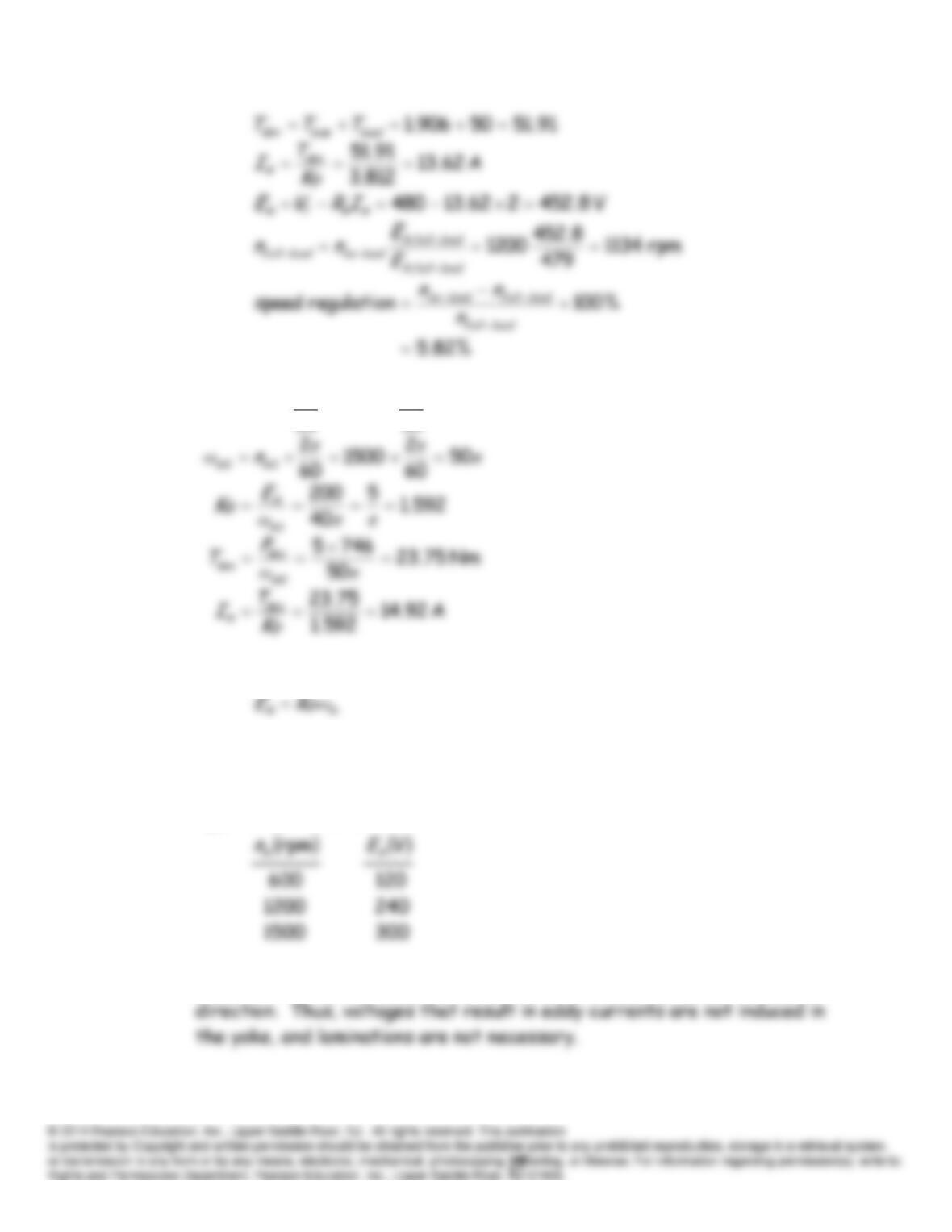
P16.28* Converting the speed of 1200 rpm to angular velocity, we have
Solving Equation 16.15 for the machine constant
φ
K
and substituting
values, we have
P16.29* The voltage induced in each armature conductor is given by
uBeA
P16.30* Because the field current is constant so is
K
. Then because the
developed torque is constant,
IA
is constant. For
VT
= 200 V, we have
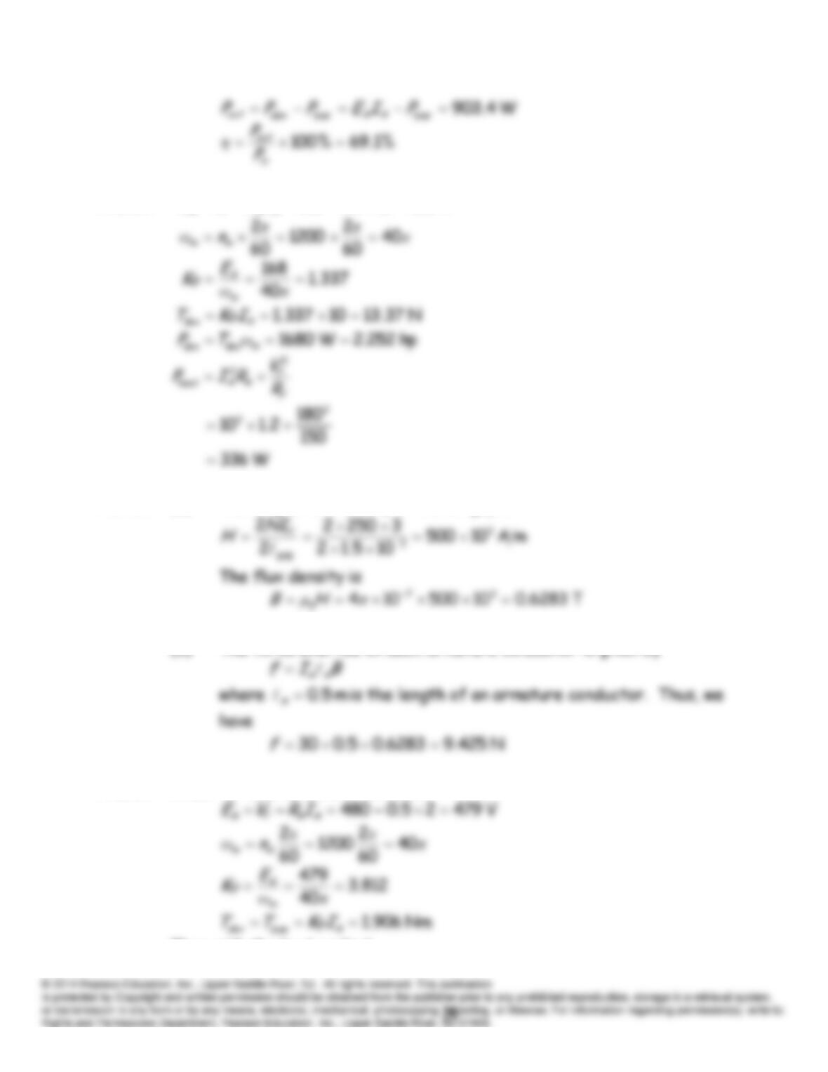
P16.31 For a permanent-magnet motor there are no field losses and
K
is
constant. Under no-load conditions, we have
Under loaded conditions, we have
P16.32
V 168102.1180
AA
T
AIRVE
P16.33 (a) The magnetic intensity in the air gap is
(b) The force exerted on each armature conductor is given by
P16.34 Under no-load conditions we have
Then with the load applied:
P16.35
π
ππ
ω40
60
2
1200
60
2
11
mm n
P16.36 Equation 16.15 states
With constant field current, the magnetic flux
φ
is constant. Therefore,
the back emf
EA
is proportional to machine speed
m
ω
(or equivalently to
m
n
). Thus, we have
P16.37 The magnetic field in the yoke is nearly constant in magnitude and
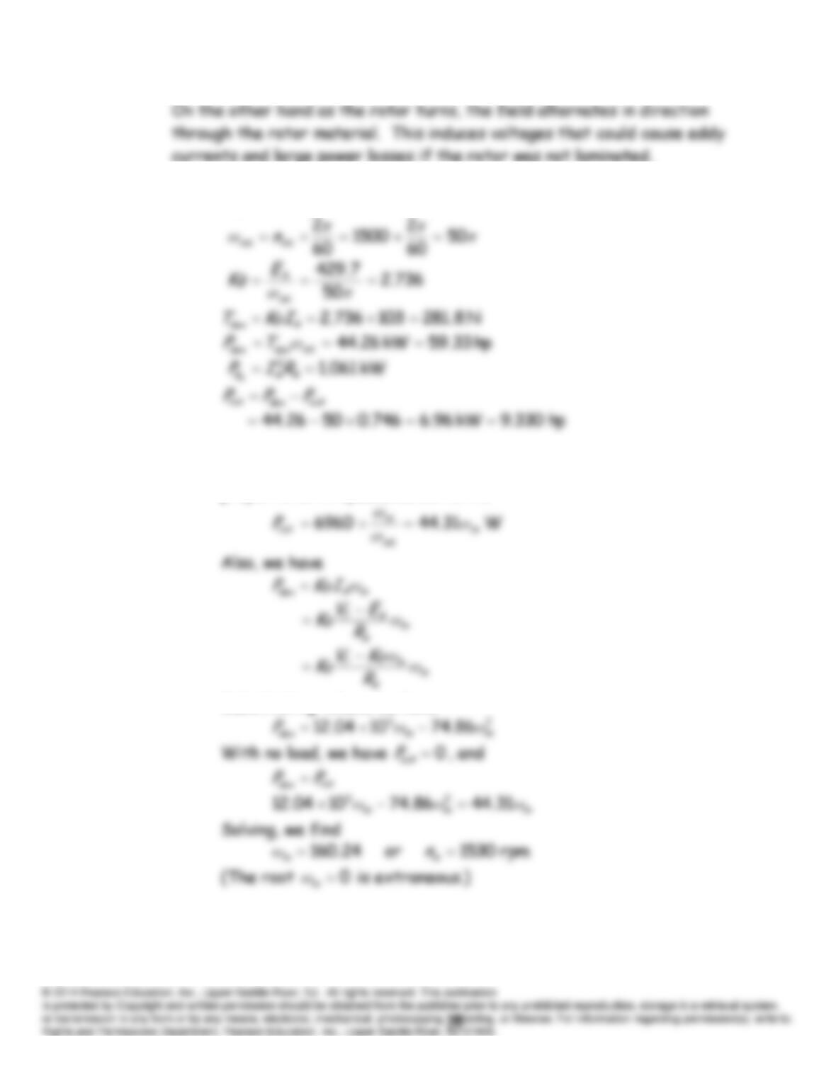
P16.38* (a)
V 7.4291031.0440
AA
T
AIRVE
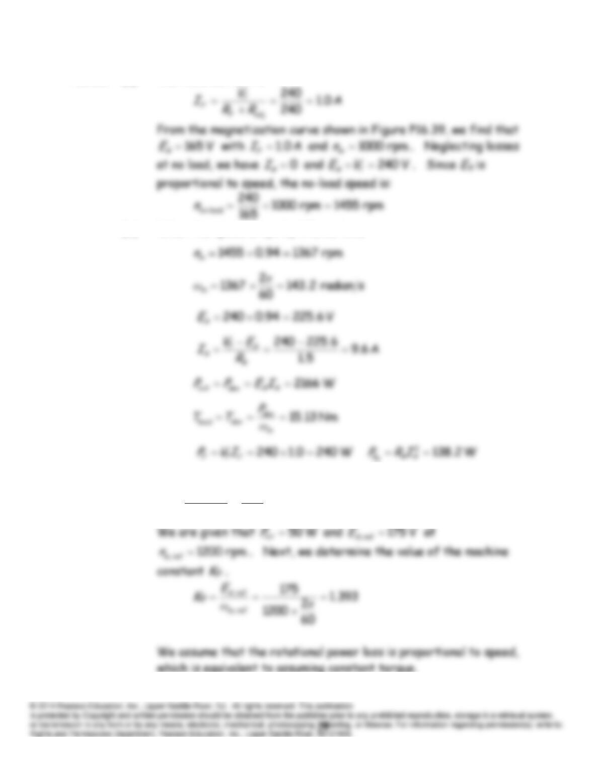
(b) Since we are assuming that the rotational power loss is
proportional to speed, we can write:
Substituting values, we have
P16.39* (a) The field current is
(b) When the speed drops by 6%, we have
P16.40* (a)
A 0.1
200
200
adj
RR
V
I
F
T
F