CHAPTER 15
Exercises
E15.1 If one grasps the wire with the right hand and with the thumb pointing
E15.2 If one places the fingers of the right hand on the periphery of the clock
E15.5 (a)
mWb 927.3)05.0(5.0 22 ππφ
rBBA
20104
4
7
π
μ
I
E15.7 By Ampère’s law, the integral equals the sum of the currents flowing
through the surface bounded by the path. The reference direction for
E15.8 Refer to Figure 15.9 in the book. Conceptually the left-hand wire
produces a field in the region surrounding it given by
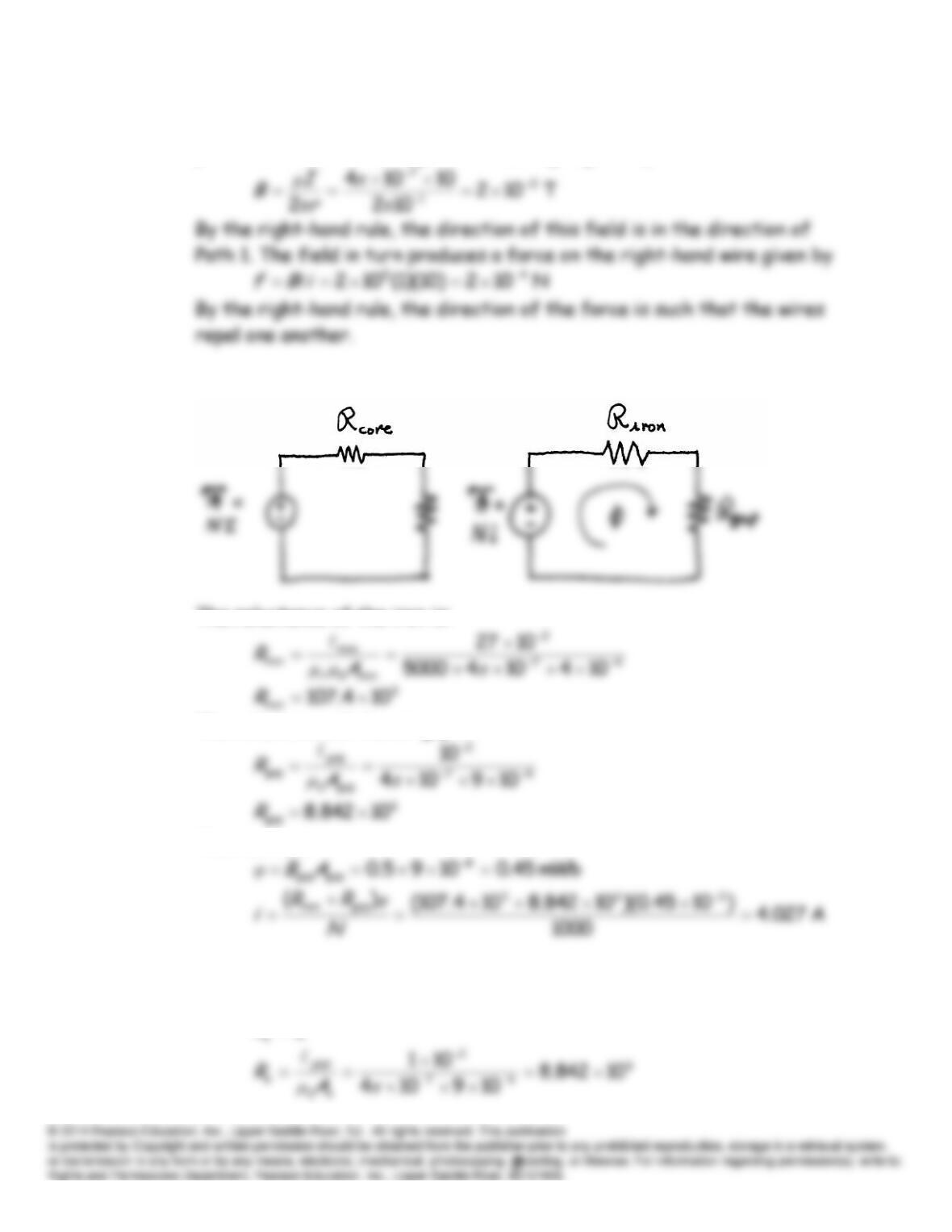
E15.9 The magnetic circuit is:
The reluctance of the iron is:
The reluctance of the air gap is:
Then we have
E15.10 Refer to Example 15.6 in the book. Neglecting the reluctance of the iron,
we have:
0
R
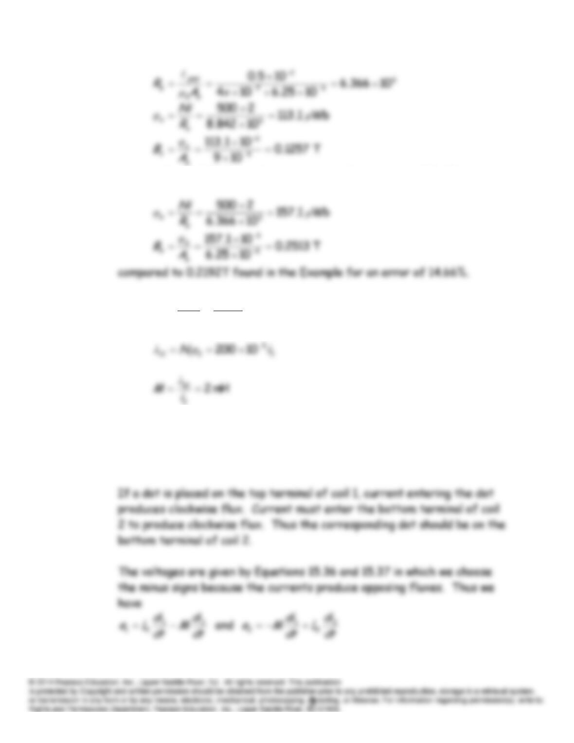
compared to 0.1123 T found in the example for an error of 11.9%.
E15.11
2
5
7
222
2102
10
200
i
i
R
iN
φ
E15.12 By the right-hand rule, clockwise flux is produced by
i
1 and
counterclockwise flux is produced by
i
2. Thus the currents produce
opposing fluxes.
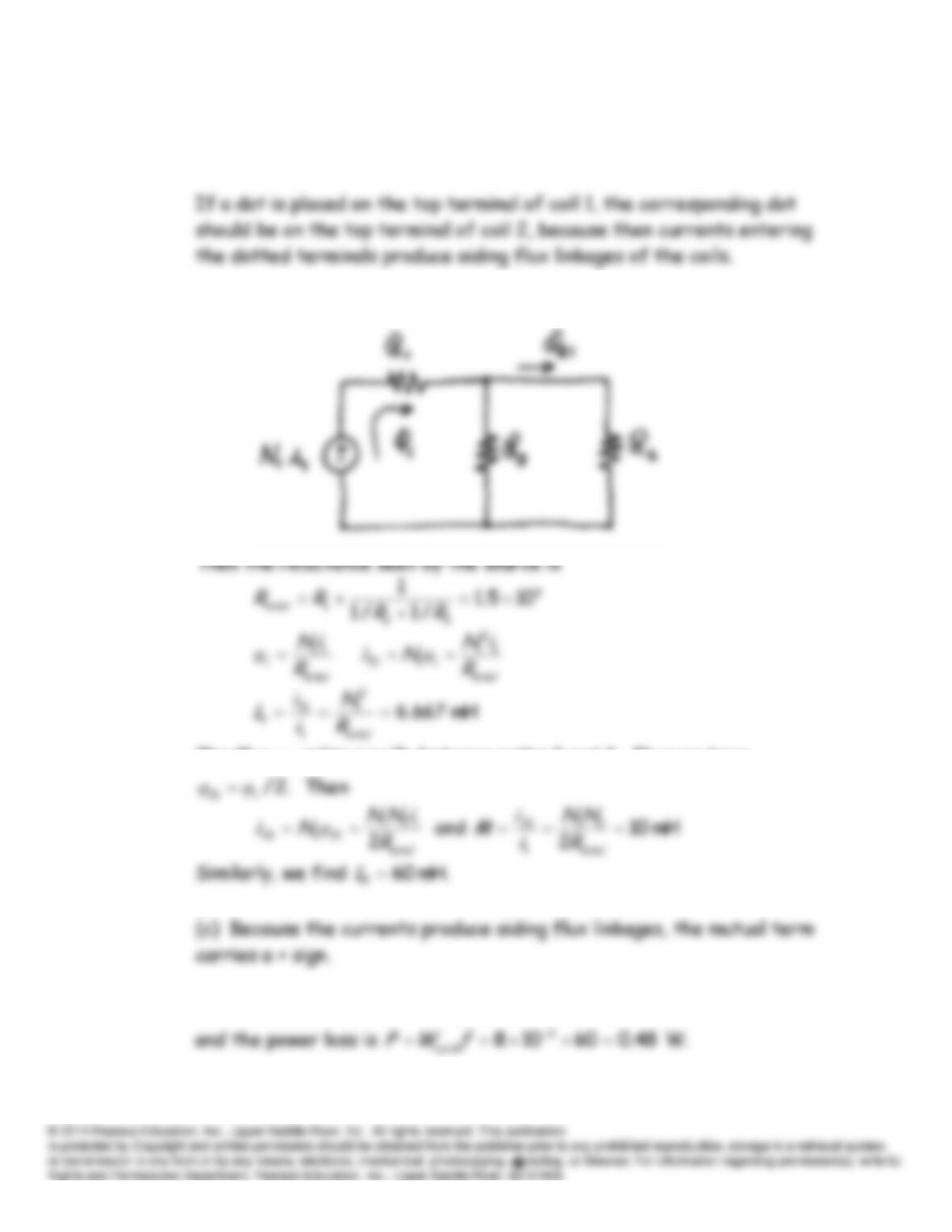
E15.13 (a) Using the right-hand rule, we find that the fluxes produced by
i
1 and
i
2 aid in path 1, aid in path 2, and oppose in path 3.
(b) For
i
2 = 0, the magnetic circuit is:
The flux
1
φ
splits equally between paths 2 and 3. Thus we have
E15.14 The energy lost per cycle is
mJ 8)m 10200()J/m 40(363
cycle
W
,
1000 3
NI
E15.16 Refer to Figure 15.26c in the book.
0100
V
s
E15.17
Ω 25400
4
12
2
1
LL R
N
N
R
E15.18 For maximum power transfer, we need
However we have
Thus we have
Problems
P15.1 According to Faraday’s law of magnetic induction, a voltage is induced in a
coil equal to the time rate of change of flux linkages.
P15.2 Ampère’s law states that the integral of magnetic field intensity around a
closed path is equal to the sum of the currents flowing through any
P15.3 (a) If one grasps a current-carrying wire using the right hand with the
thumb pointing in the direction of the current, the fingers encircle the
P15.5* By Lenz’s law, the polarity of the induced voltage is such that the current
flowing through a resistance placed across the terminals of the coil tends
10104
5
7
I
Some ways to reduce the effects of electrical wiring on a navigation
P15.7* Equation 15.4 in the text states:
P15.8 For any closed path inside the pipe, we have
P15.9 Each part of the loop may experience force due to the field of another
P15.10 Rearranging Equation 15.2, we have
)sin(
qu
f
B
. However, the units of
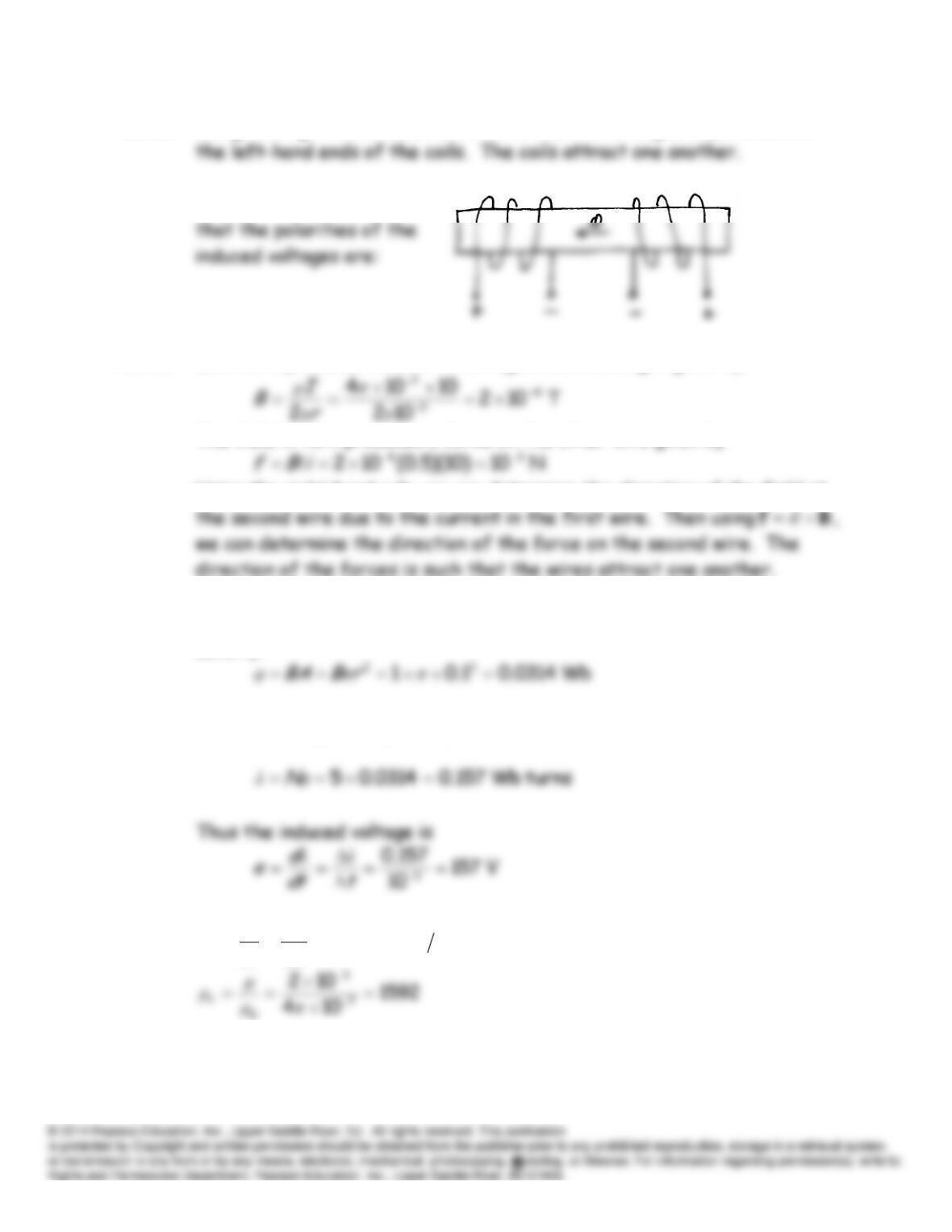
P15.11 Using the right-hand rule, we find that the north magnetic poles are at
P15.12 Using Lenz’s law, we find
P15.13 Each wire produces a field in the region surrounding it given by
The field in turn produces a force on the other wire given by
Using the right hand rule, we can determine the direction of the field at
P15.14* The flux linking the coil is the product of the coil area and the flux
density.
The flux linkages are given by:
P15.15*
AmWb 102
50
1.0 3
H
B
μ
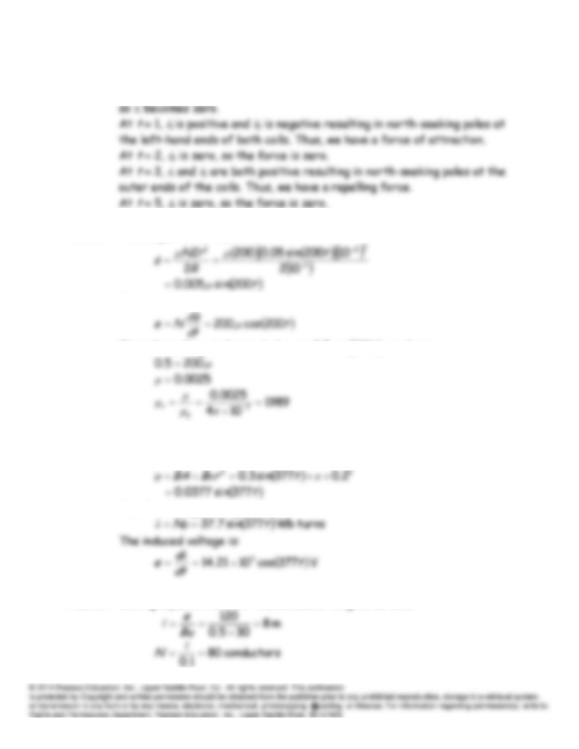
P15.16 Between
t
0 and
t
4,
i
2 is increasing and voltage is induced in coil 1
such that
i
1 is positive. After
t
4,
i
2 and the magnetic field are constant
P15.17 From Equation 15.18, we have:
However,
Since the voltage is known to be
te
200cos5.0
, we have:
P15.18 The flux linking the coil is the product of the coil area and the flux
density.
The flux linkages are given by:
P15.19 Solving Equation 15.9 for the conductor length, we have:
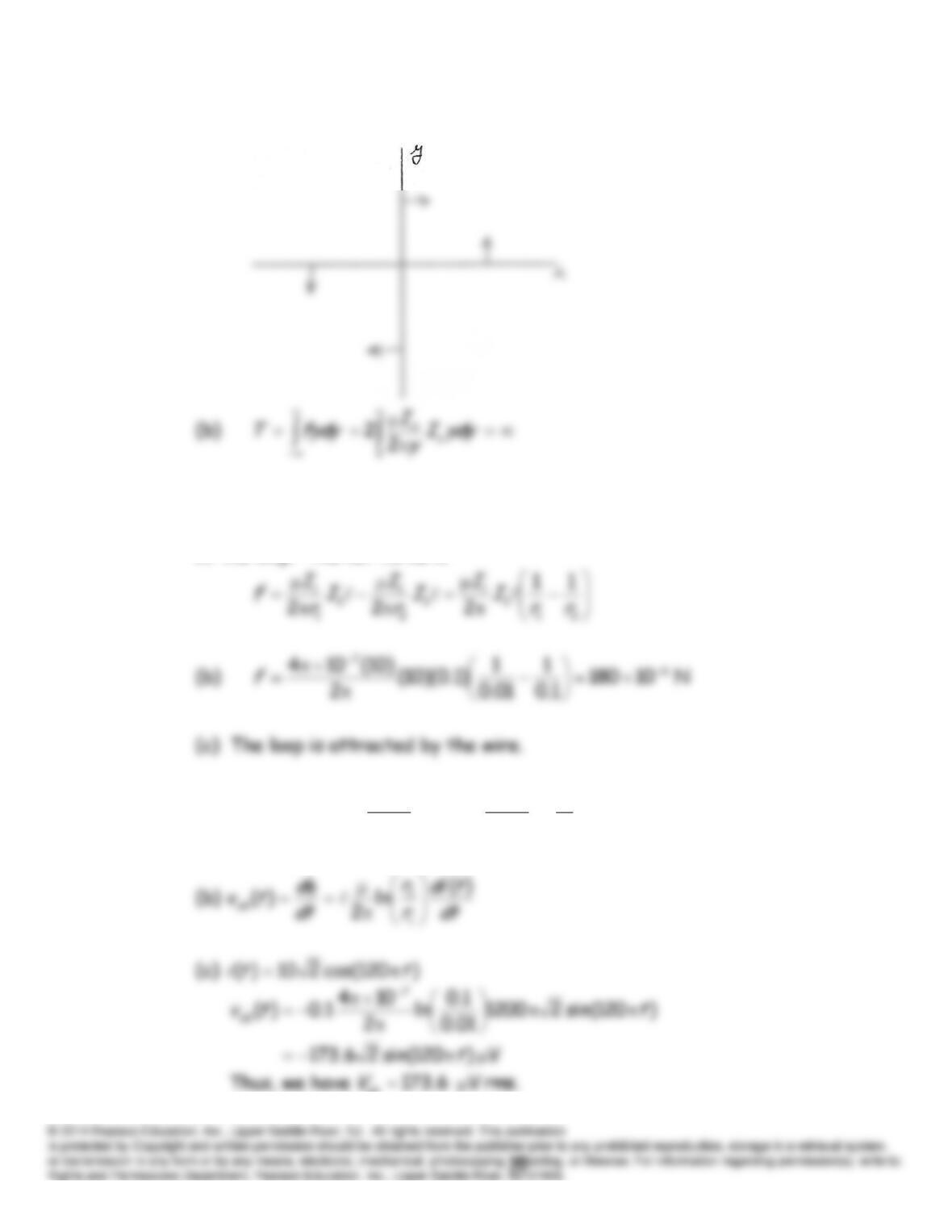
P15.20 (a) The forces are indicated
P15.21 (a) Equal and opposite forces are exerted on the top and bottom sides of
the loop. Thus, we only need to consider the forces on the vertical sides
of the loop. The net force is
P15.22 (a)
1
2
0
ln
2
)(
2
)(
2
1
r
r
ti
drdz
r
ti
r
r
AdAB
ab
P15.23
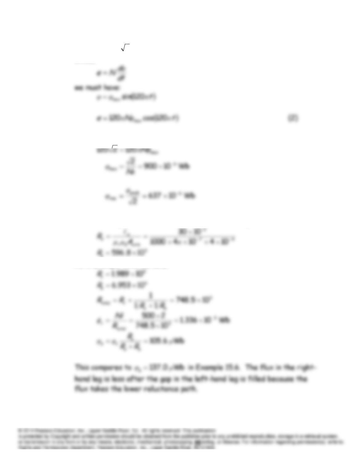
te
π120cos2120
(1)
Since,
Equating the amplitudes of the expressions given in (1) and (2), we have:
P15.24* Without the gap, the reluctance of the left-hand leg becomes:
As in Example 15.6, we have:
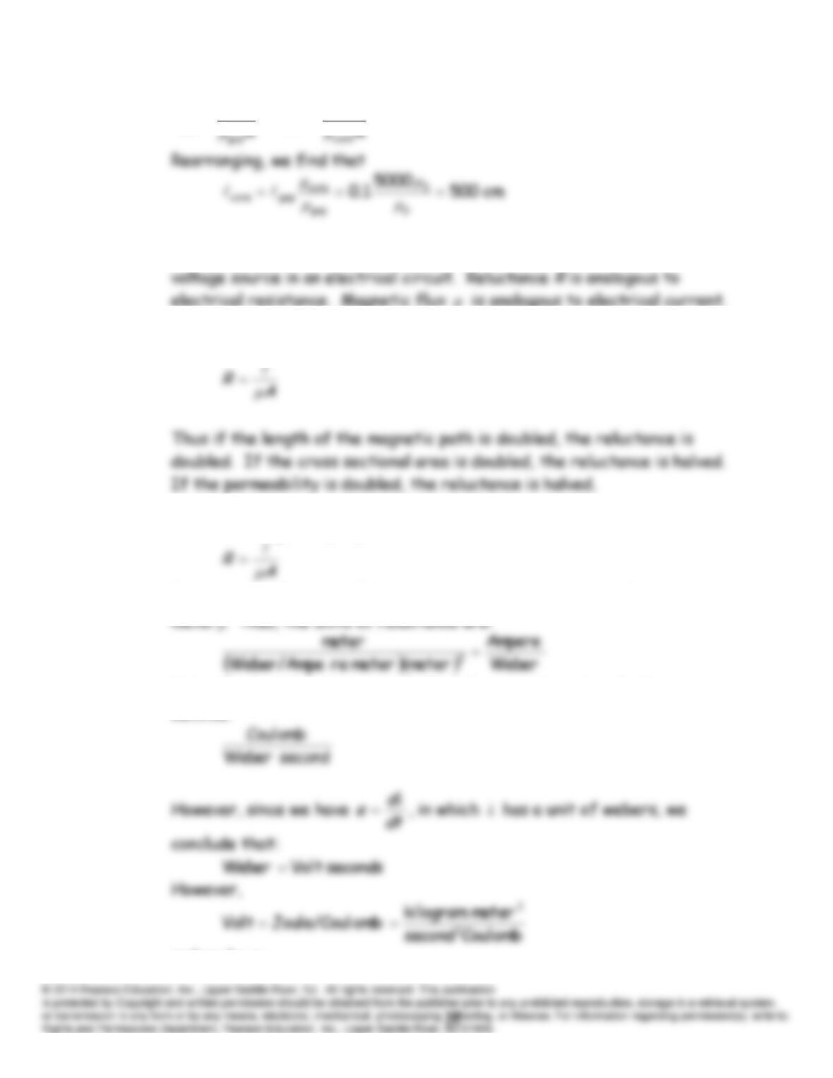
P15.25*
R
R
core
core
gap
gap μμ
P15.26* Magnetomotive force
NiF
in a magnetic circuit is analogous to a
φ
P15.27 Reluctance is given by Equation 15.21:
P15.28 Reluctance is given by Equation 15.21:
Furthermore, Equation 15.11 gives the units of
μ
as Weber/(Ampere
Using the fact that Ampere = Coulomb/second, the units of reluctance
become:
and we have:
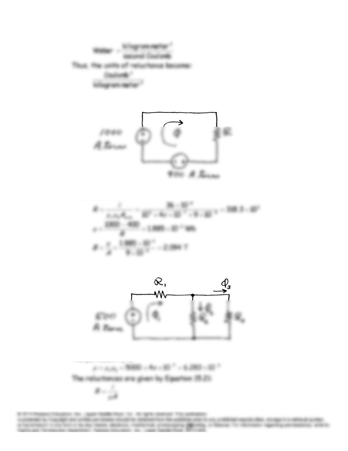
P15.29 The magnetic circuit is:
The reluctance is:
P15.30 The magnetic circuit is:
The permeability is:
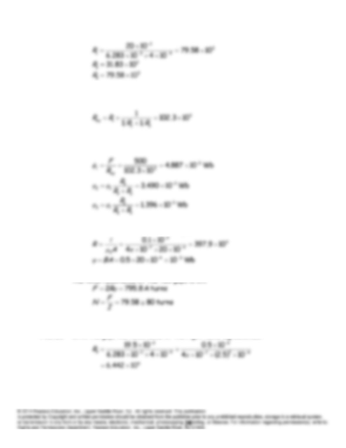
The equivalent reluctance seen by the source is:
The fluxes are:
P15.31 The reluctance of each of the two gaps is:
The total reluctance of the two gaps is 2
R
.
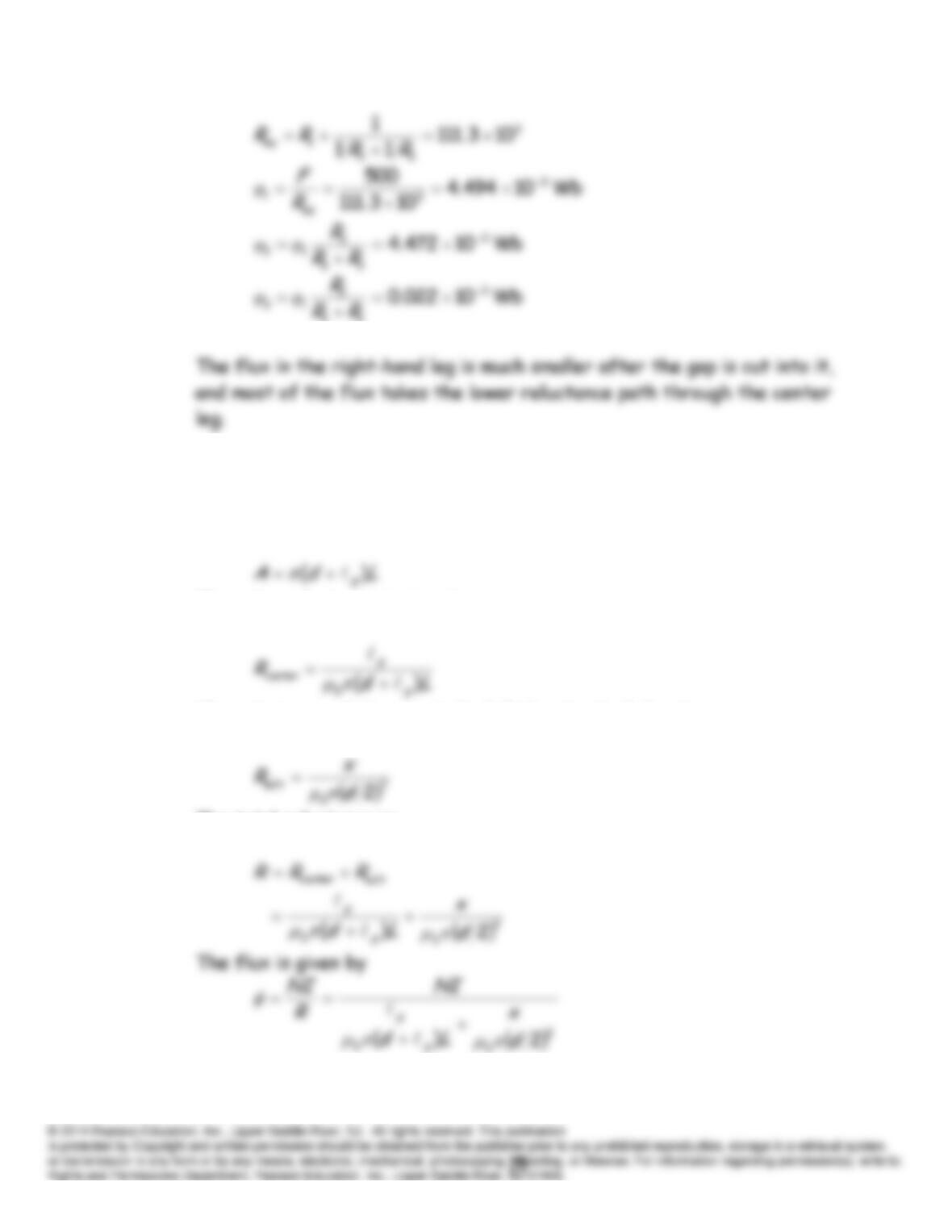
P15.32 With the gap, the reluctance of the right-hand leg becomes:
The equivalent reluctance seen by the source is:
23
P15.33* The flux must pass through two gaps, one at the left-hand of the end of
the plunger and the other in the center of the plunger. The area of the
gap surrounding the center of the plunger is approximately:
Thus, the reluctance is given by:
The reluctance of the gap at the left-hand end of the plunger is:
The total reluctance is:
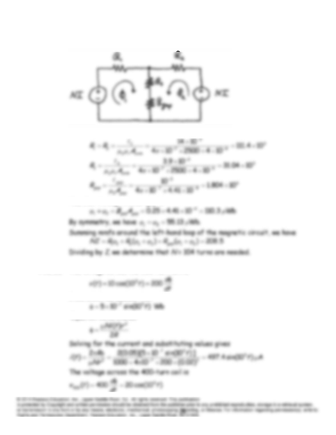
P15.34 The magnetic circuit is:
We have
The flux through the air gap is
P15.35 The voltage across the 200-turn coil is
from which we deduce that
Equation 15.18 states
dt
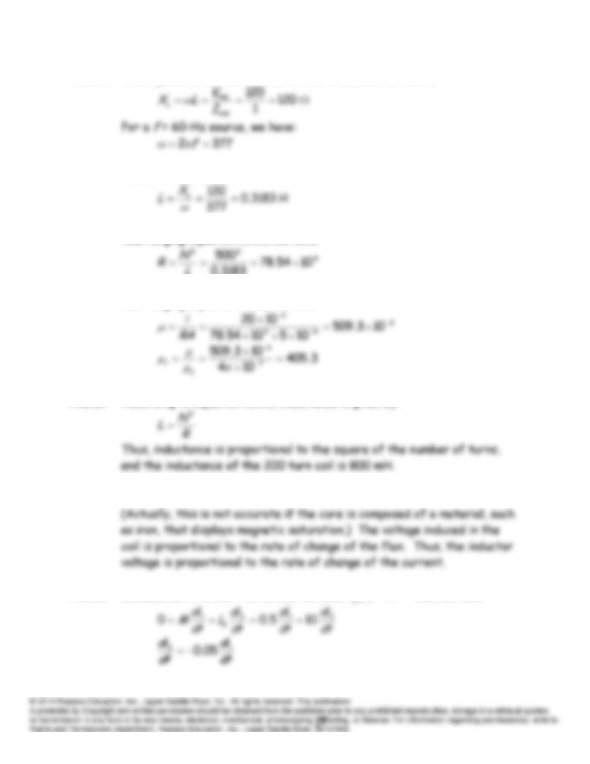
P15.36* The impedance of the inductance to a sinusoidal current is:
Thus, the inductance is
Rearranging Equation 15.25, we have:
3183.0
L
Rearranging Equation 15.21, we have:
P15.37* According to Equation 15.25, inductance is given by:
P15.38 The magnetic flux linking a coil is proportional to the current in the coil.
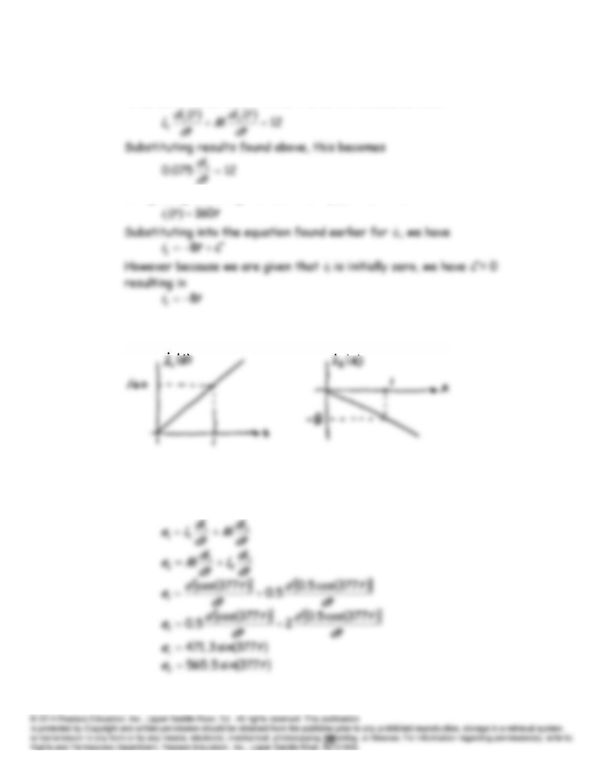
P15.39* Because coil 2 is short circuited, we have
0
tv
. Thus, we have
which implies that
,05.0 12
Cii
in which
C
is a constant of integration
to be determined later. After the switch closes, we have
Integrating and using the fact that
00
1
i
, we have
The sketches are:
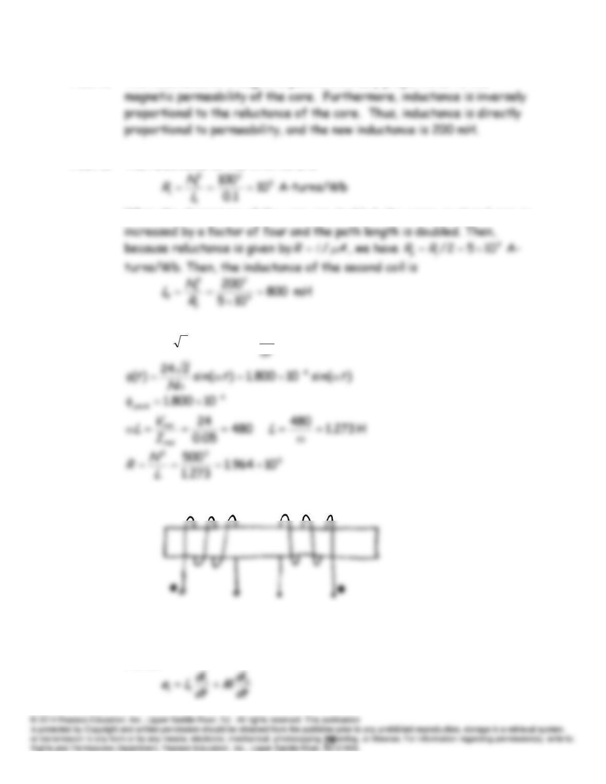
P15.40* The voltages are given by Equations 15.36 and 15.37. We select the +
signs because both currents enter dotted terminals and produce aiding
fluxes.
P15.41 The reluctance of a magnetic path is inversely proportional to the
P15.42 The reluctance of the first core is
When the dimensions of the core are doubled, the cross-sectional area is
P15.43
d
Nttv
)cos(224)(
P15.44 The coil and dots are:
P15.45 The voltages are given by Equations 15.36 and 15.37. We select the +
signs because both currents enter dotted terminals and produce aiding
fluxes.