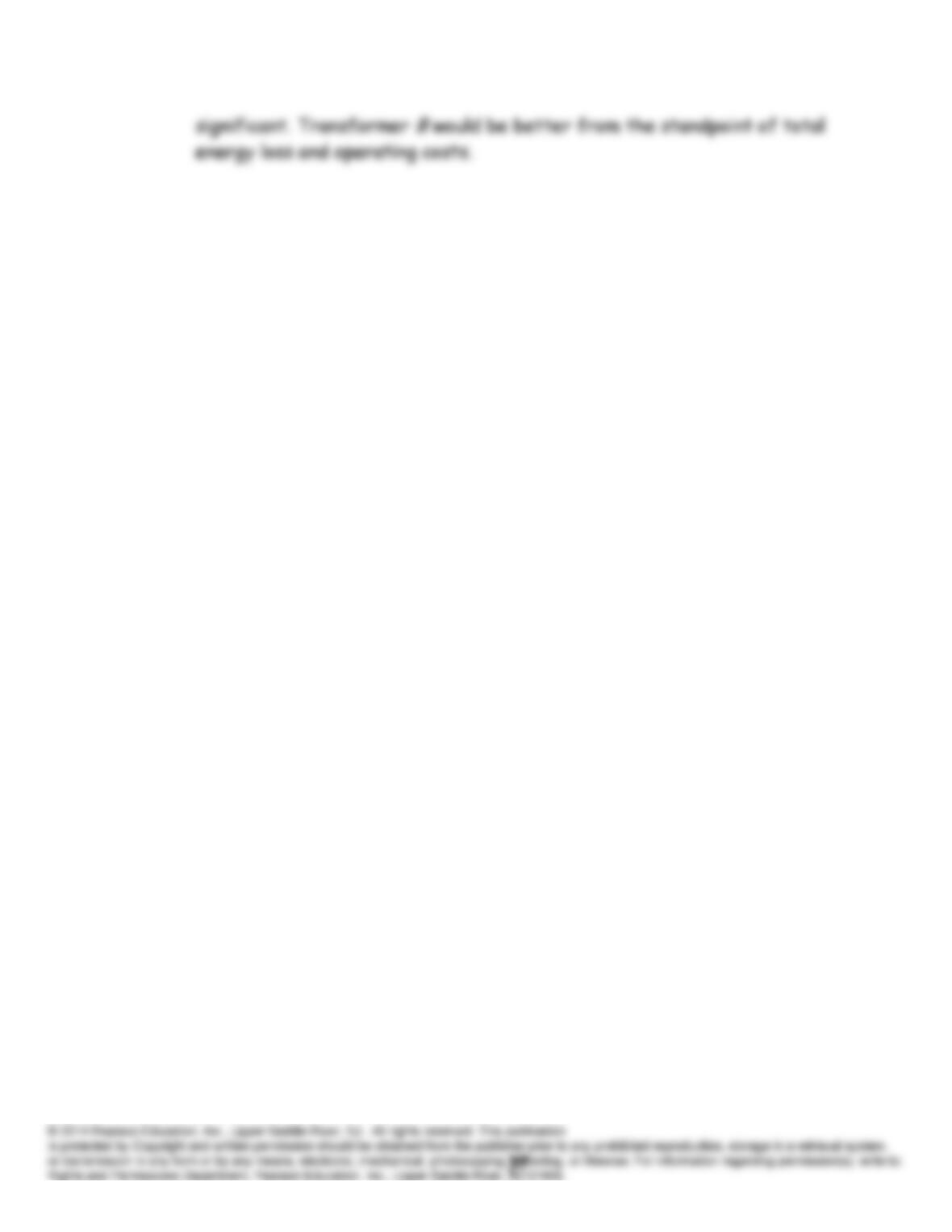
dt
di
L
dt
di
Me
2
2
1
2
P15.46 According to Equations 15.34 and 15.35, we have
2111
MiiL
λ
When both currents enter dotted terminals, the fluxes aid and we use
the + signs.
On the other hand, when one current enters a dotted terminal and the
other enters an undotted terminal, the fluxes oppose one another, and we
use the – signs.
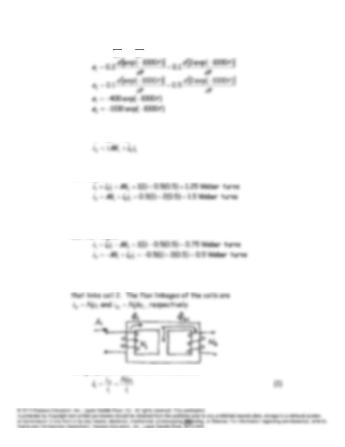
P15.47 Consider the coils shown below with current flowing only in winding 1.
1
φ
is the flux produced by the current in coil 1, and
121 φφ
k
is the flux
Using Equations 15.29 and 15.31, we have
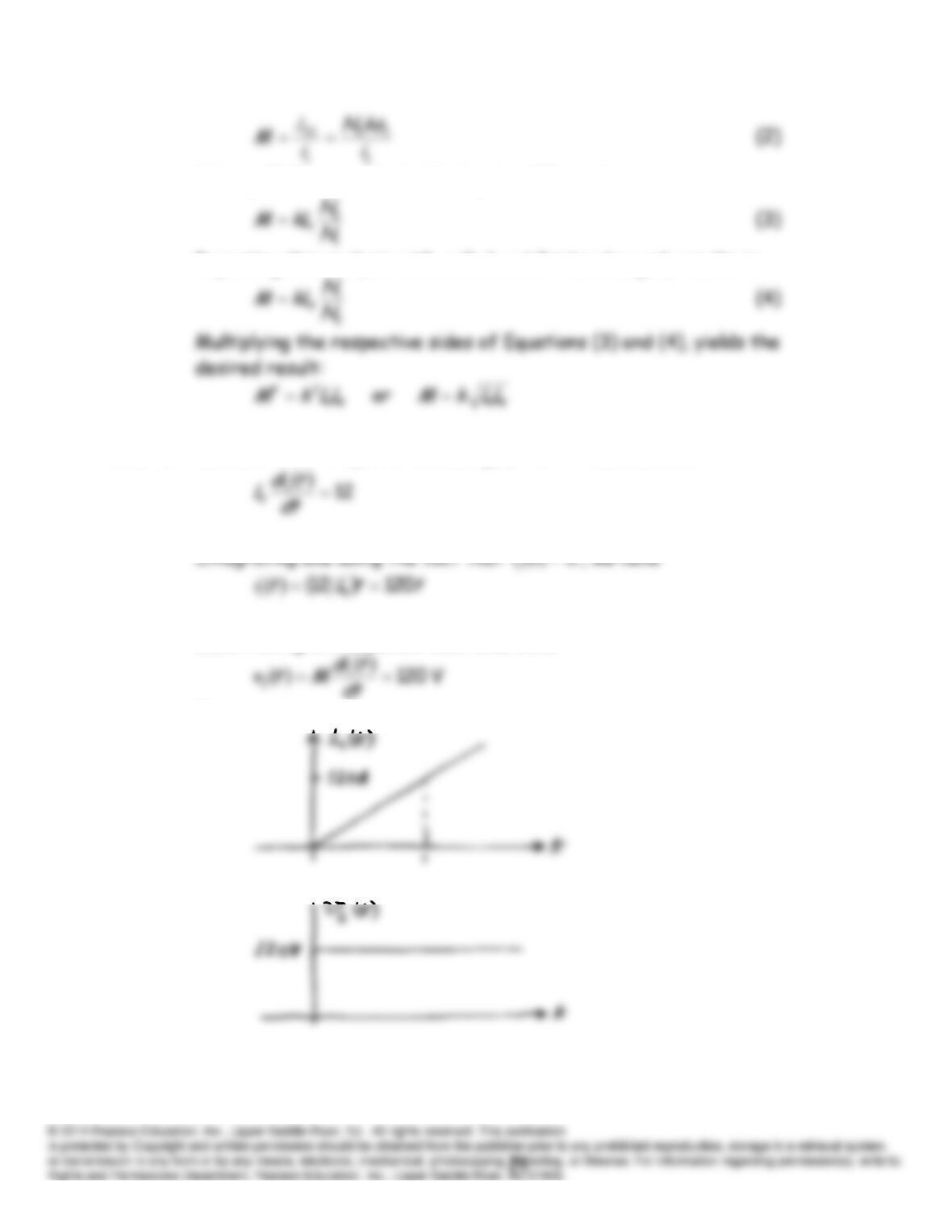
Solving (1) for
1
i
and substituting into (2), we have:
Repeating this analysis with coils 1 and 2 interchanged, results in:
P15.48 Because coil 2 is open circuited,
0
2
ti
. Thus, we have
Substituting into Equation 15.37, we have:
The sketches are:
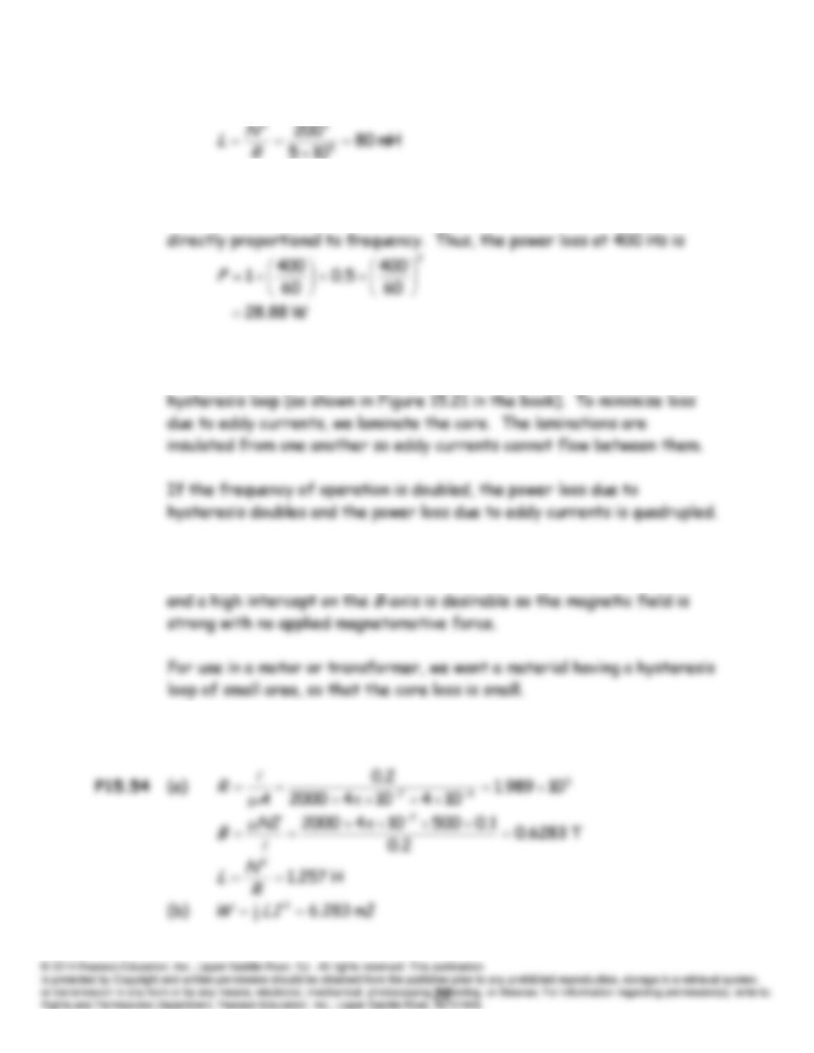
P15.49 According to Equation 15.25, inductance is given by:
P15.50* Assuming constant peak flux density, power loss due to eddy currents
increases with the square of frequency. Power loss due to hysteresis is
P15.51* Two causes of core loss are hysteresis and eddy currents. To minimize
loss due to hysteresis, we should select a material having a thin
P15.52 For use in a permanent magnet, a material with a broad hysteresis loop
P15.53 See Figure 15.18c in the book.
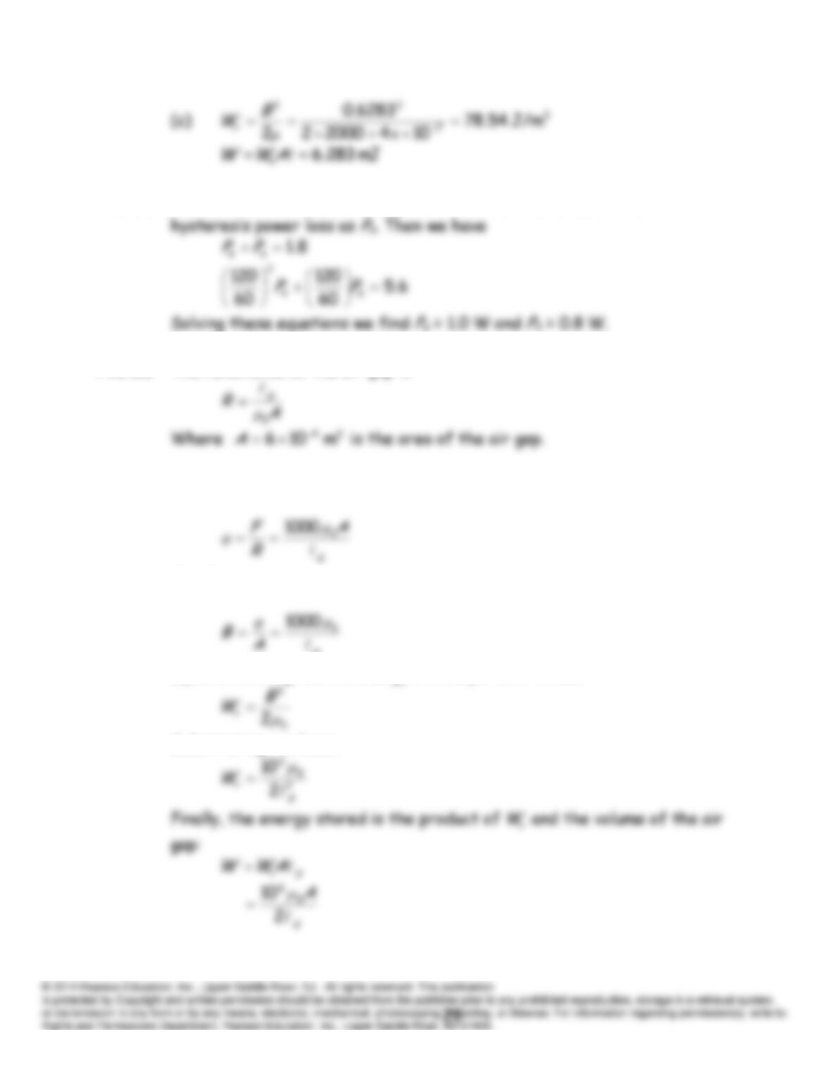
P15.55 We denote the eddy-current power loss at 60 Hz as
Pe
and the
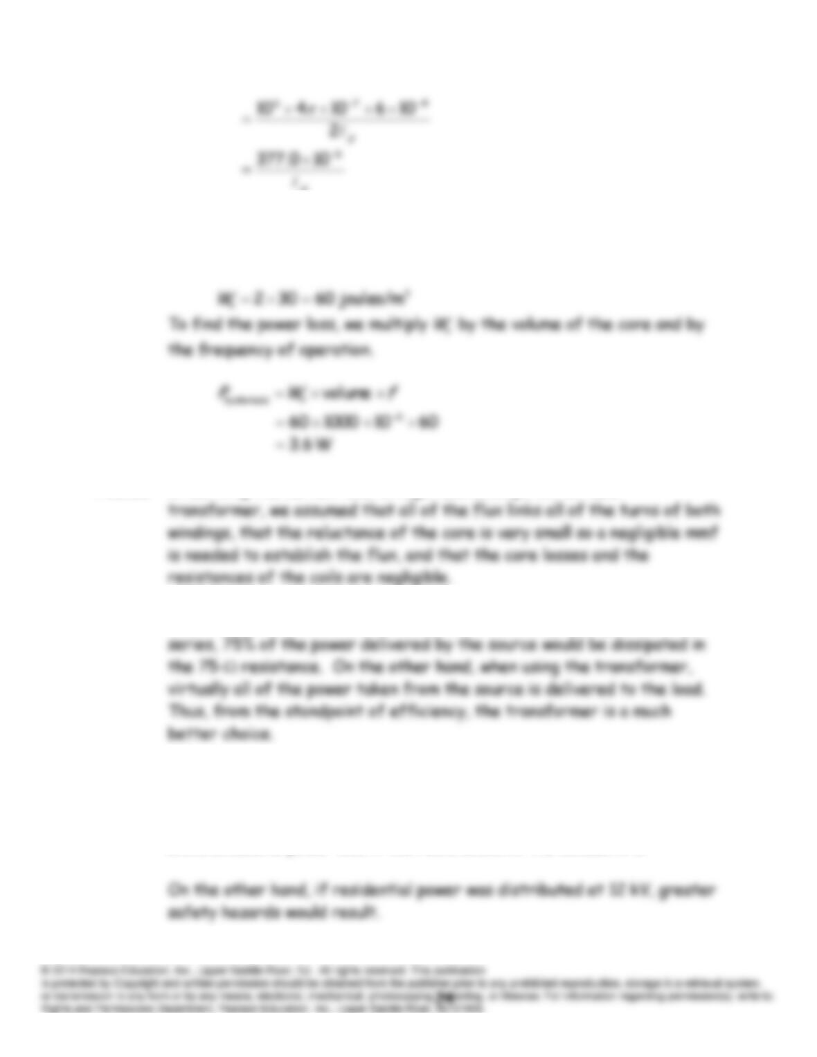
P15.56 The reluctance of the air gap is
The flux is given by:
The flux density is:
g
Equation 15.41 gives the energy stored per unit volume:
Substituting, we have:
g
P15.57 As indicated by Equation 15.40, the area enclosed by the hysteresis loop
is the energy dissipated per unit volume for each cycle. The area of the
hysteresis loop shown in Figure P15.54 is:
P15.58 In deriving the current and voltage relationships for an ideal
P15.59* If we tried to make the 25 load look like 100 by adding 75 in
P15.60* If residential power was distributed at 12 V (rather than 120 V) higher
currents (by an order of magnitude) would be required to deliver the
same amounts of power. This would require much larger wire sizes to
avoid excessive power loss in the resistances of the conductors.
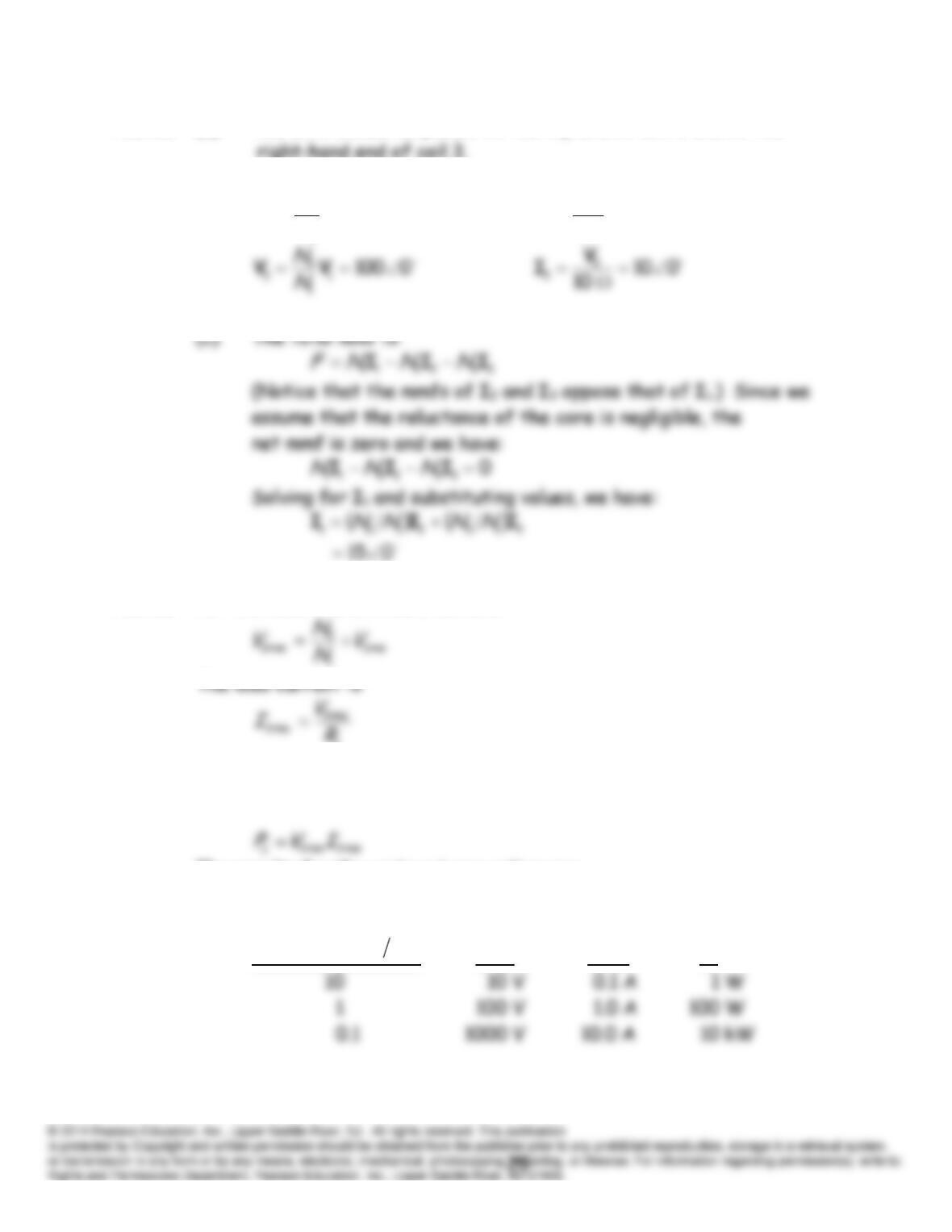
P15.61* (a) The dots should be placed on the top end of coil 2 and on the
right-hand end of coil 3.
(b)
050
1
1
2
2 VV
N
N
010
5
2
2
V
I
P15.62 For the ideal transformer, we have:
L
The load power is given by
The results for the various turns ratios are:
21
Ratio Turns
NN
2rms
V
rms2
I
L
P
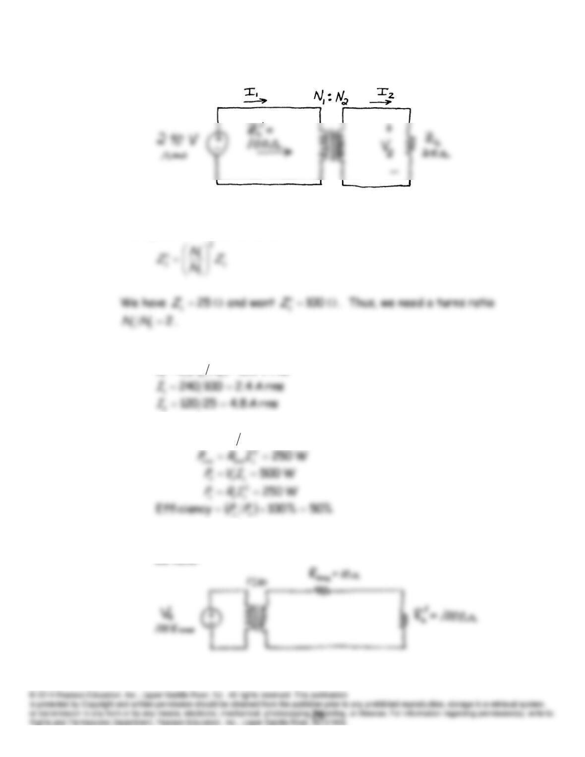
P15.63 The circuit is:
According to Equation 15.62, impedances are reflected to the primary by
the square of the turns ratio.
The secondary voltage and currents are:
rmsV 120
NNVV
P15.64 (a)
rms A 5
line
L
s
LRRVI
(b) Reflecting the load to the primary of the step-down transformer,
we have:
Then, reflecting both the load and line resistances to the primary
of the step-up transformer, we have:
P15.65 (a)
306
0400
(c)
1506
1I
180400
2V
P15.66 (a) The circuit reflected to the primary side is:
P15.67 (a) Let
N
1 = 200 turns and
N
2 = 300 turns (i.e.,
N
2 is the total number
(b) The net mmf is:
P15.68
40
L
R
L
P15.69 We have:
Dividing the respective sides of these equations, we obtain:
10
2
1
2
1
N
N
v
v
213 III
P15.70* The equivalent circuit of a real transformer is shown in Figure 15.28 in
P15.71* We follow the method of Example 15.13. The results are:
rms A 87.36333.8
2
I
2
2
21
2
1
2
loss
RIRI
R
V
P
c
s
Next, we can determine the no-load voltages. Under no-load conditions,
we have:
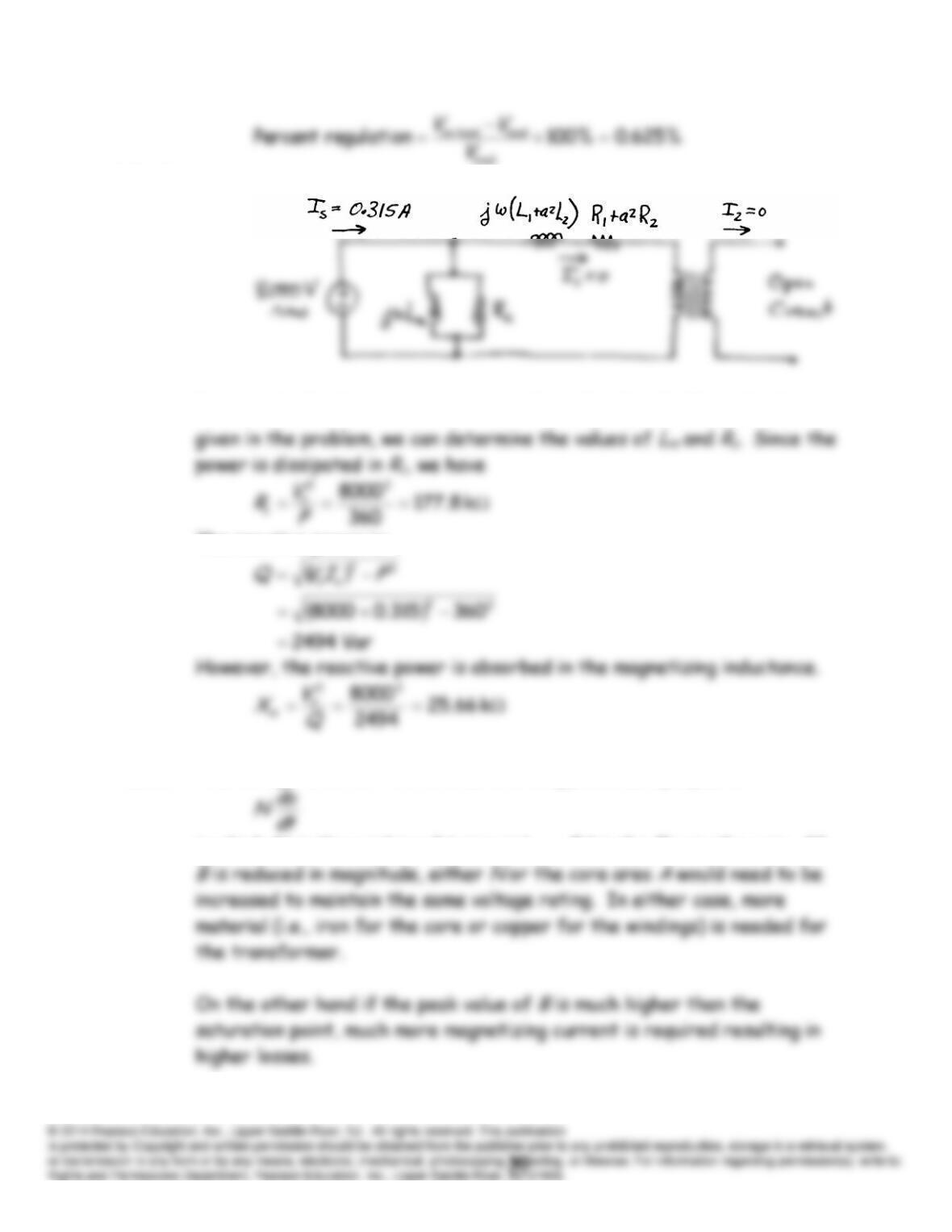
P15.72 The equivalent circuit is:
Because the load is an open circuit, we have
0
21 II
. From the data
The reactive power is:
P15.73* The voltage across a transformer coil is approximately equal to
in which
N
is the number of turns and
BA
is the flux in the core. If
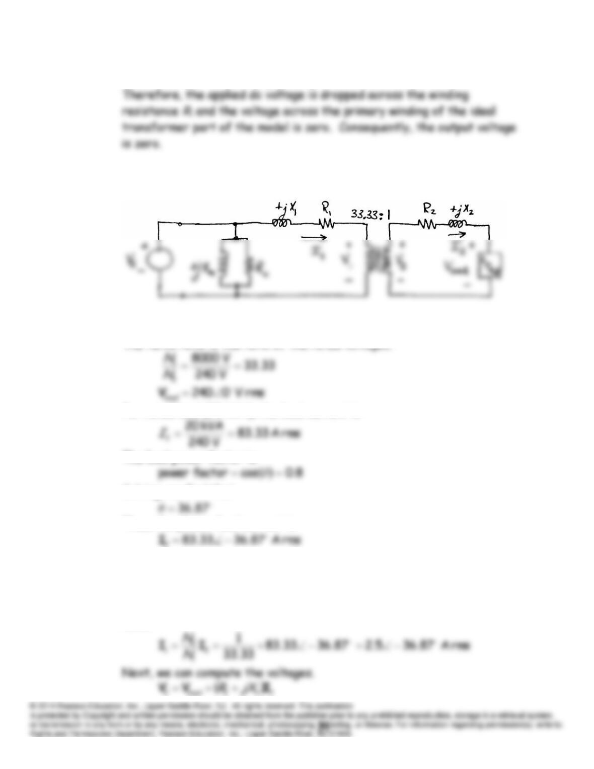
P15.74 In dc steady state, the magnetizing inductance
Lm
acts as a short circuit.
P15.75 We follow the method of Example 15.13. The equivalent circuit is:
The turns ratio is the ratio of the rated voltages.
For rated load (20 kVA), the load current is:
The load power factor is:
Solving, we find that
Thus, the phasor load current is:
2
where the phase angle is negative because the load was stated to have a
lagging power factor.
The primary current is related to the secondary current by the turns
ratio.
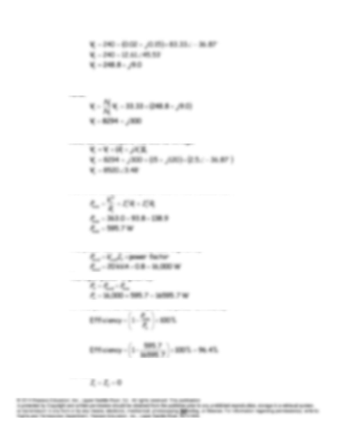
The primary voltage is related to the secondary voltage by the turns
Now, we can compute the source voltage.
Next, we compute the power loss in the transformer.
The power delivered to the load is given by:
The input power is given by:
At this point, we can compute the power efficiency.
Next, we can determine the no-load voltages. Under no-load conditions,
we have:
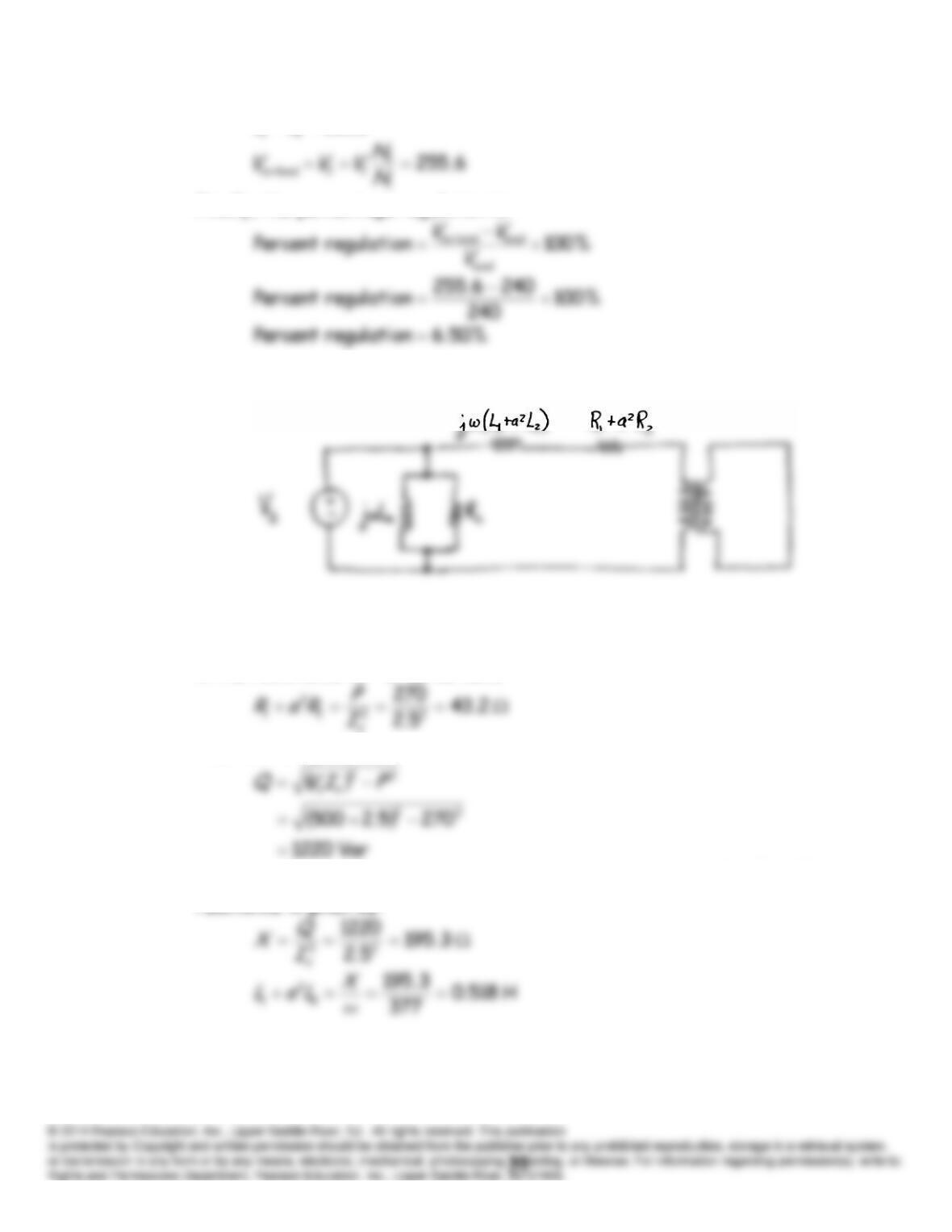
8520
VV
Finally, the percentage regulation is:
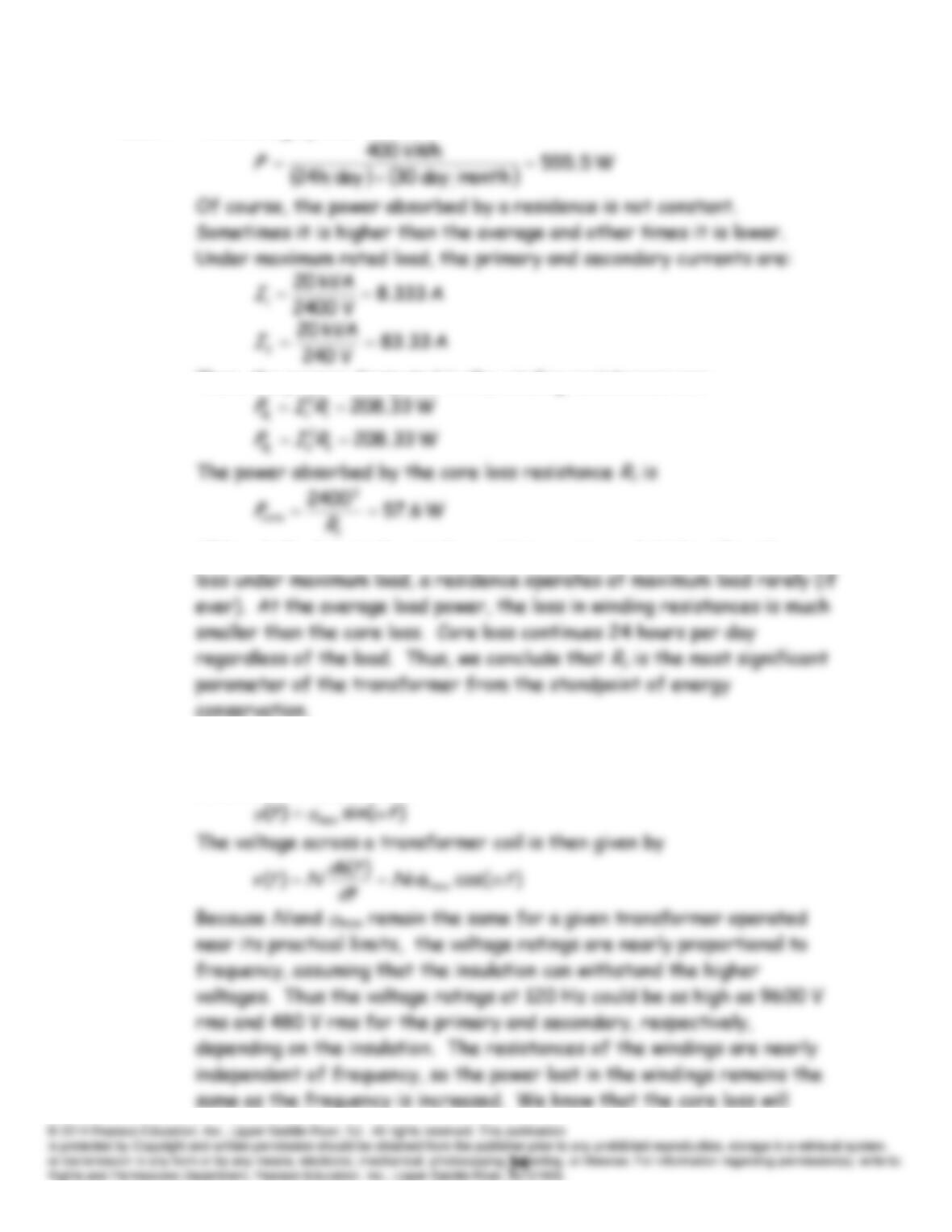
P15.76 The equivalent circuit is:
With a short-circuit load and rated current,
Vs
is very small and the
currents through
Rc
and
Lm
are negligible. Since the power is dissipated
in the resistance
R
1 +
a
2
R
2, we have:
The reactive power is:
However, the reactive power is absorbed in the inductance
2
2
1
LaL
. The
reactance is given by:
P15.77 The average power level is
Then, the powers dissipated in the winding resistances are:
Although the loss in the winding resistances is much higher than the core
P15.78 For operation with sinusoidal voltages, the flux in the core must be
sinusoidal. Thus, we have
Practice Test
T15.1 (a) We have
N 72.0)90sin(3.0)2.0(12)sin(
Bif
. (
is the angle
T15.4 (a) The magnetic circuit is:
The permeability of the core is:
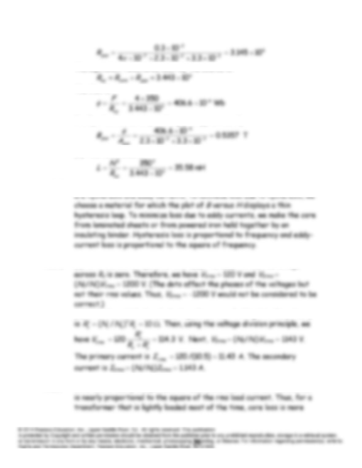
The equivalent reluctance seen by the source is:
The flux is :
Finally, the flux density in the gap is approximately
gap
(b) The inductance is
T15.5 The two mechanisms by which power is converted to heat in an iron core
T15.6 (a) With the switch open, we have
I
firm 0,
I
1rms 0 and the voltage
(b) With the switch closed, the impedance seen looking into the primary
T15.7 Core loss is nearly independent of load, while loss in the coil resistances