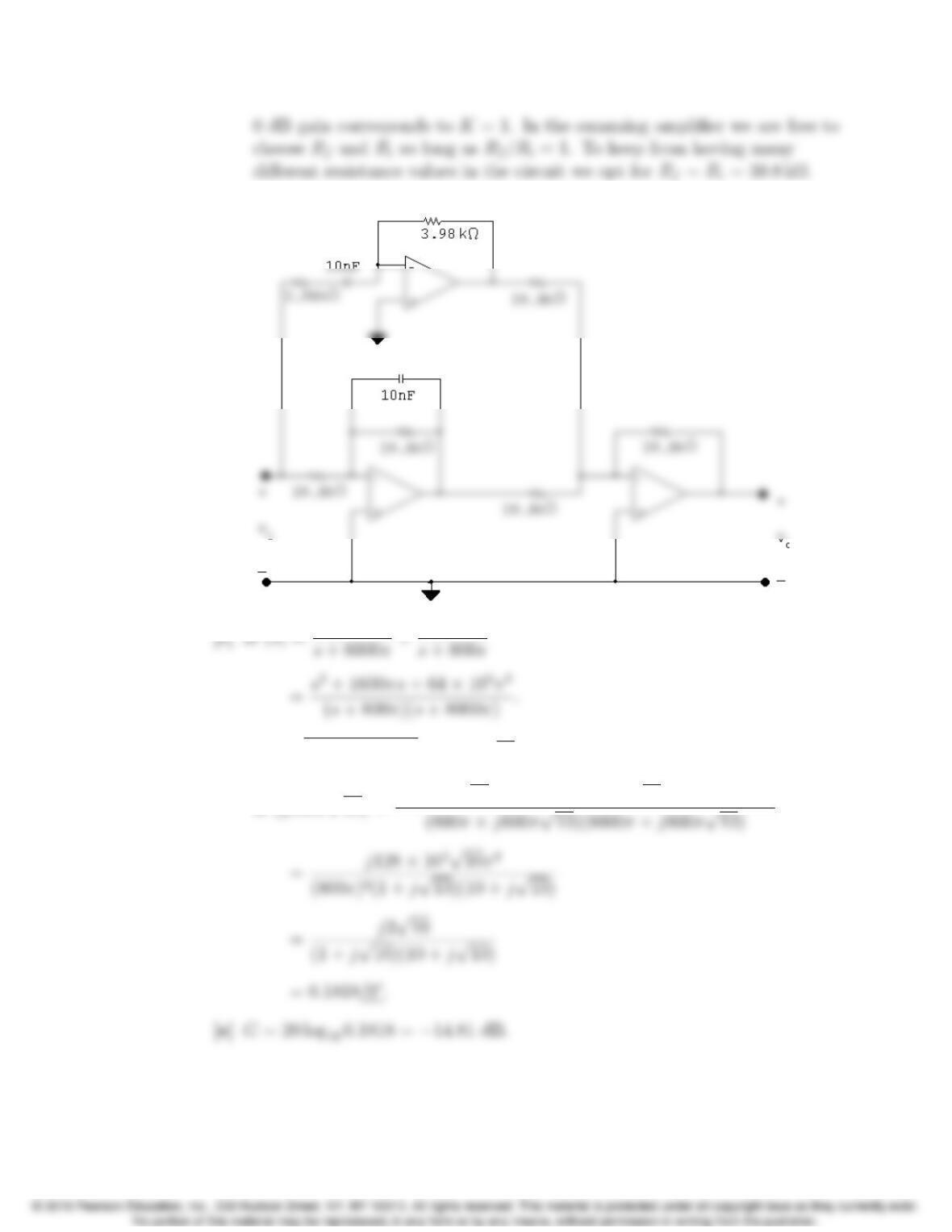
Problems 15–21
[b]
[d] ωo=q(8000π)(800π) = 800πp10;
H0(j800πp10) = (800πp10)2+ 1600π(j800πp10) + 64 ⇥105π2
[f]
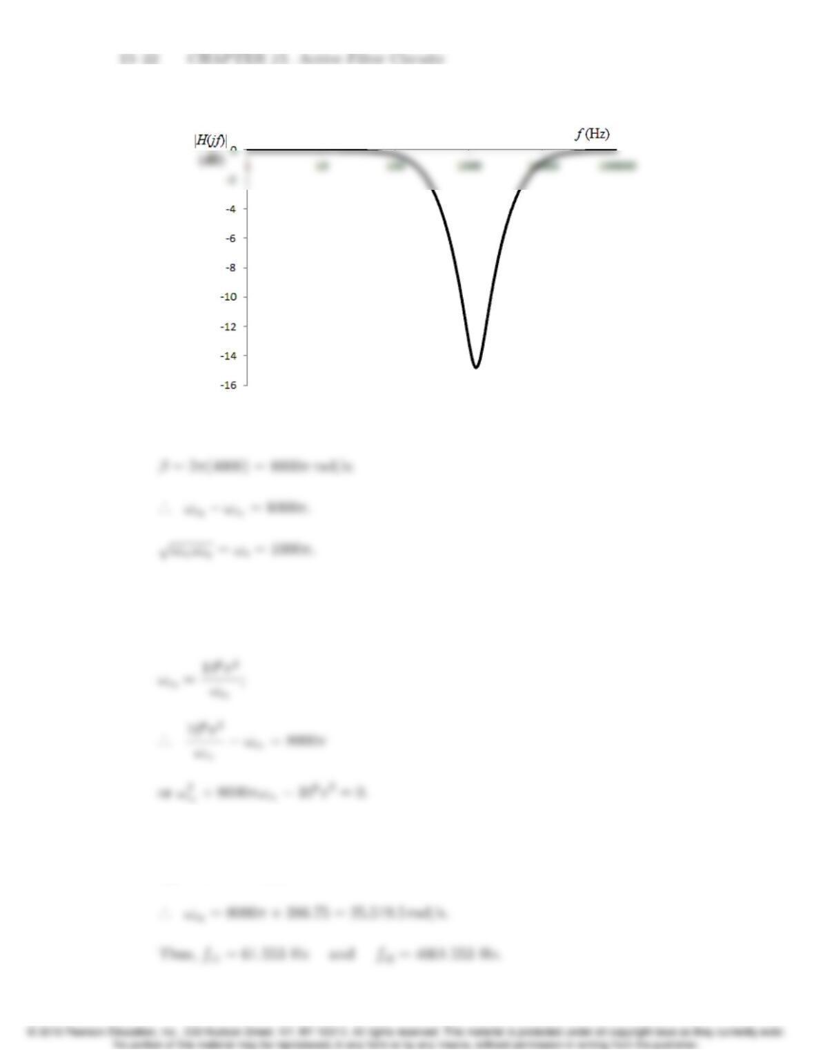
P 15.30 ωo=2πfo= 1000πrad/s;
Solve for the cutofffrequencies:
ωc1ωc2= 106π2;
Solving,
ωc1= 386.75 rad/s;
Problems 15–23
Check: β=fc2fc1= 400 Hz.
P 15.31 ωo= 250 rad/s;
β= 2000 rad/s; C=1µF.
Solve for the cutofffrequencies:
·
.. ω
2
c1+ 2000ωc12502= 0;
ωc1=1
RLCL
;
P 15.32 H(s)=Vo
Vi
=Zf
Zi
;
[a] H(s)= 250s
(s+ 50)(s+ 20) =250s
s2+70s+ 1000 =3.57(70s)
s2+70s+(
p1000)2;
[b] Q=ωo
β=0.45;
P 15.33 [a] H(s)= (1/sC)
R+ (1/sC)=(1/RC)
s+ (1/RC);
Problems 15–25
[b] Let Vabe the voltage across the capacitor, positive at the upper terminal.
Then
VaVin
R1
+sCVa+Va
R2+sL =0.
Solving for Vayields
Therefore
[c] Let Vabe the voltage across R2positive at the upper terminal. Then
VaVin
R1
+Va
R2
+VasC +VasC = 0;
It follows directly that
15–26 CHAPTER 15. Active Filter Circuits
P 15.35 For the scaled circuit
1C0
2
where
It follows that
Problems 15–27
[b] fc= 800 Hz; ωc= 1600πrad/s; kf= 1600π.
[c] H0(j5000π)=0.03275/127.366;
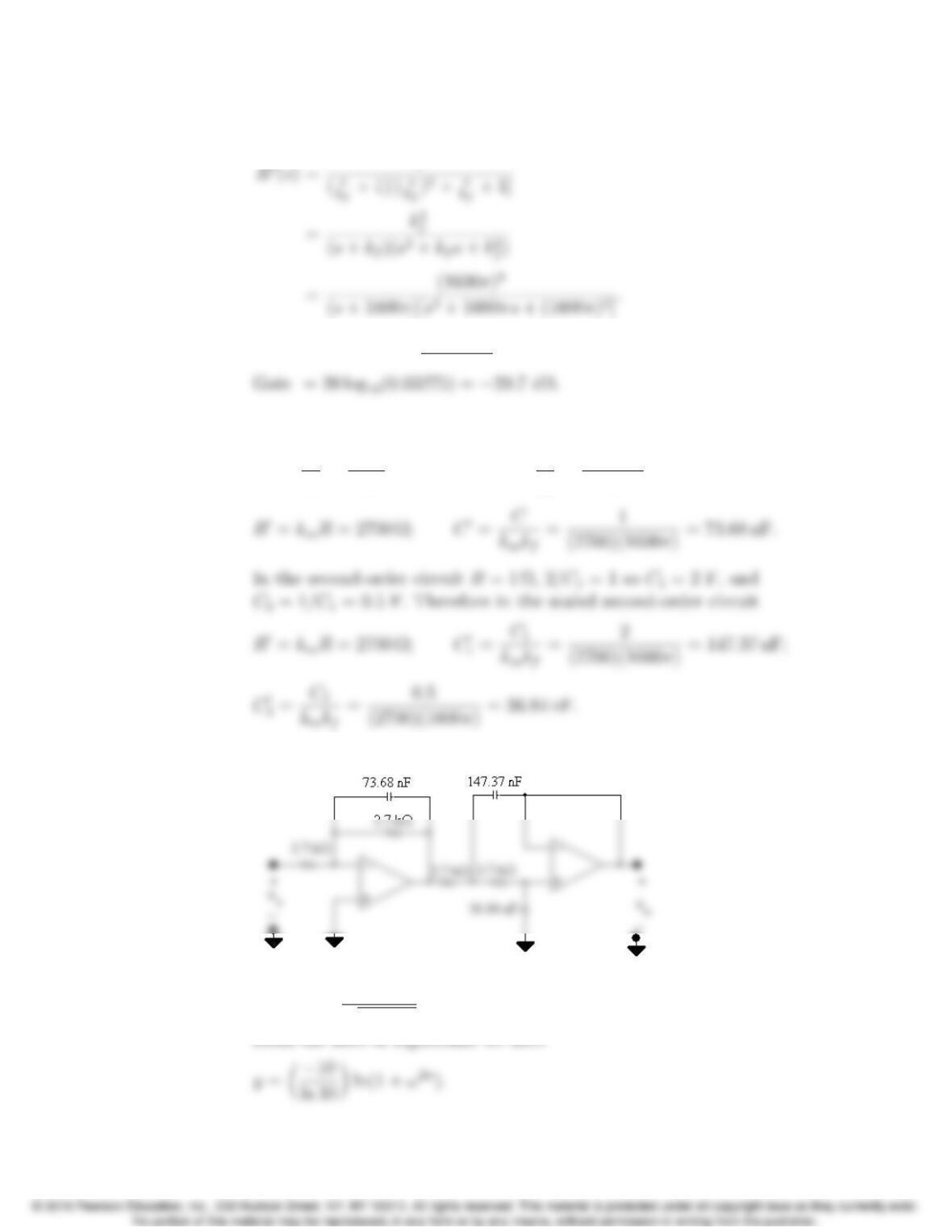
P 15.37 [a] In the first-order circuit R= 1 Ωand C= 1 F.
km=R0
R=2700
1= 2700; kf=ω0
c
ωc
=2π(800)
1= 1600π;
[b]
P 15.38 [a] y= 20 log10
1
p1+ω2n=10 log10(1 + ω2n).
15–28 CHAPTER 15. Active Filter Circuits
Thus
dy
dω=✓10
ln 10◆2nω2n1
(1 + ω2n);
[b] y= 20 log10
1
[p1+ω2]n=10nlog10(1 + ω2)
[c] For the Butterworth Filter For the cascade of identical sections
ndy/dx (dB/decade) n dy/dx (dB/decade)
110 1 10

Problems 15–29
[d] It is apparent from the calculations in part (c) that as nincreases the
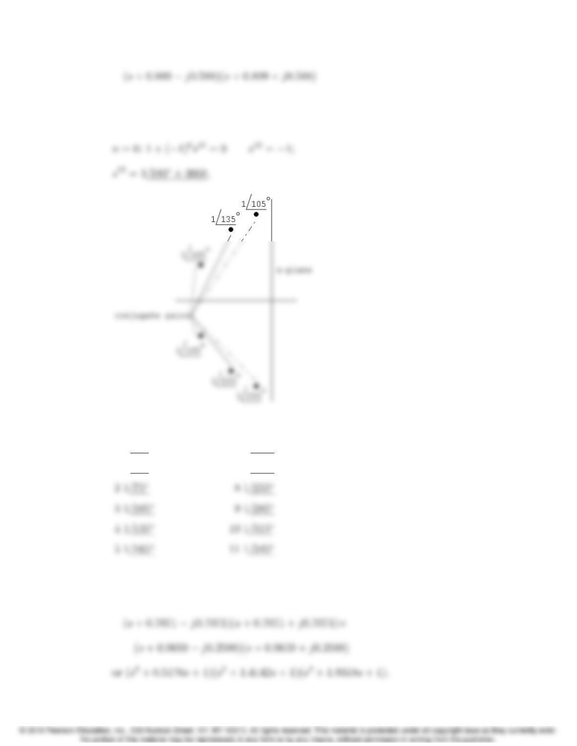
P 15.39 n= 5: 1 + (1)5s10 = 0; s10 = 1;
ks
k+1 ks
k+1
01
/051
/180
Group by conjugate pairs to form denominator polynomial.
(s+ 1)[s(cos 108+jsin 108)][(s(cos 252+jsin 252)]
15–30 CHAPTER 15. Active Filter Circuits
which reduces to
(s+ 1)(s2+0.618s+ 1)(s2+1.618s+1).
ks
k+1 ks
k+1
01
/1561
/195
11
/4571
/225
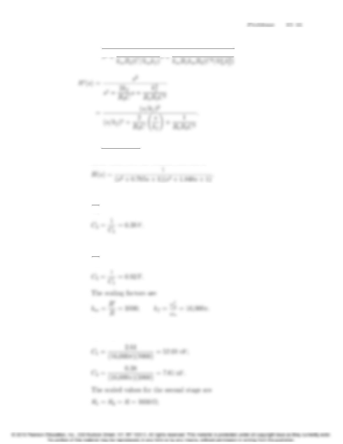
Grouping by conjugate pairs yields
(s+0.2588 j0.9659)(s+0.2588 + j0.9659)⇥
P 15.40 H0(s)= s2
.
P 15.41 [a] n=(0.05)(48)
log10(32/8) =3.99 ·
.. n=4.
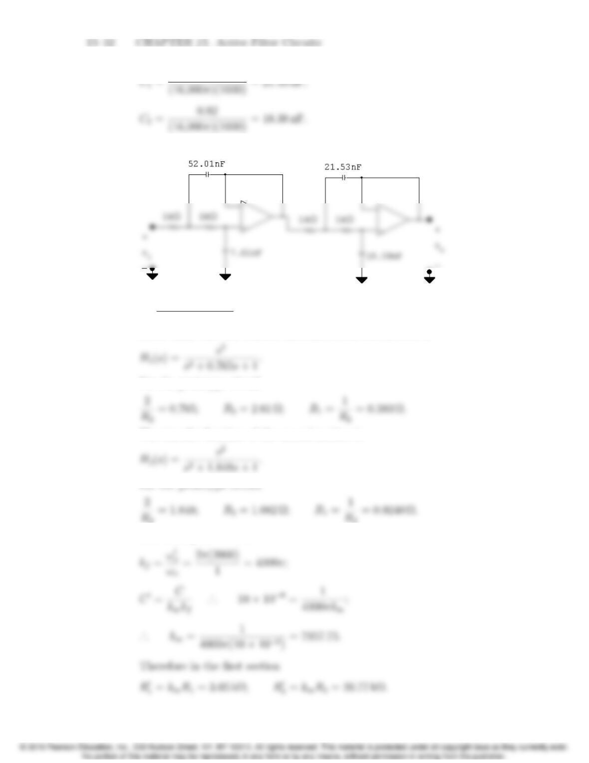
From Table 15.1 the transfer function is
The capacitor values for the first stage prototype circuit are
2
C1
=0.765 ·
.. C
1=2.61 F;
The values for the second stage prototype circuit are
2
C1
=1.848 ·
.. C
1=1.08 F;
Therefore the scaled values for the components in the first stage are
R1=R2=R= 1000 Ω;
[b]
P 15.42 [a] n=(0.05)(48)
log10(2000/500) =3.99 ·
.. n=4.
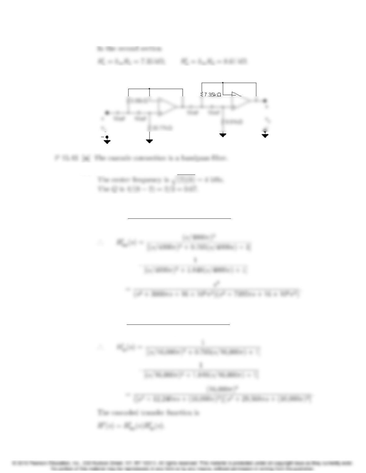
From Table 15.1 the transfer function of the first section is
For the prototype circuit
The transfer function of the second section is
The scaling factors are:
Problems 15–33
[b]
[b] The cutofffrequencies are 2 kHz and 8 kHz.
[c] For the high pass section kf= 4000π. The prototype transfer function is
Hhp(s)= s4
(s2+0.765s+ 1)(s2+1.848s+1);
For the low pass section kf= 16,000π:
Hlp(s)= 1
(s2+0.765s+ 1)(s2+1.848s+1);
15–34 CHAPTER 15. Active Filter Circuits
For convenience let
D1=s2+ 3060πs+16⇥106π2;
[d] ωo=2π(4000) = 8000πrad/s;
s=j8000π;
s2=64 ⇥106π2;
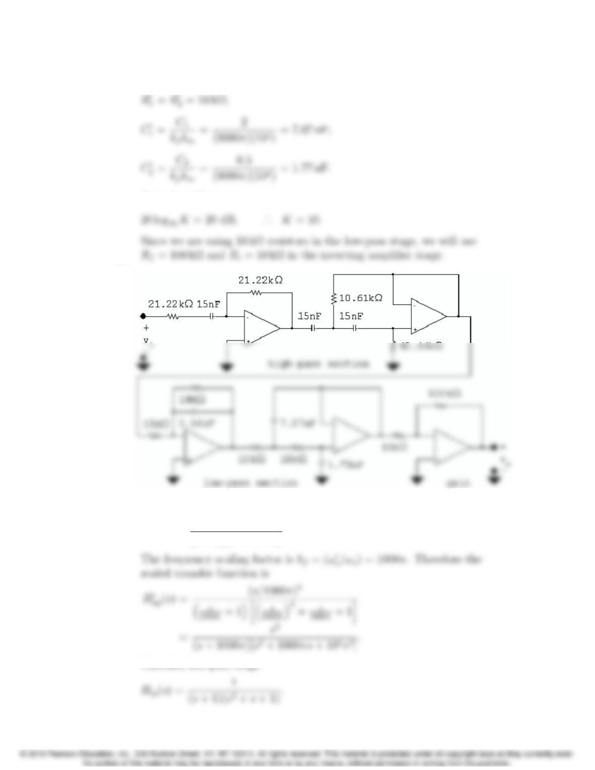
P 15.44 [a] First we will design a unity gain filter and then provide the passband gain
with an inverting amplifier. For the high pass section the cut-off
frequency is 500 Hz. The order of the Butterworth is
(s+ 1)(s2+s+1).
Problems 15–35
For the prototype first-order section
For the prototype second-order section
The scaling factors are
kf=ω0
o
ωo
=2π(500) = 1000π;
In the scaled first-order section
In the scaled second-order section
For the low-pass section the cut-offfrequency is 4500 Hz. The order of
the Butterworth filter is
For the prototype first-order section
The low-pass scaling factors are
15–36 CHAPTER 15. Active Filter Circuits
For the scaled second-order section
Gain Amplifier:
[b]
P 15.45 [a] Unscaled high-pass stage
Hhp(s)= s3
(s+ 1)(s2+s+1).
Problems 15–37
The frequency scaling factor is kf=(ω0
o/ωo) = 9000π. Therefore the
[b] At 200 Hz ω= 400πrad/s:
D1(j400π) = 400π(2.5+j1);
Therefore
Then
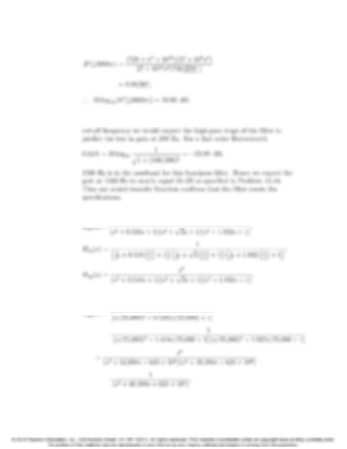
15–38 CHAPTER 15. Active Filter Circuits
D4(j3000π)=10
6π2(8 + j3.
[c] From the transfer function the gain is down 19.99 + 3.89 or 23.88 dB at
200 Hz. Because the upper cut-offfrequency is nine times the lower
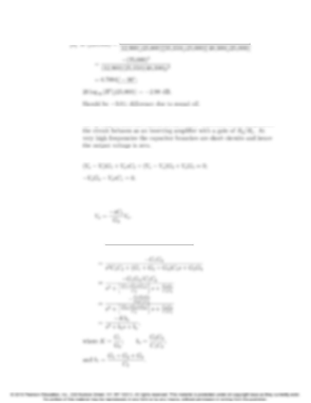
P 15.46 [a] From Table 15.1
P 15.47 [a] kf= 25,000;
H0
Problems 15–39
P 15.48 [a] At very low frequencies the two capacitor branches are open and because
the op amp is ideal the current in R3is zero. Therefore at low frequencies
[b] Let the node where R1,R2,R3, and C2join be denoted as a, then
or
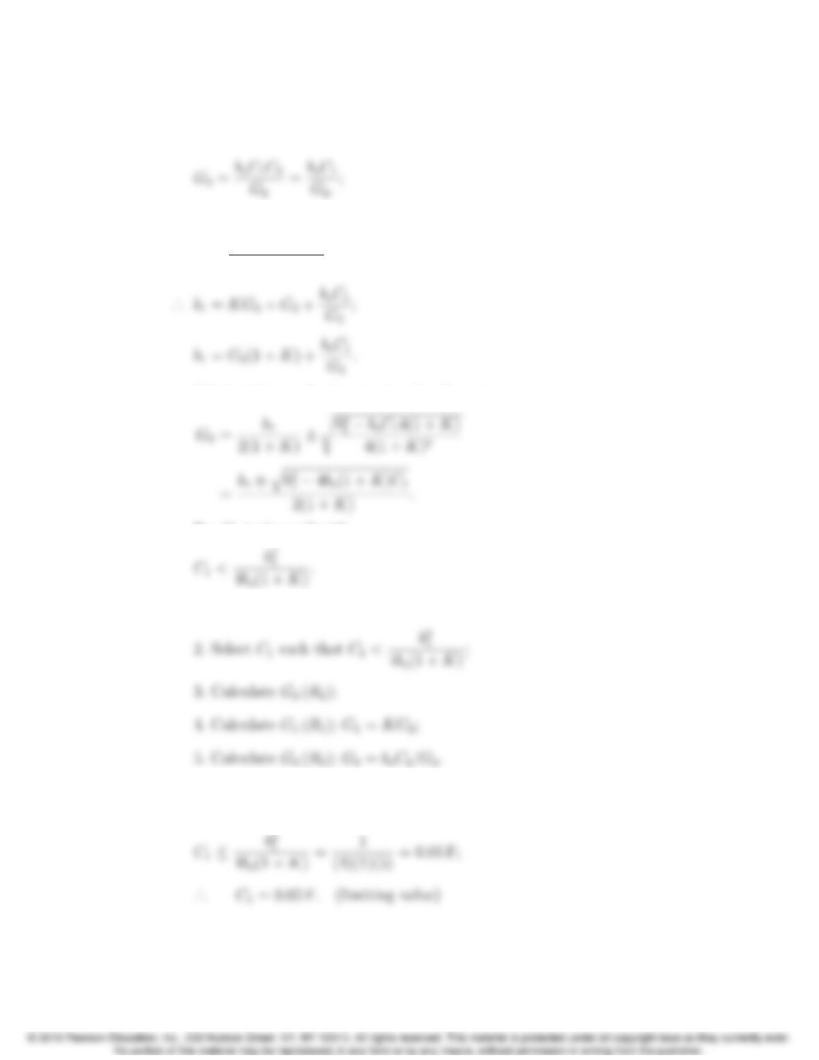
(G1+G2+G3+sC2)VaG2Vo=G1Vi;
Solving for Vo/Viyields
H(s)= G1G3
(G1+G2+G3+sC2)sC1+G2G3
15–40 CHAPTER 15. Active Filter Circuits
[c] Rearranging we see that
G1=KG2;
Since by hypothesis C2=1F
b1=G1+G2+G3
C2
=G1+G2+G3;
Solving this quadratic equation for G2we get
For G2to be realizable
[d] 1. Select C2= 1 F;
P 15.49 [a] In the second order section of a third order Butterworth filter bo=b1=1
Therefore,