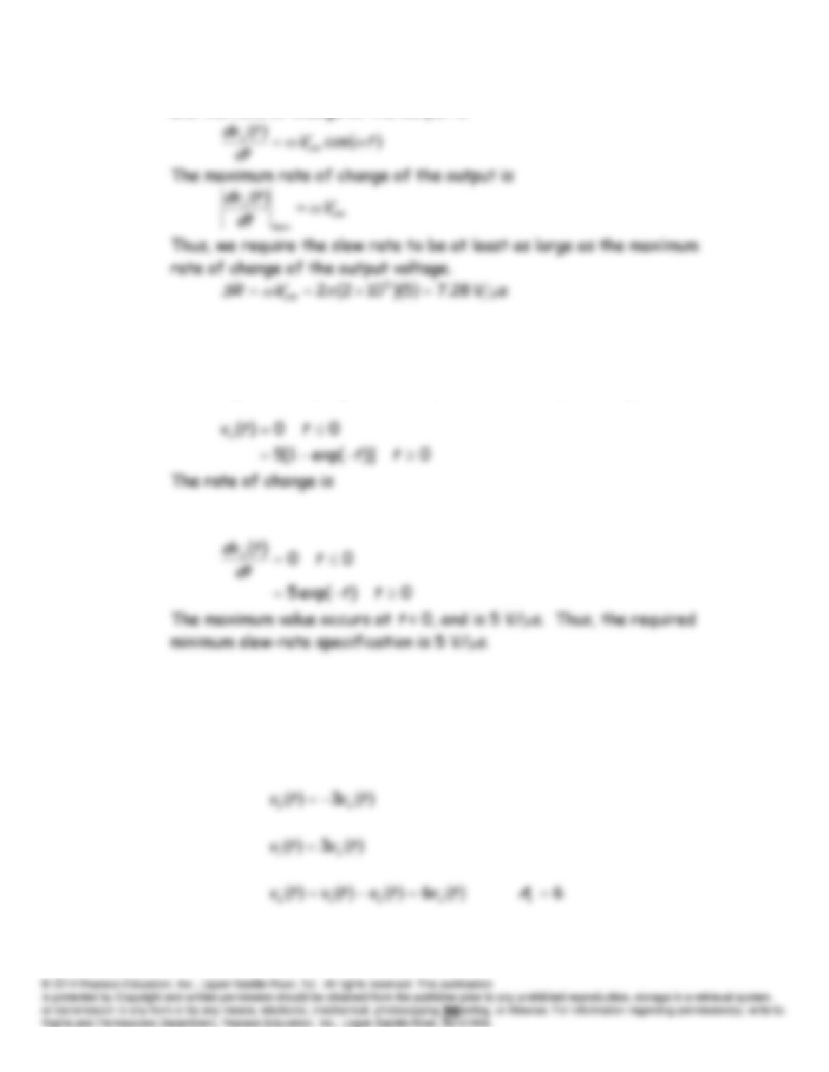
and the rate of change of the output is
P14.60 To avoid slew-rate distortion, the op-amp slew-rate specification must
exceed the maximum rate of change of the output-voltage magnitude.
For the gain and input given in the problem, the output voltage is
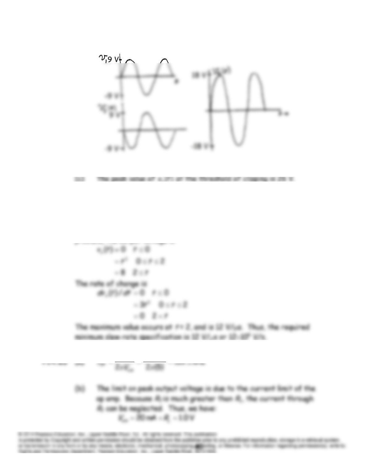
P14.61 (a) One op amp (the lower one in the Figure) is configured as an
inverting amplifier with a gain of -3 and the other op amp (the top one in
the figure) is configured as a noninverting amplifier with
a gain +3. Thus, we can write:
(b)
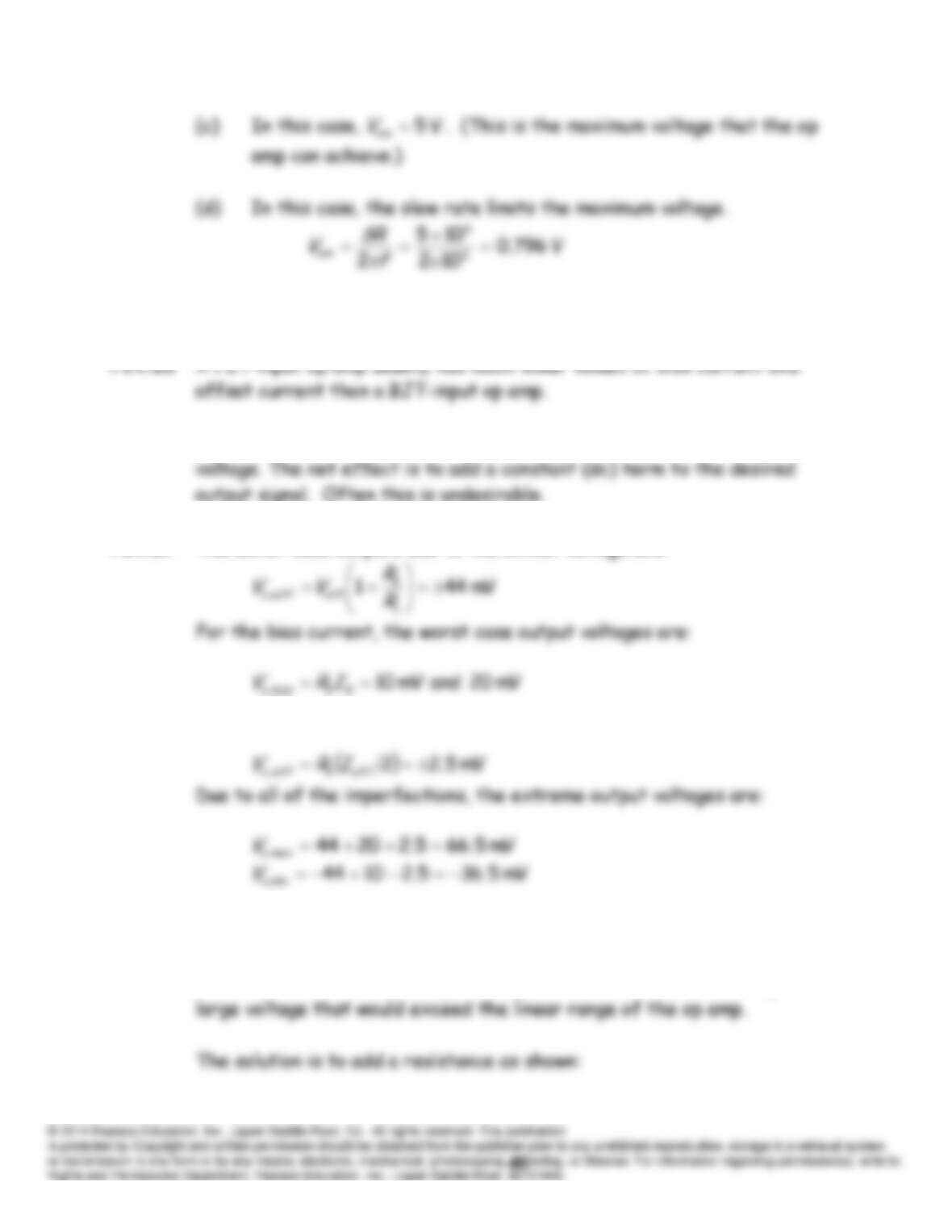
P14.62 To avoid slew-rate distortion, the op-amp slew-rate specification must
exceed the maximum rate of change of the output-voltage magnitude.
For a voltage follower, the gain is unity. For the input given in the
problem, the output voltage is
105
6
SR
P14.64* See Figure 14.29 in the text.
P14.66 The dc imperfections are bias current, offset current, and offset
P14.67* The worst-case outputs due to the offset voltage are:
For the offset current, the worst-case output voltages are:
P14.68 The circuit shown in Figure P14.67 is a poor design because no dc path is
provided for the bias current flowing into the noninverting input terminal.
The bias current would charge the capacitance eventually resulting in a
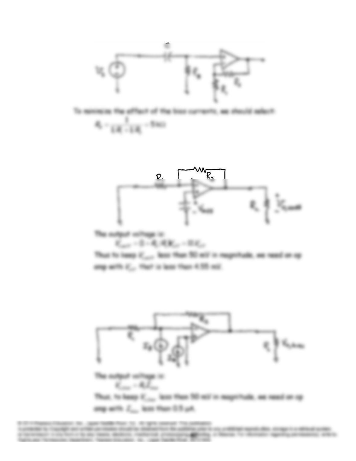
P14.69 (a) The circuit with the signal source zeroed and including the offset
voltage source is:
(b) The circuit with only the bias current sources is:
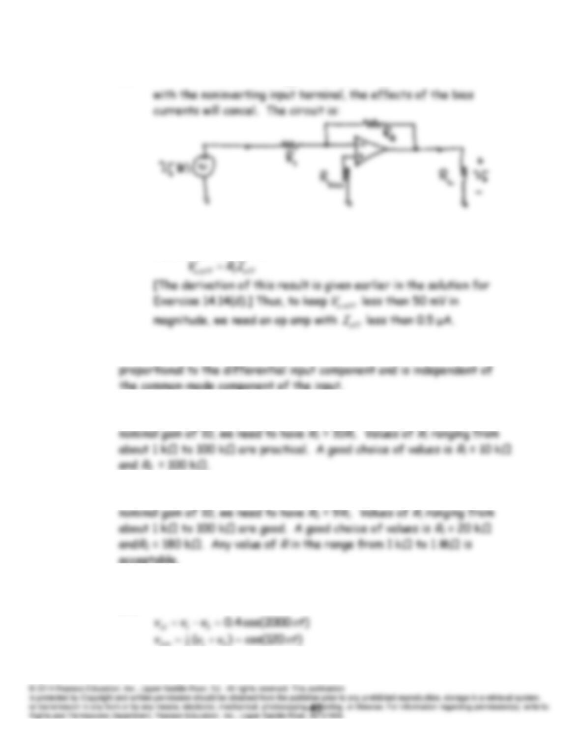
(c) If we add a resistance
k 09.9)/1/1/(121
bias
RRR
in series
(d) With the resistance of part (c) in place, the output voltage due to
the offset current is:
P14.70 The function of a differential amplifier is to produce an output that is
P14.71* The circuit diagram is shown in Figure 14.33 in the text. To achieve a
P14.72 The circuit diagram is shown in Figure 14.34 in the text. To achieve a
P14.73 (a) The differential and common-mode components of the input signal
are:
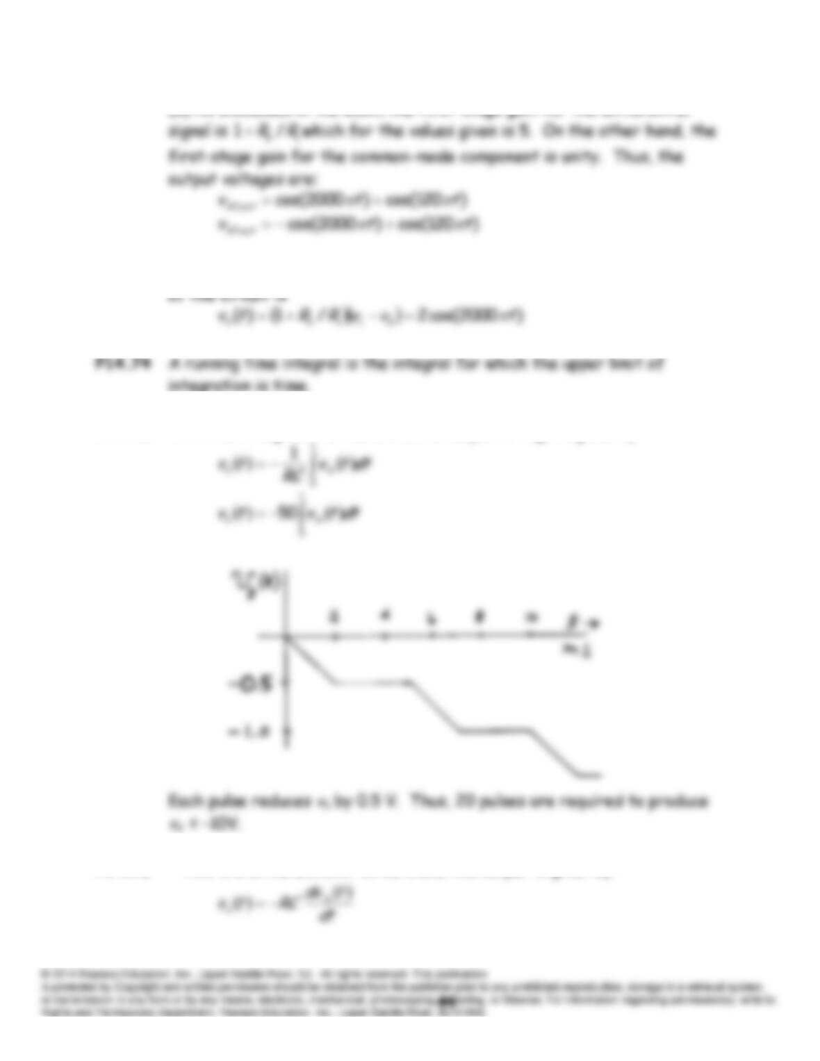
(b) As discussed in the book, the first-stage gain for the differential
(c) Assuming ideal op amps and perfectly matched components, the output
P14.75* This is an integrator circuit, and the output voltage is given by:
P14.76 This is a differentiator circuit, and the output is given by:
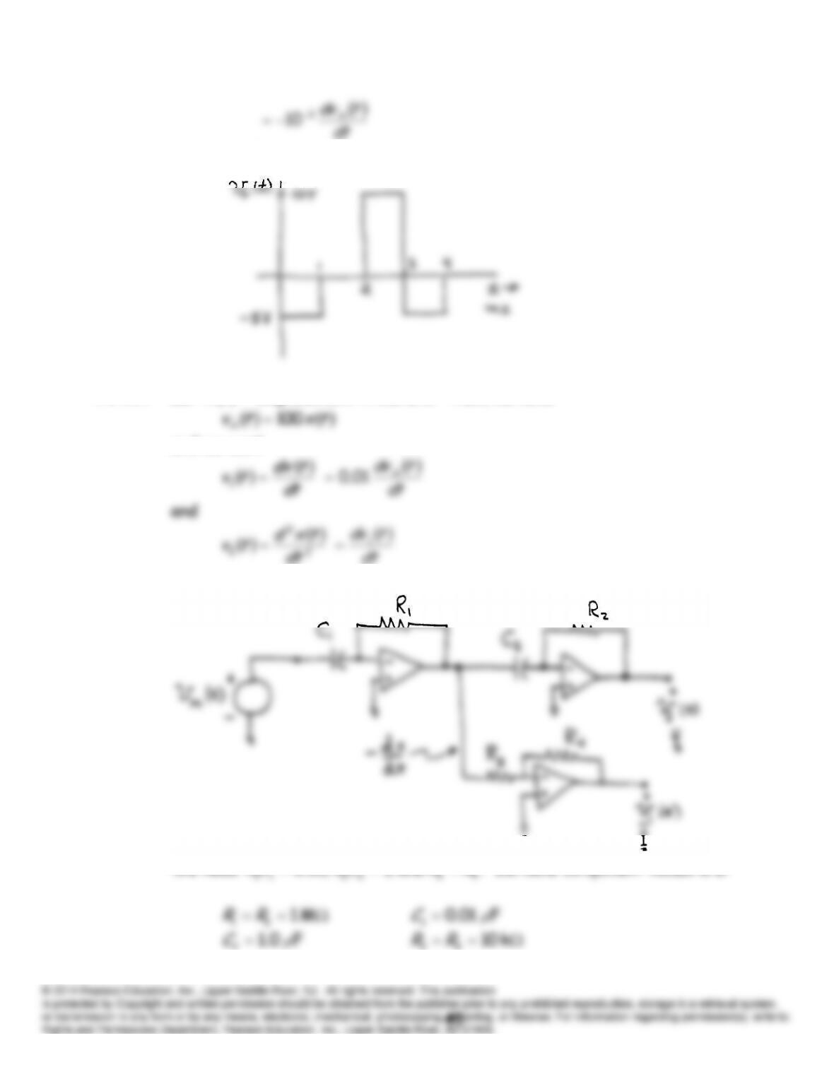
A sketch of
tvo
versus is:
P14.77 Let
tx
displacement in meters. Then, we have
and we want
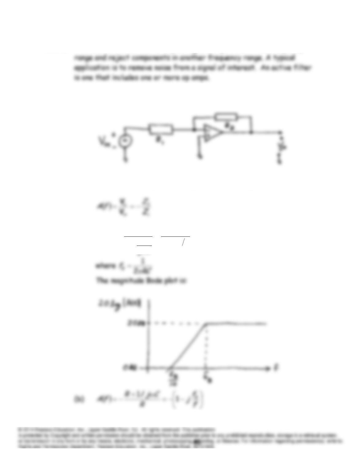
A circuit that produces the desired voltages is:
We need
RRCRCR
. Suitable component values are:
2μ
43
P14.78 The function of a filter is to pass signal components in one frequency
P14.79* Both of the circuits are of the form:
This is the inverting amplifier configuration and the gain is
(a)
fjf
Cj
R
R
fA
B
1
10
1
10
ω
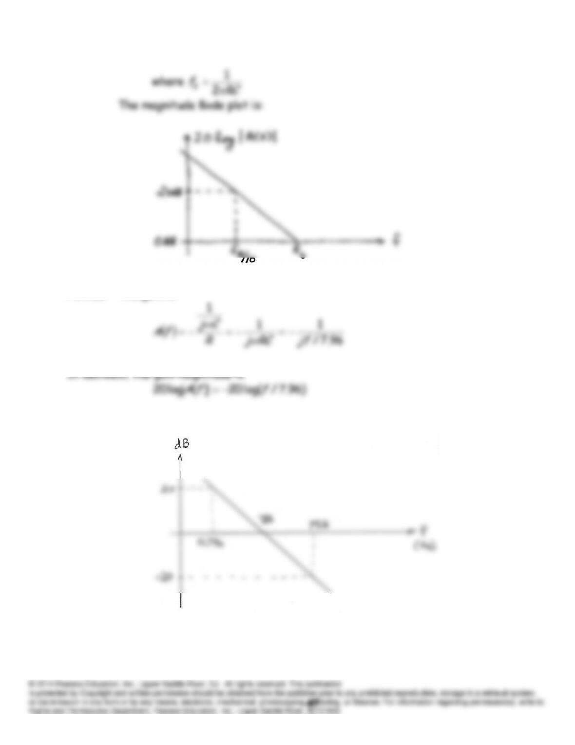
P14.80 The gain is:
The sketch is:
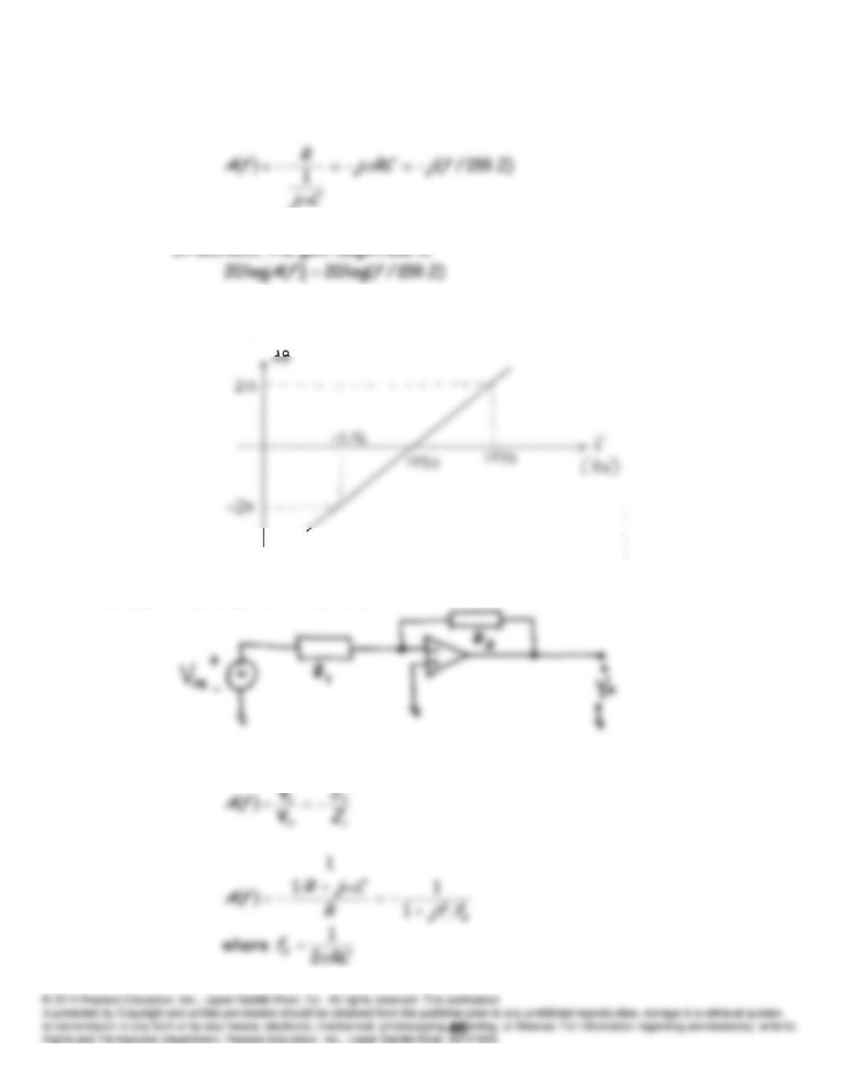
P14.81 The gain is:
The sketch is:
P14.82 The circuit is of the form
This is the inverting amplifier configuration and the gain is
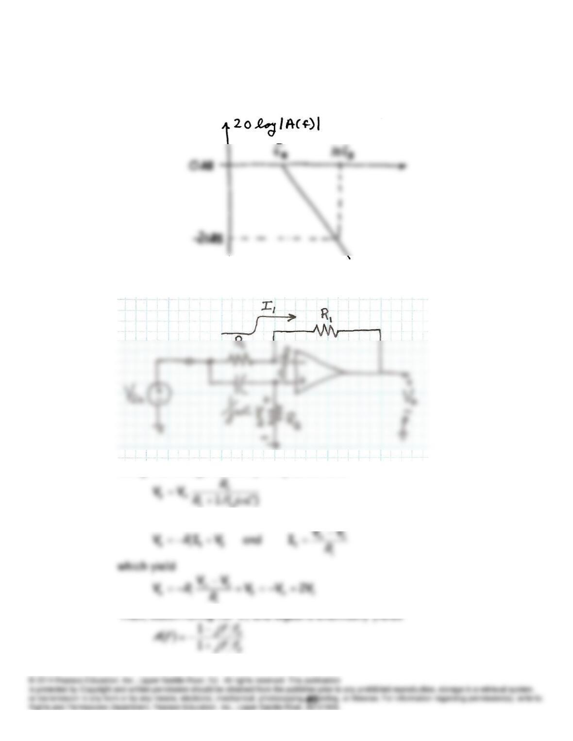
The magnitude Bode plot is:
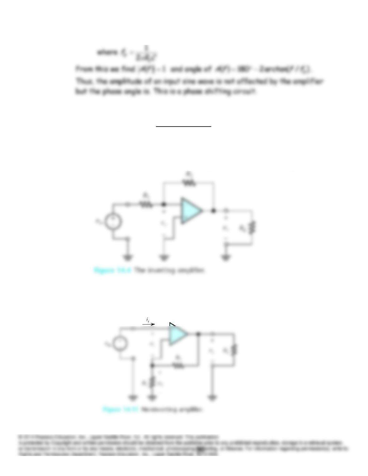
P14.83 The circuit is
Using the voltage division principle, we have
Also, we have
1
Practice Test
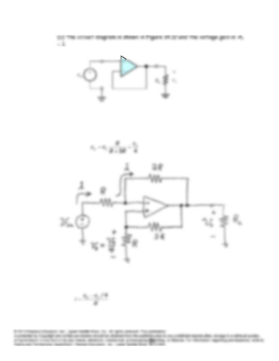
T14.1 (a) The circuit diagram is shown in Figure 14.4 and the voltage gain is
Av
R
2/
R
1. Of course, you could use different resistance labels such as
RA
and
RB
so long as your equation for the gain is modified accordingly.
(b) The circuit diagram is shown in Figure 14.11 and the voltage gain is
Av
1
R
2/
R
1.
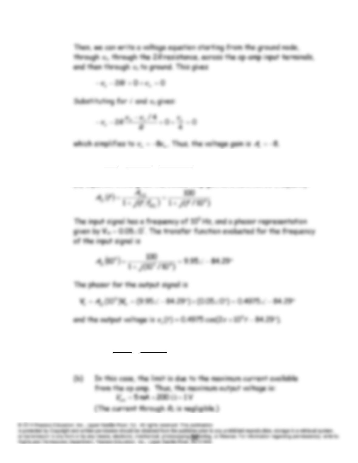
T14.2 Because the currents flowing into the op-amp input terminals are zero,
we can apply the voltage-division principle to determine the voltage
vx
at
the noninverting input with respect to ground:
This is also the voltage at the inverting input, because the voltage
between the op-amp input terminals is zero. Thus, the current
i
is
T14.3 (a)
kHz 10
100
51025
0
0
0
CL
BOLOL
CL
t
BCL A
fA
A
f
f
(b) Equation 14.32 gives the closed-loop gain as a function of frequency:
T14.4 (a)
kHz 4.707
5.42
1020
2
6
om
FP V
SR
f
(d) In this case, the slew-rate is the limitation.
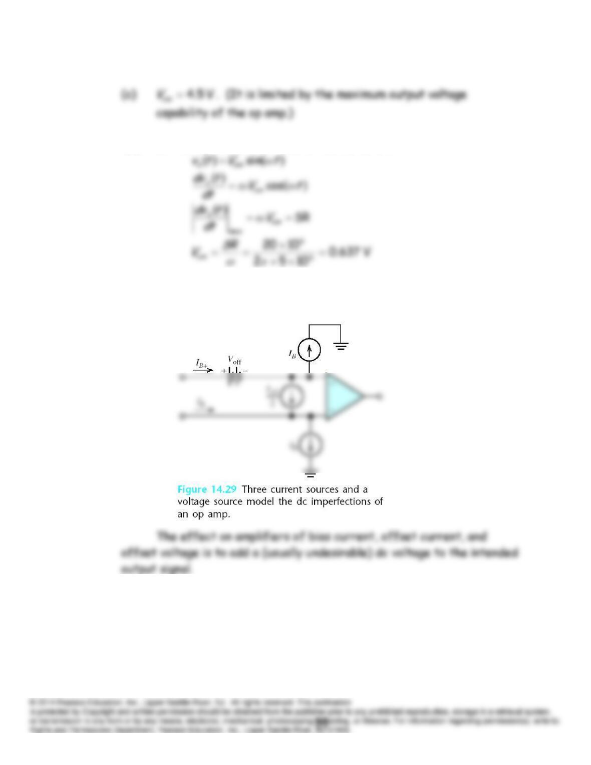
T14.5 See Figure 14.29 for the circuit.
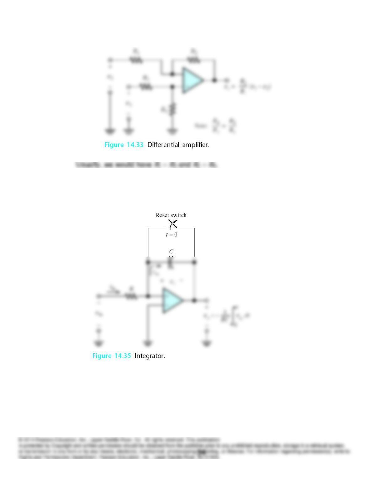
T14.6 See Figure 14.33 in the book.
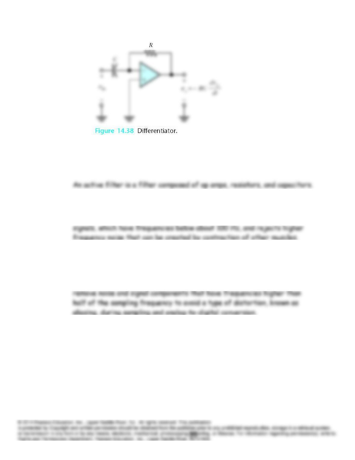
T14.7 See Figures 14.35 and 14.38 in the book:
T14.8 Filters are circuits designed to pass input components with frequencies in
one range to the output and prevent input components with frequencies in
other ranges from reaching the output.
Some applications for filters mentioned in the text are:
1. In an electrocardiograph, we need a filter that passes the heart
2. Using a lowpass filter to remove noise from historical phonograph
recordings.
3. In digital instrumentation systems, a low pass filter is often needed to