14–18 CHAPTER 14. Introduction to Frequency-Selective Circuits
Then, R=ωoL
Q=(46,126.56)(0.01)
2= 230 Ω.
2(100) = 5%.
P 14.30 [a] ω2
o=1
LC =1
(10 ⇥103)(10 ⇥109)= 1010;
P 14.31 [a] ω2
o=1
LC =1
(5 ⇥103)(200 ⇥1012)= 1012;
Problems 14–19
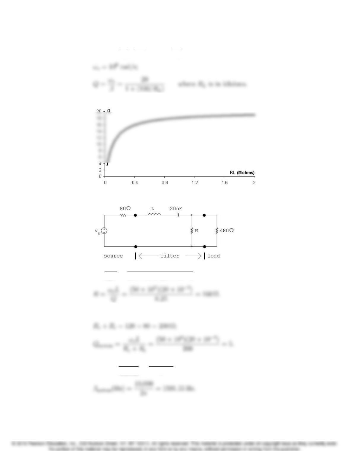
[e] β=✓1+ R
RL◆1
RC =✓1+100
RL◆(50 ⇥103) rad/s
[f]
P 14.32 [a]
[b] L=1
ω2
oC=1
(50 ⇥103)2(20 ⇥104)= 20 mH;
[c] Re= 160k480 = 120 Ω;
[d] βsystem =ωo
Qsystem
=50 ⇥103
5= 10 krad/s;
P 14.33 [a] Vo
Vi
=Z
Z+Rwhere Z=1
Y
and Y=sC +1
sL +1
RL
=LCRLs2+sL +RL
RLLs .
[c] βU=1
RC ;
[e] QU=ωoRC;
[f] H(jω)= Kjωβ
ω2
oω2+jωβ;
Let ωcrepresent a corner frequency. Then
Squaring both sides leads to
Problems 14–21
·
.. ω
2
c±ωcβω2
o=0
P 14.34 ω2
o=1
LC =1
(2 ⇥106)(50 ⇥1012)= 1016;
P 14.35 H(s)= s2+1
LC
s2+R
Ls+1
LC
.
14–22 CHAPTER 14. Introduction to Frequency-Selective Circuits
P 14.36 [a] H(jω)=
1
LC ω2
1
LC ω2+jR
Lω
=10002ω2
10002ω2+j500ω.
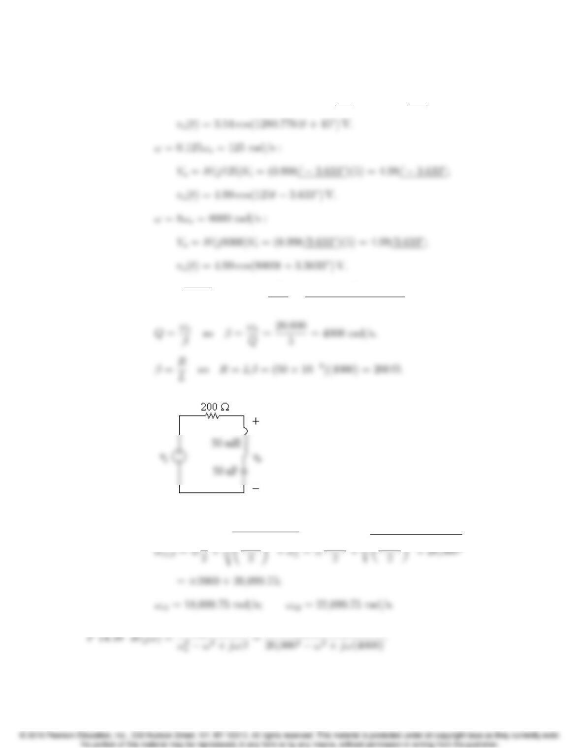
ωo= 1000 rad/s :
0.125ωo= 125 rad/s :
[b] ω=ωo= 1000 rad/s : Vo=H(j1000)Vi=0Vi;
vo(t)=0.
Problems 14–23
ω=ωc2= 1280.7764 rad/s :
Vo=H(j1280.7764)Vi= (0.7071/45)(5) = 3.54/45;
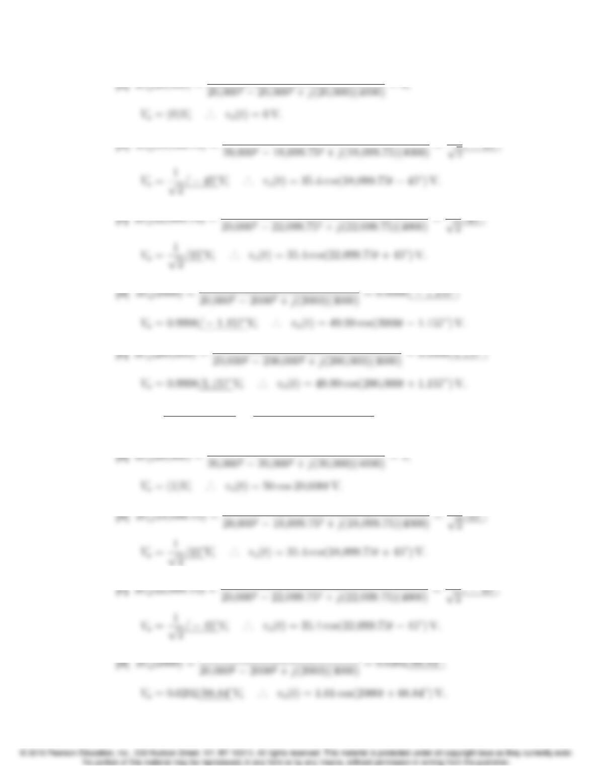
P 14.37 [a] ωo=q1/LC so L=1
ω2
oC=1
(20,000)2(50 ⇥109)= 50 mH.
[b] From part (a), β= 4000 rad/s.
u
u
t beta
oω2
14–24 CHAPTER 14. Introduction to Frequency-Selective Circuits
P 14.39 H(jω)= jωβ
ω2
oω2+jωβ =jω(4000)
20,0002ω2+jω(4000).
Problems 14–25
P 14.40 [a] In analyzing the circuit qualitatively we visualize vias a sinusoidal voltage
and we seek the steady-state nature of the output voltage vo.
At zero frequency the inductor provides a direct connection between the
[b] Let Zrepresent the impedance of the parallel branches Land C, thus
Z=sL(1/sC)
sL +1/sC =sL
s2LC +1.
Then
[c] From part (b) we have
[d] |H(jω)|=ω2
oω2
q(ω2
oω2)2+ω2β2;
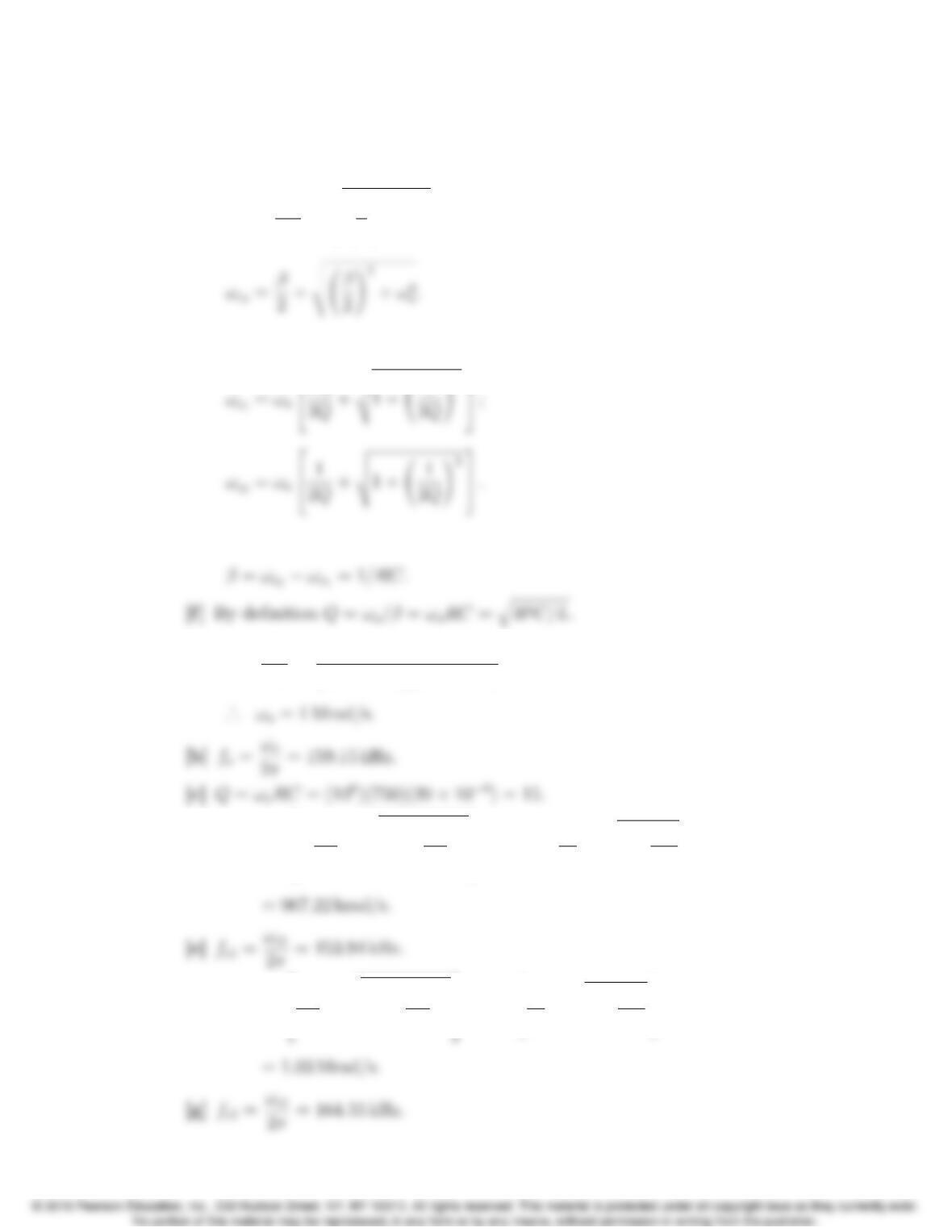
14–26 CHAPTER 14. Introduction to Frequency-Selective Circuits
ω2±βω ω2
o=0.
The two positive roots of this quadratic are
ωc1=β
2+v
u
u
t β
2!2
+ω2
o;
Also note that since β=ωo/Q
u
u
[e] It follows from the equations derived in part (d) that
P 14.41 [a] ω2
o=1
LC =1
(50 ⇥106)(20 ⇥109)= 1012;
[d] ωc1=ωo2
6
41
2Q+v
u
u
t1+ 1
2Q!23
7
5= 1062
41
30 +s1+ 1
900 3
5
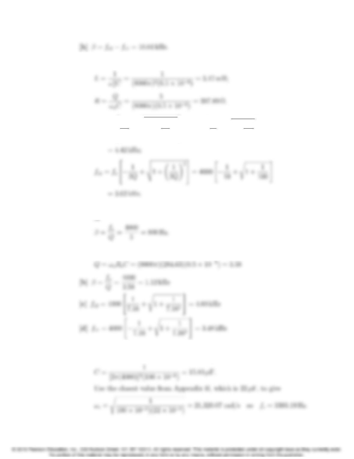
[f] ωc2=ωo2
6
4
1
2Q+v
u
u
t1+ 1
2Q!23
7
5= 1062
4
1
30 +s1+ 1
900 3
5
Problems 14–27
P 14.42 [a] ωo=2πfo=8πkrad/s;
[b] fc2=fo2
6
4
1
2Q+v
u
u
t1+ 1
2Q!23
7
5= 4000 2
4
1
10 +s1+ 1
100 3
5
[c] β=fc2fc1= 800 Hz
P 14.43 [a] Re= 397.89k1000 = 284.63 Ω
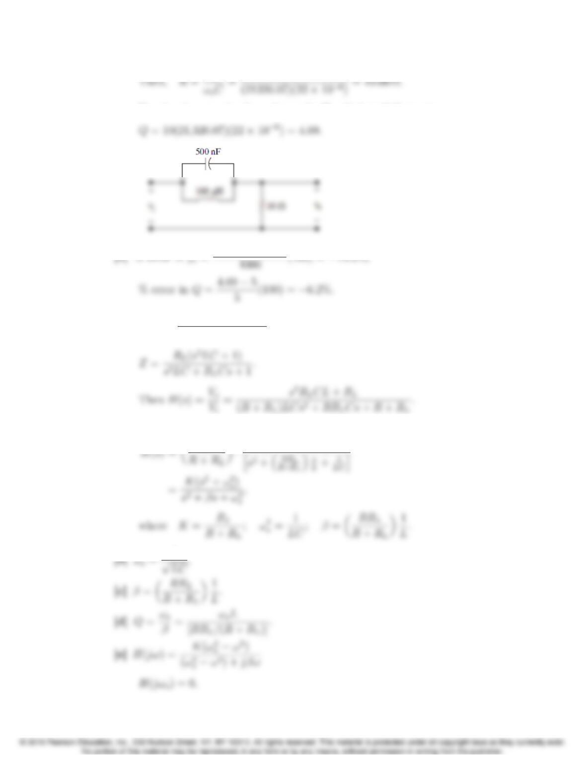
P 14.44 [a] We need ωc=2π(4000) = 25,132.74 rad/s. There are several possible
approaches – this one starts by choosing L= 100 µH. Then,
14–28 CHAPTER 14. Introduction to Frequency-Selective Circuits
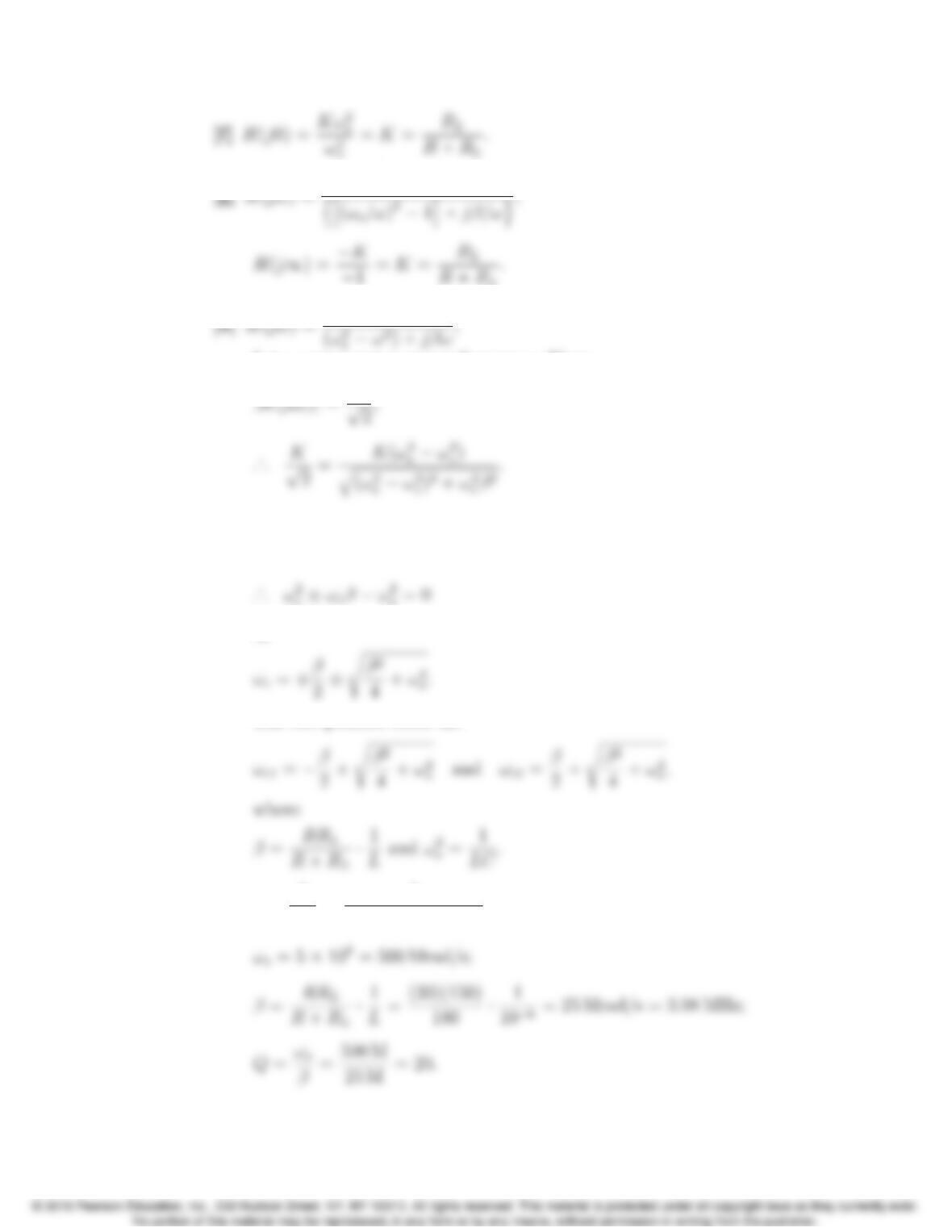
Use the closest value from Appendix H, which is 10 Ω, to give
P 14.45 [a] Let Z=RL(sL + (1/sC))
RL+sL + (1/sC);
Therefore
Problems 14–29
oω2)
Let ωcrepresent a corner frequency. Then
Squaring both sides leads to
(ω2
oω2
c)2=ω2
cβ2or (ω2
oω2
c)=±ωcβ;
or
The two positive roots are
P 14.46 [a] ω2
o=1
LC =1
(106)(4 ⇥1012)=0.25 ⇥1018 = 25 ⇥1016;
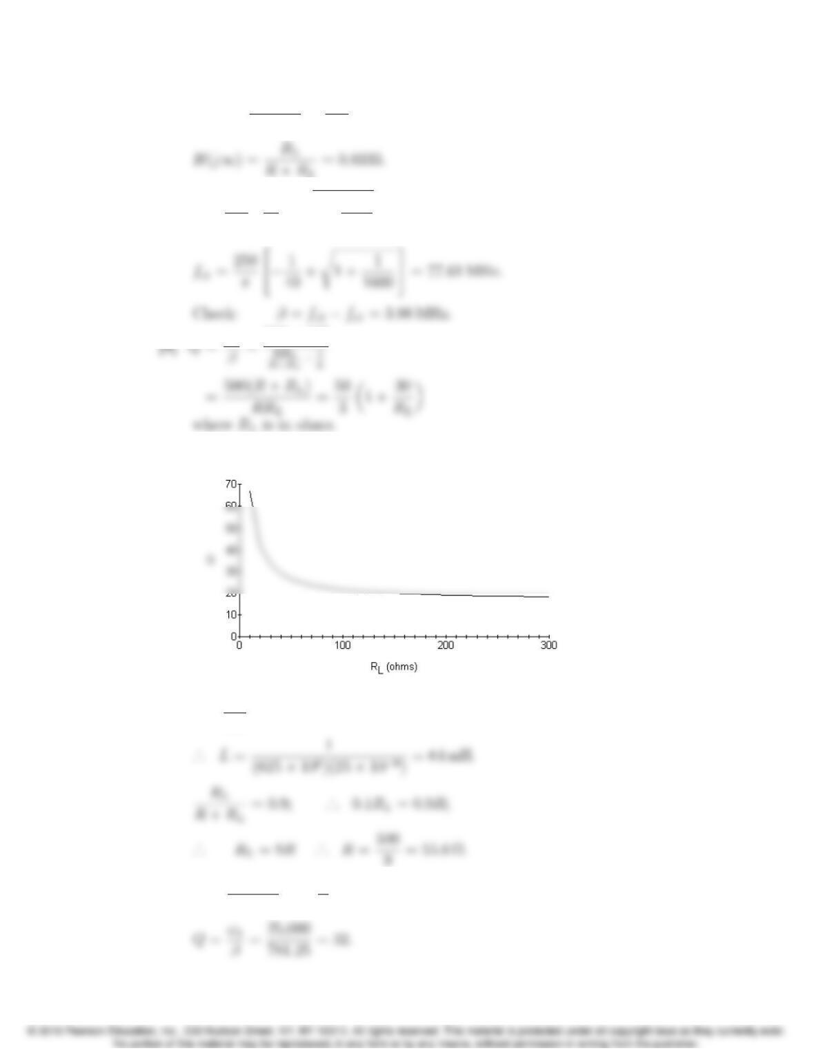
14–30 CHAPTER 14. Introduction to Frequency-Selective Circuits
[b] H(j0) = RL
R+RL
=150
180 =0.8333;
[c] fc2=250
π2
4
1
40 +s1+ 1
1600 3
5= 81.59 MHz;
[e]
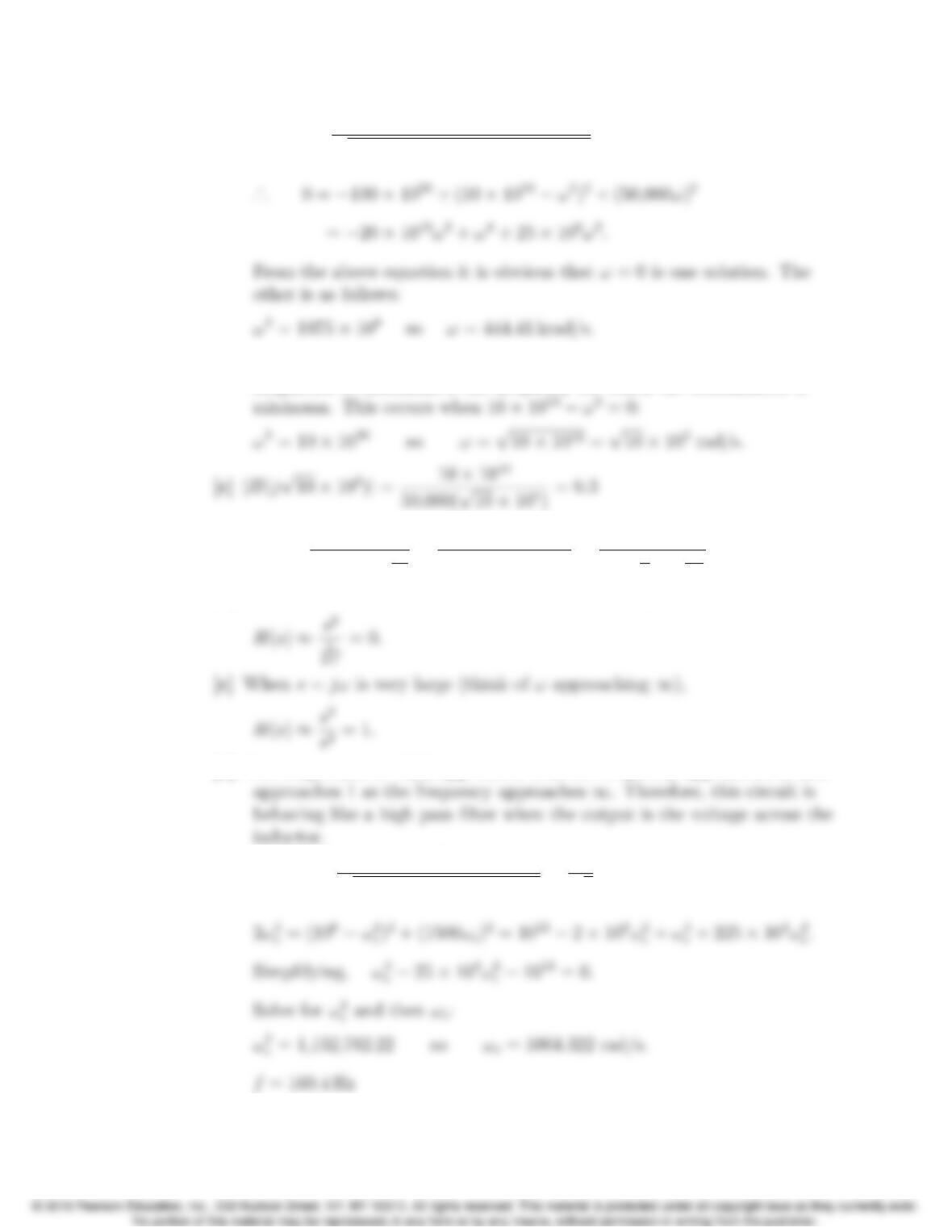
P 14.47 [a] ω2
o=1
LC = 625 ⇥106;
[b] β=✓RL
R+RL◆R·1
L= 781.25 rad/s;
Problems 14–31
P 14.48 [a] |H(jω)|=10 ⇥1010
q(10 ⇥1010 ω2)2+ (50,000ω)2= 1;
[b] From the equation for |H(jω)|in part (a), the frequency for which the
magnitude is maximum is the frequency for which the denominator is
P 14.49 [a] H(s)= sL
R+sL +1
sC
=s2LC
RsC +s2LC +1 =s2
s2+R
Ls+1
LC
.
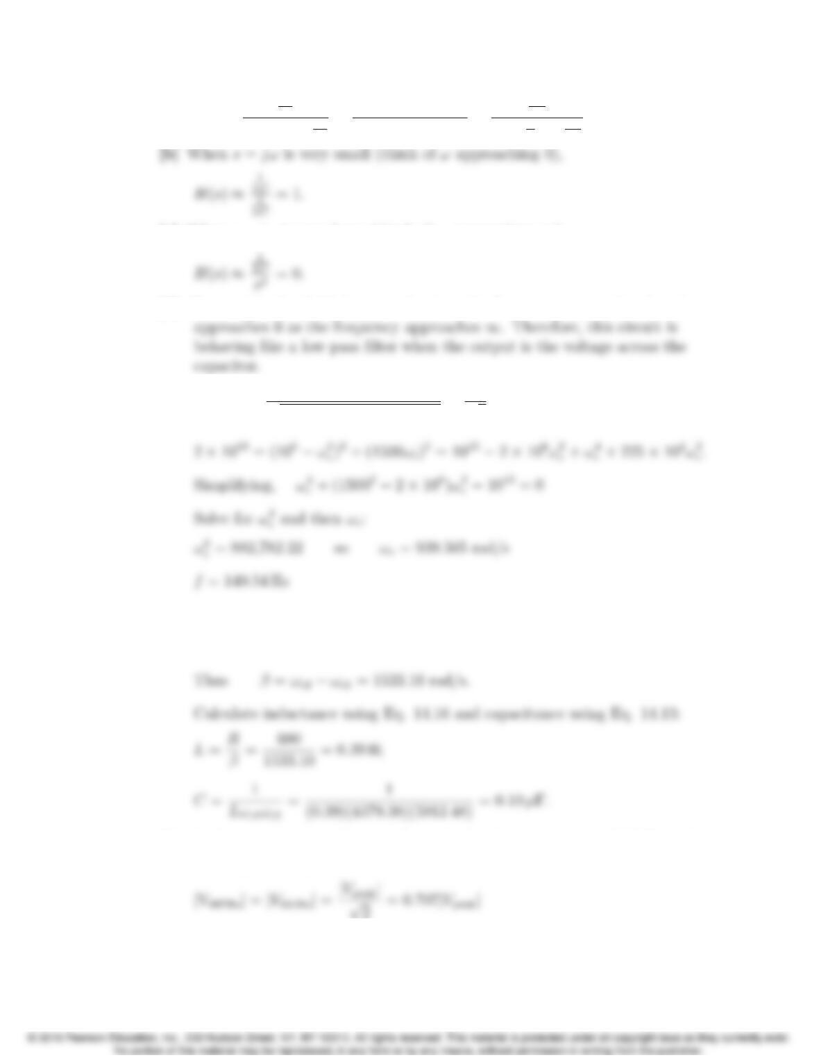
[b] When s=jωis very small (think of ωapproaching 0),
[d] The magnitude of H(s) approaches 0 as the frequency approaches 0, and
[e] |H(jωc)|=ω2
c
q(106ω2
c)2+ (1500ωc)2=1
p2;
14–32 CHAPTER 14. Introduction to Frequency-Selective Circuits
P 14.50 [a] H(s)=
1
sC
R+sL +1
sC
=1
RsC +s2LC +1 =
1
LC
s2+R
Ls+1
LC
.
[c] When s=jωis very large (think of ωapproaching 1),
[d] The magnitude of H(s) approaches 1 as the frequency approaches 0, and
[e] |H(jωc)|=106
q(106ω2
c)2+ (1500ωc)2=1
p2;
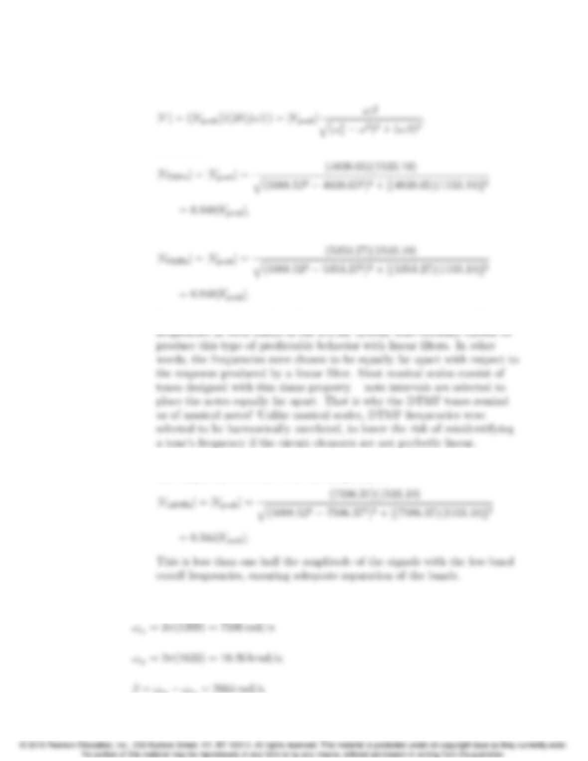
P 14.51 [a] Use the cutofffrequencies to calculate the bandwidth:
ωc1=2π(697) = 4379.38 rad/s ωc2=2π(941) = 5912.48 rad/s;
[b] At the outermost two frequencies in the low-frequency group (687 Hz and
941 Hz) the amplitudes are
Problems 14–33
because these are cutofffrequencies. We calculate the amplitudes at the
other two low frequencies:
Therefore
and
It is not a coincidence that these two magnitudes are the same. The
[c] The high-band frequency closest to the low-frequency band is 1209 Hz.
The amplitude of a tone with this frequency is
P 14.52 The cutofffrequencies and bandwidth are
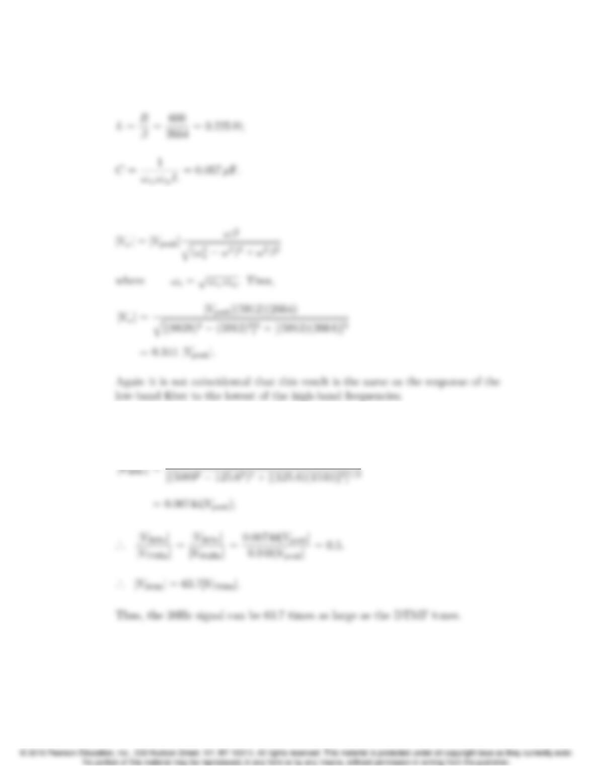
14–34 CHAPTER 14. Introduction to Frequency-Selective Circuits
Telephone circuits always have R= 600 Ω. Therefore, the filters inductance
and capacitance values are
At the highest of the low-band frequencies, 941 Hz, the amplitude is
P 14.53 From Problem 14.51 the response to the largest of the DTMF low-band tones
is 0.948|Vpeak|. The response to the 20 Hz tone is