Problems 13–41
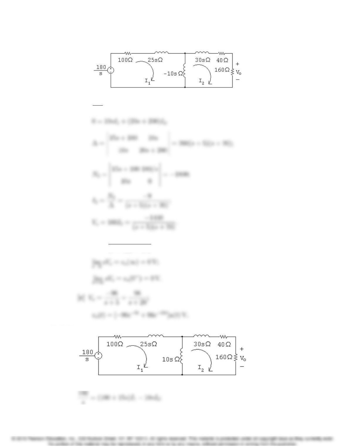
P 13.38 [a]
180
s= (100 + 15s)I1+10sI2;
[b] sVo=1440s
(s+ 5)(s+ 20).
P 13.39
13–42 CHAPTER 13. The Laplace Transform in Circuit Analysis
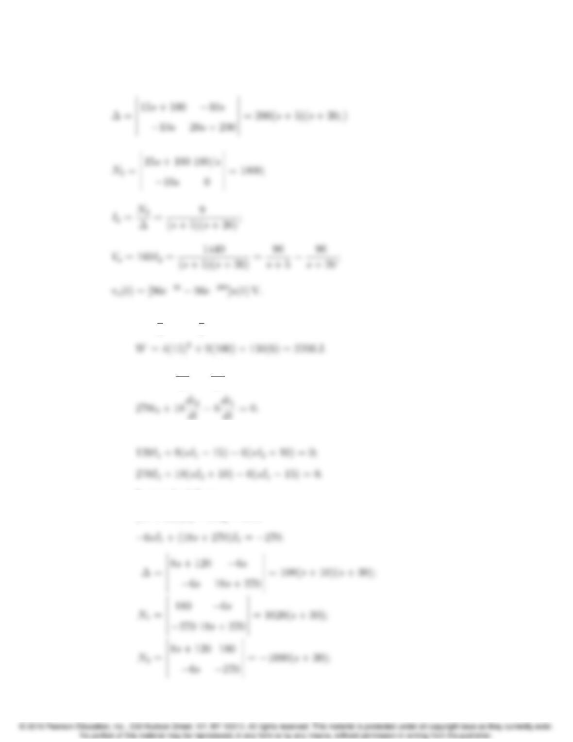
0=10sI1+ (20s+ 200)I2.
P 13.40 [a] W=1
2L1i2
1+1
2L2i2
2+Mi1i2;
[b] 120i1+8di1
dt 6di2
dt = 0;
LaPlace transform the equations to get
In standard form,
(8s+ 120)I16sI2= 180;
Problems 13–43
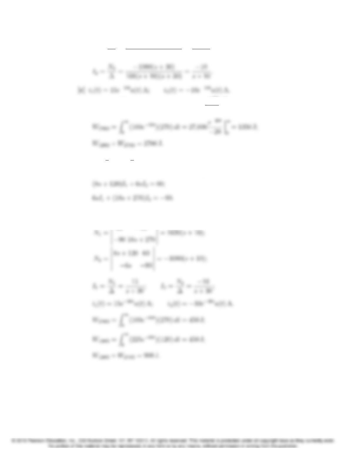
I1=N1
∆=1620(s+ 30)
108(s+ 10)(s+ 30) =15
s+10;
[d] W120Ω=Z1
0
(225e20t)(120) dt = 27,000e20t
20
1
0
= 1350 J;
[e] W=1
2L1i2
1+1
2L2i2
2Mi1i2= 900 + 900 900 = 900 J.
With the dot reversed the s-domain equations are
As before, ∆= 108(s+ 10)(s+ 30). Now,
60 6s
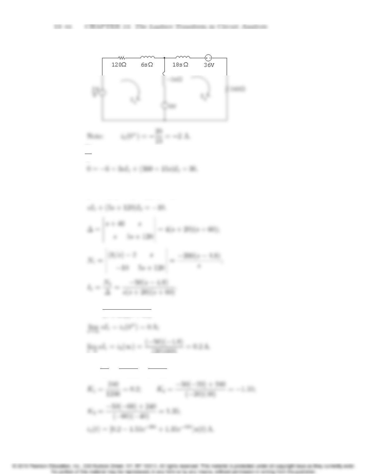
P 13.41 [a] s-domain equivalent circuit is
[b] 24
s= (120 + 3s)I1+3sI2+6
In standard form,
(s+ 40)I1+sI2= (8/s)2;
[c] sI1=50(s4.8)
(s+ 20)(s+ 60);
(20)(60) =0.2A.
[d] I1=K1
s+K2
s+20+K3
s+60.
Problems 13–45
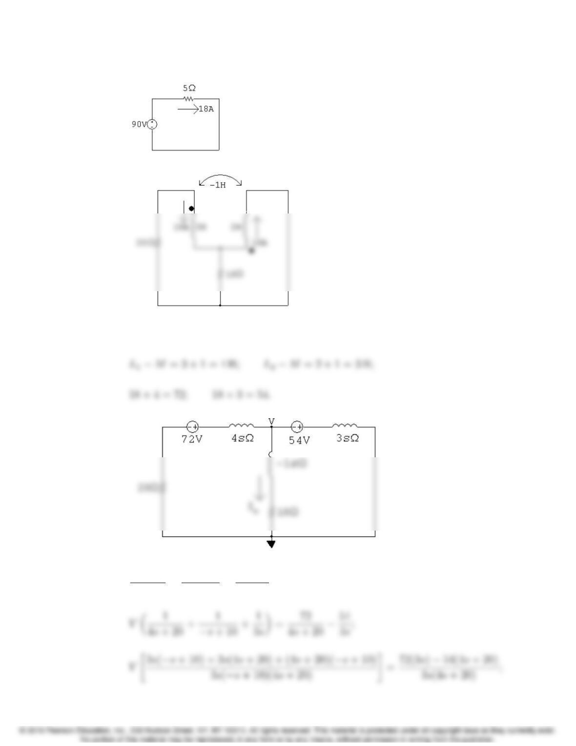
P 13.42 For t<0:
For t>0+:
Note that because of the dot locations on the coils, the sign of the mutual
inductance is negative! (See Example C.1 in Appendix C.)
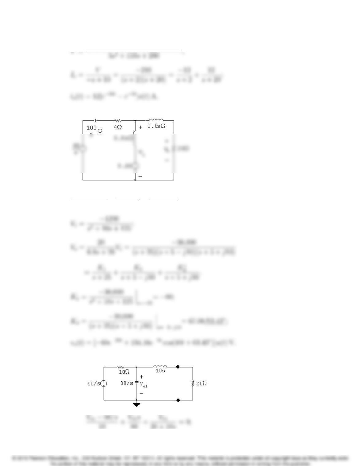
V72
4s+20+V
s+10+V+54
3s= 0;
13–46 CHAPTER 13. The Laplace Transform in Circuit Analysis
P 13.43 The s-domain equivalent circuit is
V148/s
4 + (100/s)+V1+9.6
0.8s+V1
0.8s+20 = 0;
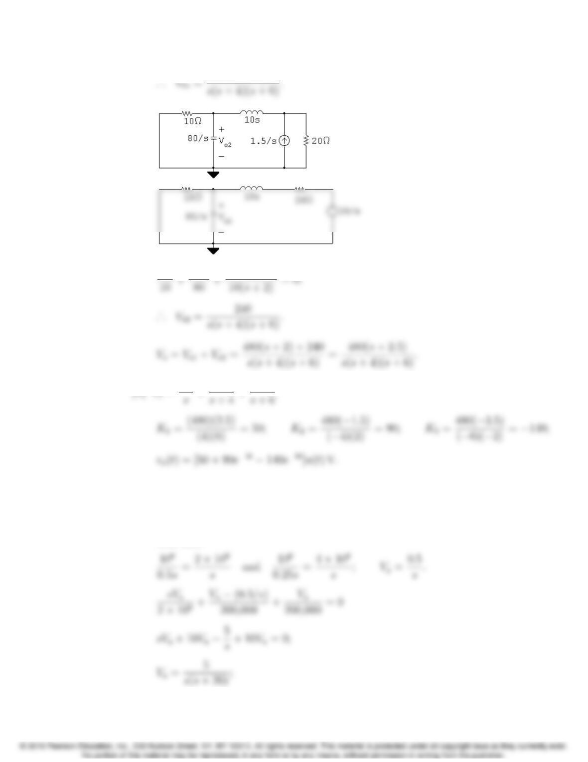
P 13.44 [a] Voltage source acting alone:
Problems 13–47
Vo2
[b] Vo=K1
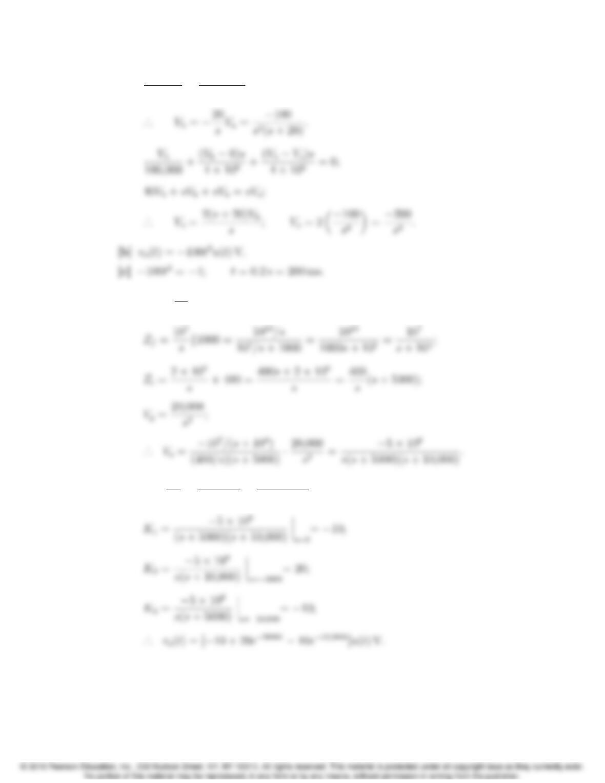
P 13.45 [a] Let vabe the voltage across the 500 nF capacitor, positive at the upper
terminal.
Let vbbe the voltage across the 100 kΩresistor, positive at the upper
terminal.
Also note
13–48 CHAPTER 13. The Laplace Transform in Circuit Analysis
0Va
200,000 +(0 Vb)s
4⇥106=0.
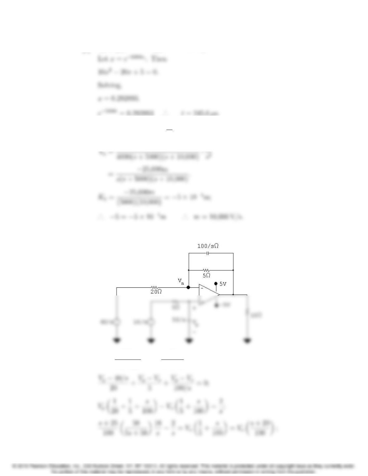
P 13.46 [a] Vo=Zf
Zi
Vg;
[b] Vo=K1
s+K2
s+ 5000 +K3
s+10,000.
Problems 13–49
[c] 10 + 20e5000ts10e10,000ts=5.
[d] vg=mtu(t); Vg=m
s2;
P 13.47 [a]
Vp=50/s
5+50/sVg2=50
5s+50Vg2;
13–50 CHAPTER 13. The Laplace Transform in Circuit Analysis
Vo=100
s+20“16(s+ 25)
10(s+ 10)(s)2
s#=40s+ 2000
s(s+ 10)(s+ 20)
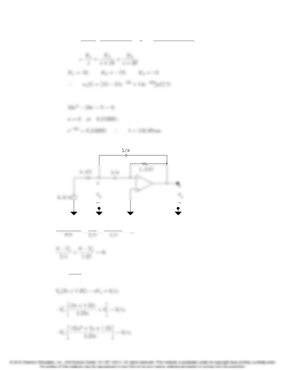
[b] 10 24x+14x2= 5;
P 13.48
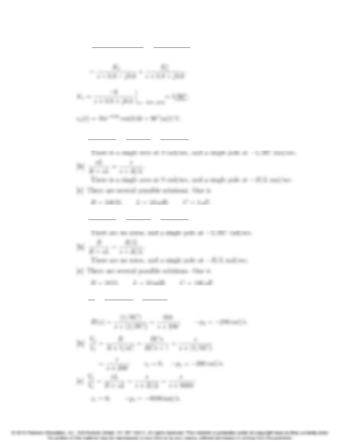
Va4.8/s
Va=Vo
1.25s;
Problems 13–51
Vo=7.5
1.25s2+2s+1.25 =6
s2+1.6s+1
P 13.49 [a] R
R+1/sC =RsC
RsC +1 =s
s+1/RC .
P 13.50 [a] 1/sC
R+1/sC =1
RsC +1 =1/RC
s+1/RC .
P 13.51 [a] Vo
Vi
=1/sC
R+1/sC =1
RCs +1;
13–52 CHAPTER 13. The Laplace Transform in Circuit Analysis
[e]
Vos
4⇥106+Vo
10,000 +VoVi
40,000 = 0;
P 13.52 [a] R
1/sC +sL +R=(R/L)s
s2+(R/L)s+1/LC .
There is a single zero at 0 rad/sec, and two poles:
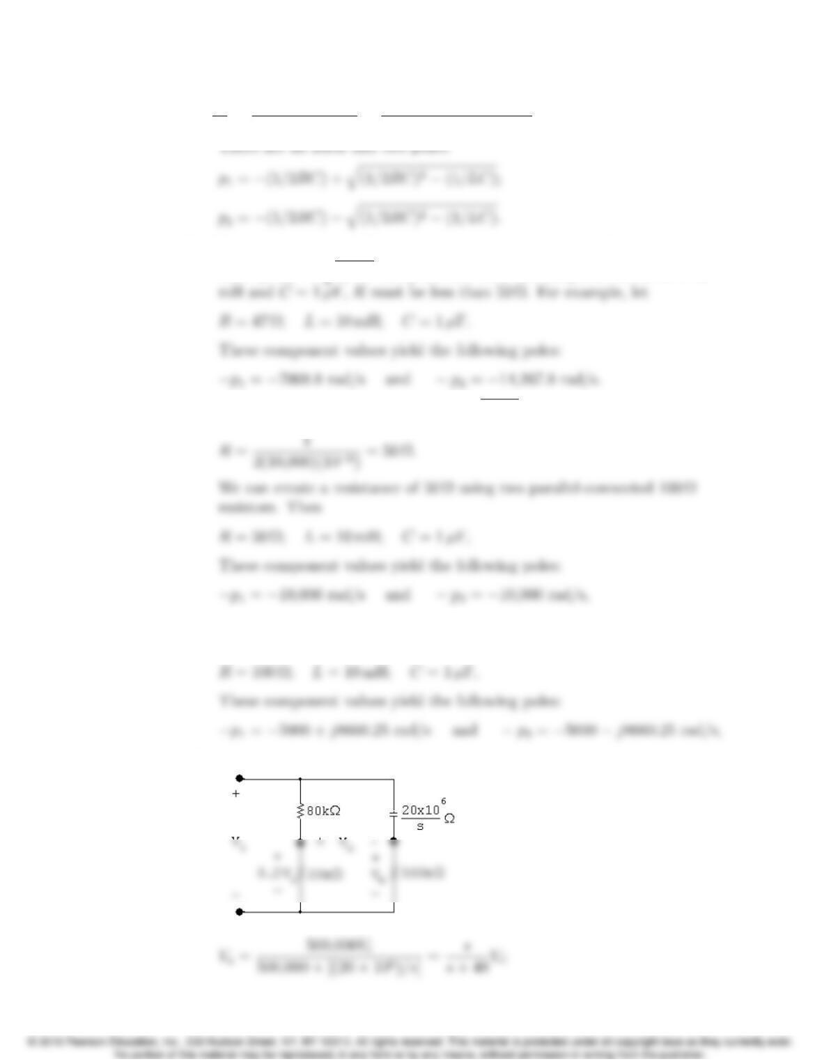
[b] There are several possible solutions. One is
[c] There are several possible solutions. One is
[d] There are several possible solutions. One is
Problems 13–53
P 13.53 [a] Vo
Vi
=Rk1/sC
(Rk1/sC)+sL =1/LC
s2+ (1/RC)s+1/LC .
[b] There are several possible solutions. Any selection of R,L, and Csuch
that 1/2RC < q1/LC will yield two real, distinct poles. When L= 10
[c] To get repeated real poles, 1/2RC =q1/LC, so choose
[d] There are several possible solutions. Any resistor with a value greater
than 50 Ωwill yield two complex conjugate poles. For example, let
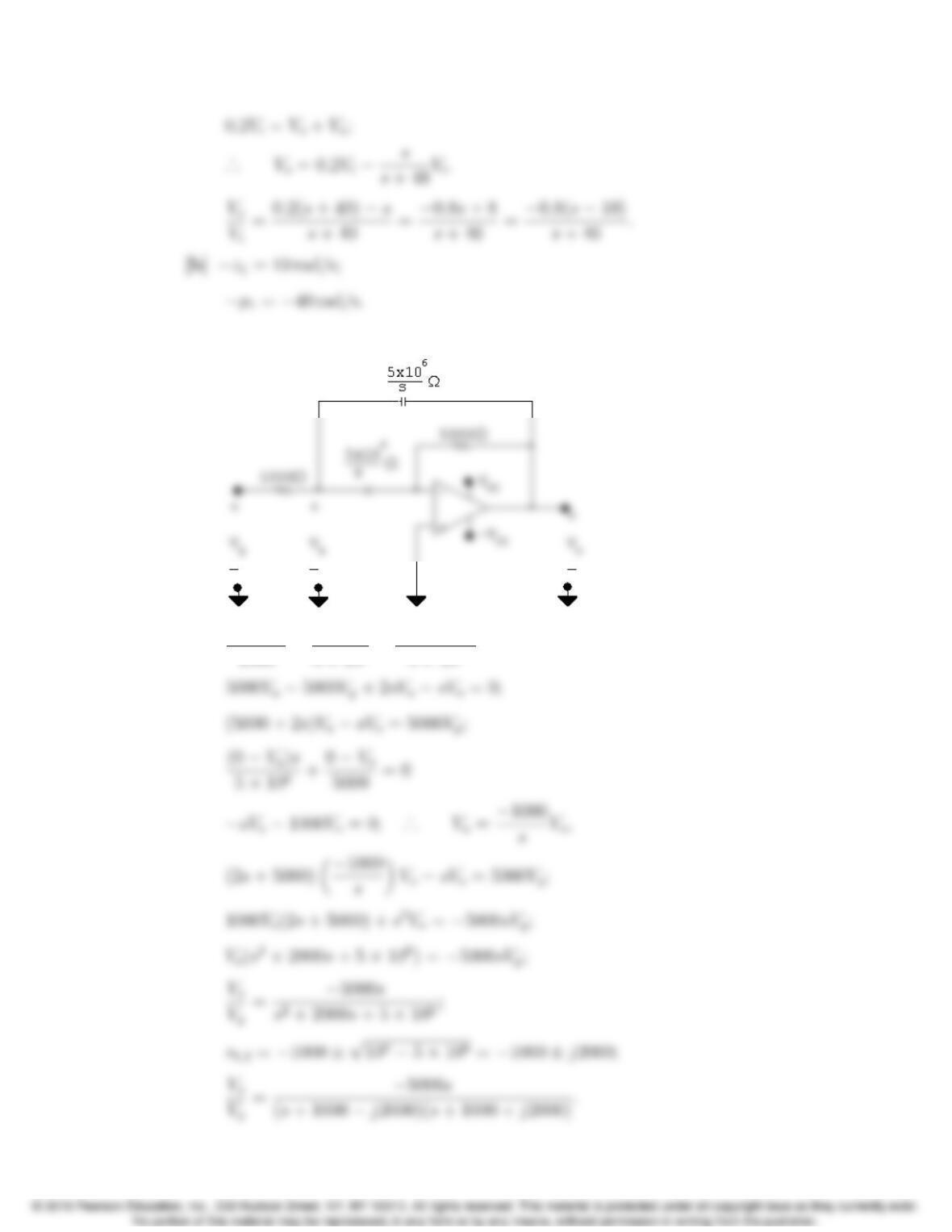
P 13.54 [a]
13–54 CHAPTER 13. The Laplace Transform in Circuit Analysis
P 13.55 [a]
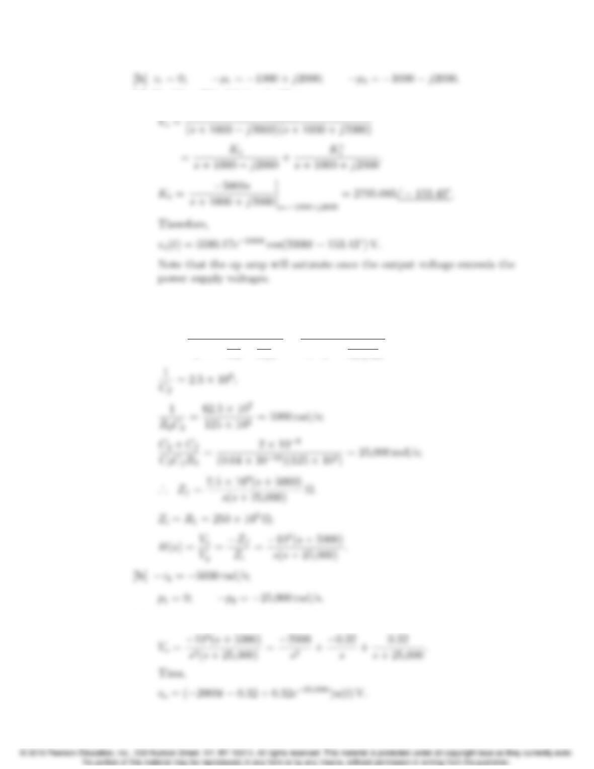
VaVg
Problems 13–55
[c] If vi(t)=δ(t), Vi(s) = 1. Then,
P 13.56 [a] Let R1= 250 kΩ;R2= 125 kΩ;C2=1.6 nF; and Cf=0.4 nF.
Then
Zf=(R2+1/sC2)1/sCf
⇣R2+1
sC2+1
sCf⌘=(s+1/R2C2)
Cfs⇣s+C2+Cf
C2CfR2⌘.
[c] If vg(t)=u(t) then Vg(s)=1/s. Then,
13–56 CHAPTER 13. The Laplace Transform in Circuit Analysis
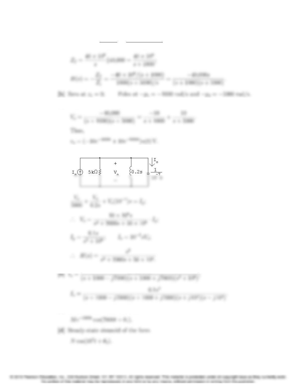
P 13.57 [a] Zi= 1000 + 5⇥106
s=1000(s+ 5000)
s;
[c] If vg(t)=u(t) then Vg(s)=1/s. Then,
P 13.58 [a]
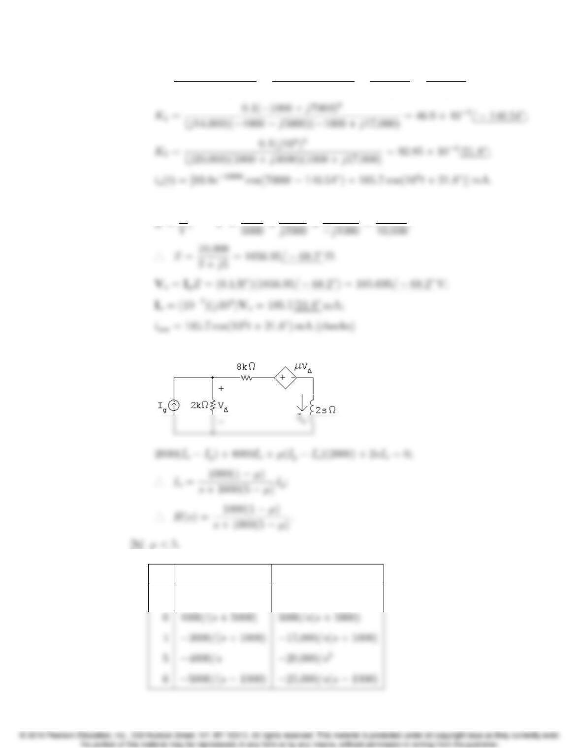
[c] Damped sinusoid of the form
Problems 13–57
[e] Io=K1
s+ 1000 j7000 +K⇤
1
s+ 1000 + j7000 +K2
sj104+K⇤
2
s+j104.
Test:
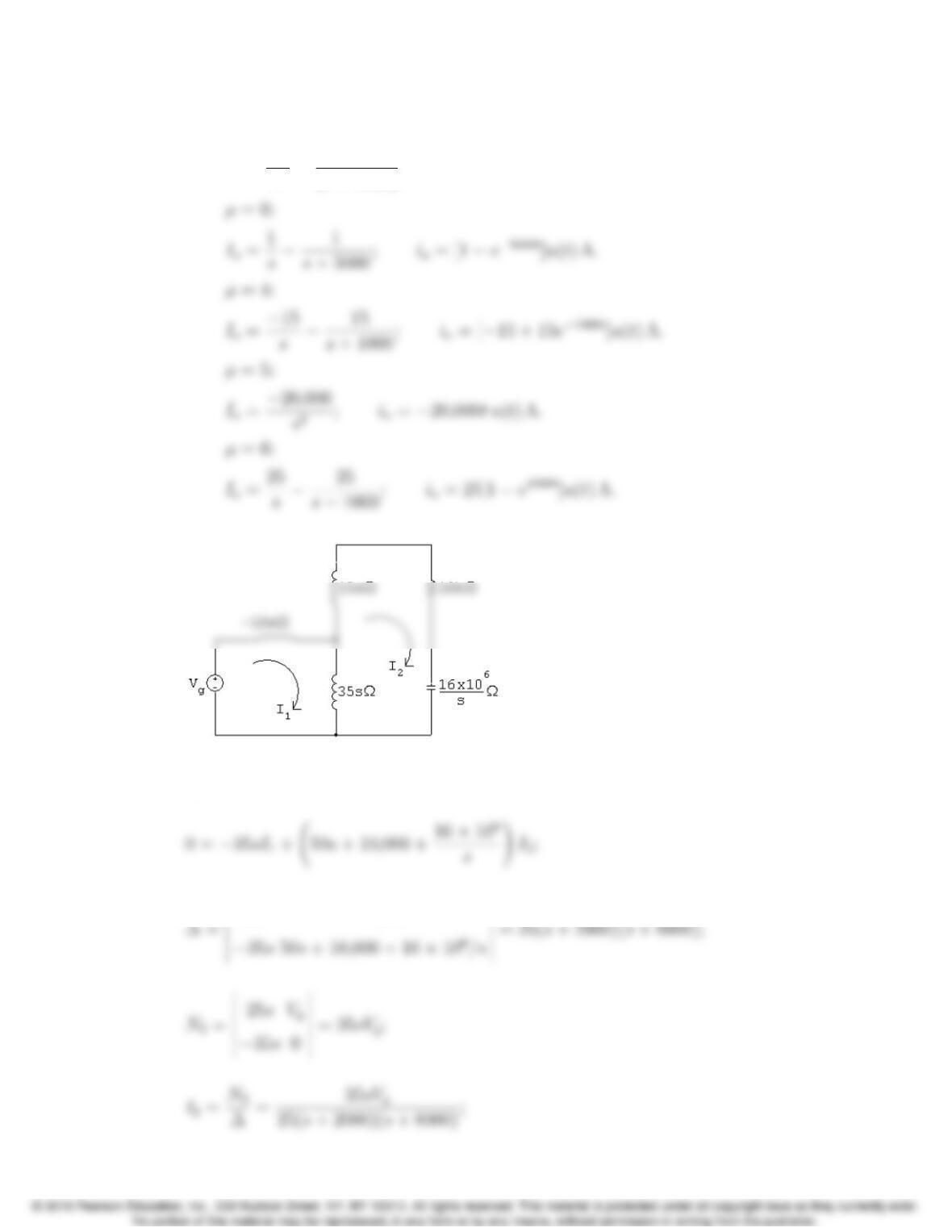
P 13.59 [a]
[c]
µ H(s)Io
3 4000/(s+ 8000) 20,000/s(s+ 8000)
13–58 CHAPTER 13. The Laplace Transform in Circuit Analysis
µ=3:
Io=2.5
s2.5
(s+ 8000);io= [2.52.5e8000t]u(t)A.
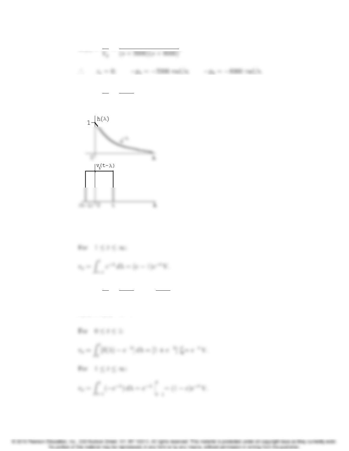
P 13.60
Vg= 25sI135sI2;
25s35s
Problems 13–59
H(s)= I2
=1.4s
P 13.61 H(s)=Vo
Vi
=1
s+1;h(t)=et.
For 0 t1:
vo=Zt
0
eλdλ= (1 et)V.
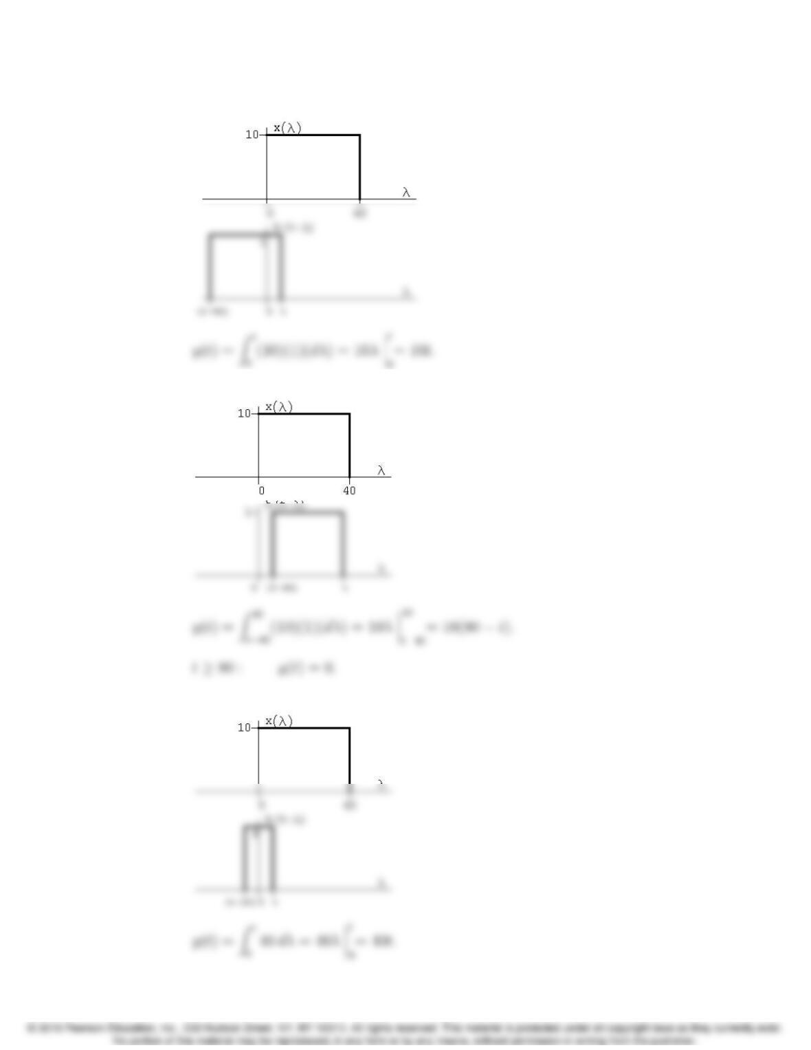
P 13.62 H(s)=Vo
Vi
=s
s+1 =11
s+1;h(t)=δ(t)et;
h(λ)=δ(λ)eλ.
13–60 CHAPTER 13. The Laplace Transform in Circuit Analysis
P 13.63 [a] 0t40:
40 t80:
[b] 0t10: