CHAPTER 13
Exercises
E13.1 The emitter current is given by the Shockley equation:
1exp
T
BE
ESEV
v
Ii
E13.2
α
α
β
1
α
β
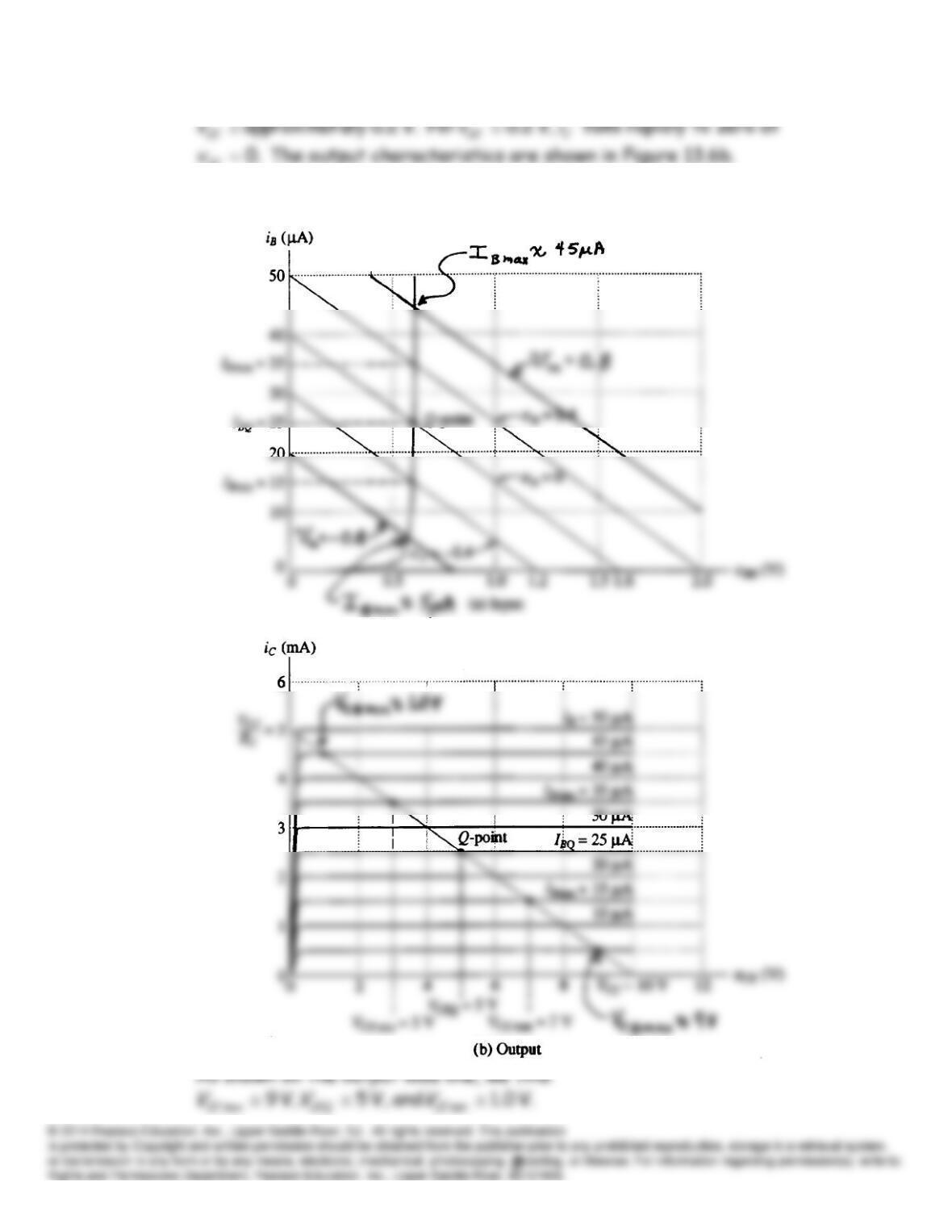
E13.4 The base current is given by Equation 13.8:
which can be plotted to obtain the input characteristic shown in Figure
CE
E13.5 The load lines for
V 0.8– andV 8.0
in
v
are shown:
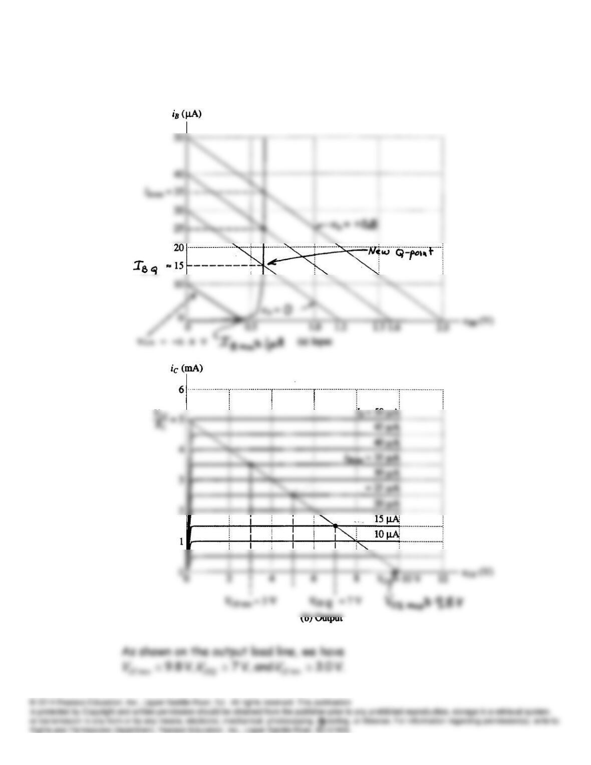
E13.6 The load lines for the new values are shown:
E13.7 Refer to the characteristics shown in Figure 13.7 in the book. Select a
E13.8 (a) Writing a KVL equation around the input loop we have the equation for
Then we write a KCL equation for the output circuit:
The resulting load line is:
From these load lines we find
(b) Inspecting the load lines, we see that the maximum of
v
in corresponds
E13.9 (a) Cutoff because we have
V 5.4 andV 5.0
BC
which is
CE
BVI
E13.10 (a) In this case (
)50β
the BJT operates in the active region. Thus the
equivalent circuit is shown in Figure 13.18d. We have
(b) In this case (
)250β
,the BJT operates in the saturation region.
E13.11 For the operating point to be in the middle of the load line, we want
V 102/
CC
CE VV
and
mA 2
CE
CC
CR
VV
I
. Then we have
E13.12 Notice that a
pnp
BJT appears in this circuit.
(a) For
,50β
it turns out that the BJT operates in the active region.
(b) For
,250β
it turns out that the BJT operates in the saturation
region.
2
R
BE
B
VV
β
B
I
(A)
C
I
(mA)
CE
V
(V)
For the larger values of
21 and
RR
used in this Exercise, the ratio of the
21 and
RR
E13.14
k 333.3
1
RB
V 5
2
R
VV CC
Ω 7.666
1
R
7.108
β
R
AL
E13.15 First, we determine the bias point:
Now we can compute
r
and the ac performance.
Problems
P13.1 To forward bias a
pn
junction, the
p
-side of the junction should be
P13.2 The emitter current is given by:
P13.3 For a BJT, the parameters are defined as:
C
i
α
P13.5 The sketch should resemble Figure 13.1a in the book. In normal
P13.6*
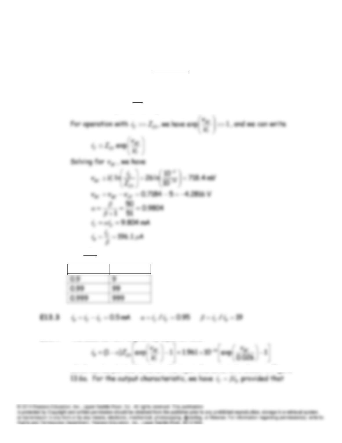
P13.7* The emitter current is given by the Shockley equation:
For operation with
1exp have we ,
BE
ESEV
v
Ii
, and we can write:
β
P13.8
mA 5.0
C
E
Biii
P13.9 From Equation 13.9, we have
P13.11 We have
1exp
T
BE
ESEV
v
Ii
Solving for the saturation current:
For
mA 1
E
i
, we have
P13.12 Solving the Shockley equation, we have
At 310 K, we have
P13.13 From the circuit, we can write:
P13.14* We have:
BE
v
Adding the respective sides of these equations, we have:
P13.15 Writing a current equation at the collector of
1
Q
, we have:
P13.16 We have
11211
1
211
21 )1(
BB
E
B
CCCeq iiiiiii
. Then we can write
P13.17 The Shockley equation states:
Thus,
ESEIi
to alproportion is
, and we can write:
1
Q
mA 110 111
BBB iii
β
As in the solution to Problem 13.11, we have
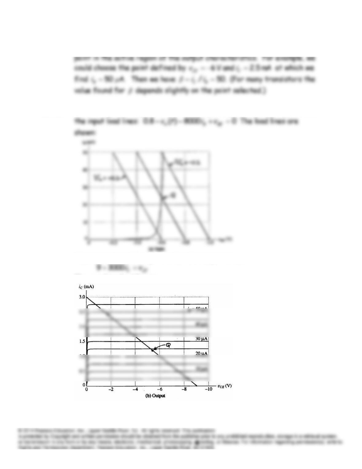
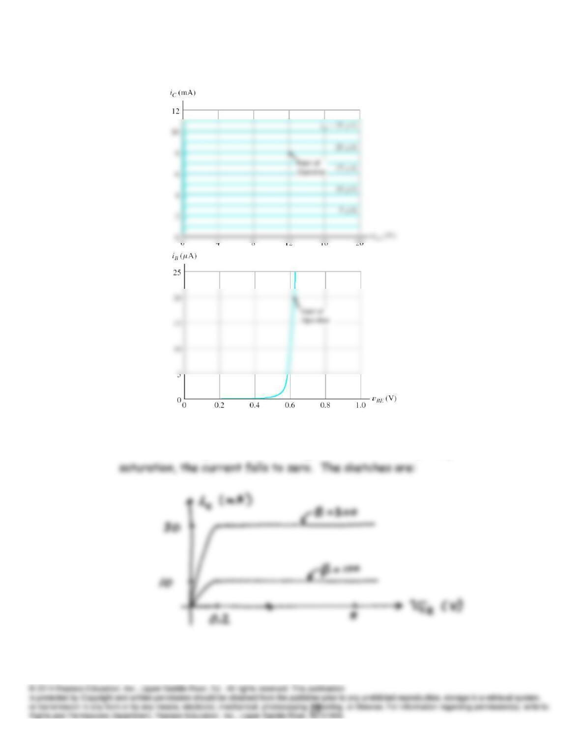
P13.18* We select a point on the output characteristics in the active region and
P13.19* At
mA 1.0 and 180
B
iC
, the base-to-emitter voltage is approximately:
P13.20
P13.21 In the active region (which is for
V 2.0
CE
v
), we have
B
Cii
β
. In

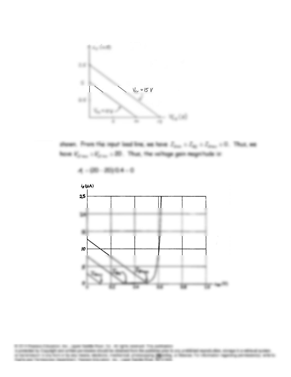
P13.22* Following the approach of Example 13.2, we construct the load lines
P13.23 Distortion occurs in BJT amplifiers because the input characteristic of
P13.24 The slope of the load line does not change as
VCC
changes.
P13.25 Following the approach of Example 13.2, we construct the load lines
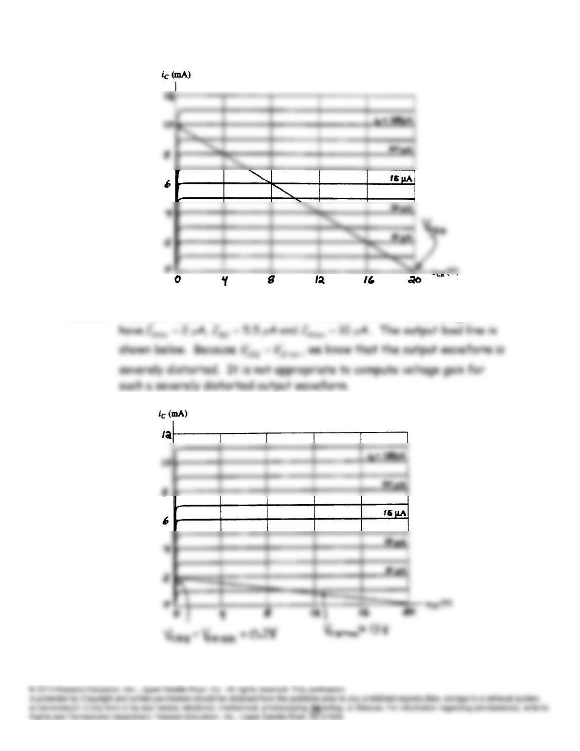
P13.26 The input load line is the same as in Problem P13.22. Thus, we again
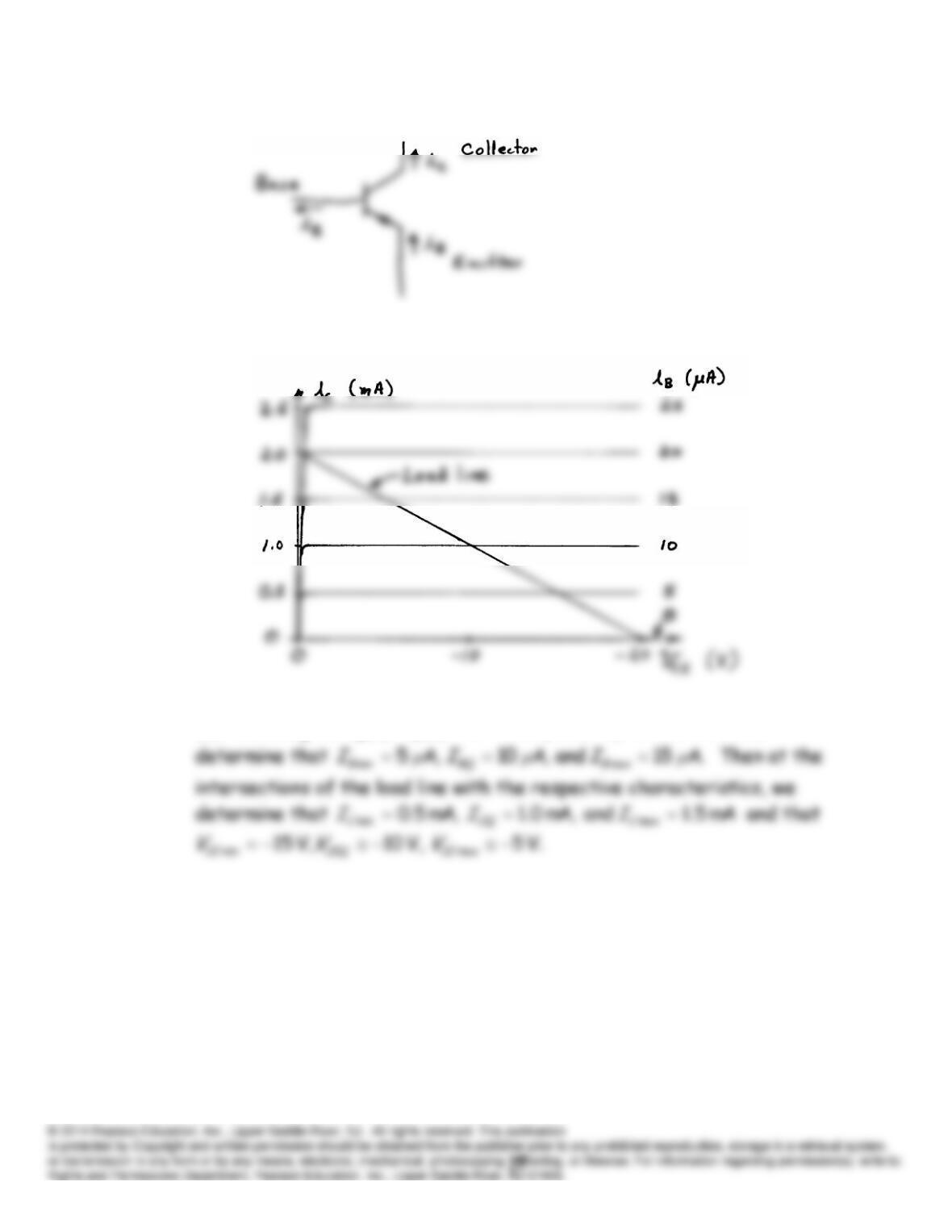
P13.27
P13.28* (a) and (b) The characteristics and the load line are:
(c) We are given
)2000sin(510)()(
ttiti s
B
. From which we
(d) The sketches of
vCE
(
t
) are: